



















This video demonstrates how to control a pneumatic cylinder using an Arduino microcontroller by interfacing it with a 5/2 solenoid valve through a MOSFET transistor, where applying 12V to the valve's solenoid causes the cylinder rod to extend while no voltage causes it to retract, enabling programmable linear motion control.
Control Pneumatic Cylinder with Arduino: MOSFET Circuit Design
Added:Basic Arduino programming, including writing sketches and configuring digital I/O pins.
Fundamental electronic principles, specifically how N-channel MOSFETs function as voltage-controlled switches for high-current loads.
Basic pneumatics concepts, including the mechanical operation of double-acting cylinders and the routing of air in a 5/2-way solenoid valve.
The behavior of inductive loads (solenoids) and the necessity of using flyback diodes to prevent voltage spike damage.
Implementing sensor feedback (such as magnetic reed switches or limit switches) for closed-loop pneumatic control.
Developing complex, multi-cylinder sequences using Finite State Machines (FSM) in Arduino.
Transitioning from Arduino prototypes to industrial-grade PLC (Programmable Logic Controller) hardware and standard 24V control circuits.
Exploring proportional pneumatic systems to control cylinder speed, pressure, and positioning rather than binary (fully extended/retracted) states.
261.4K views5.1Klikes4:36Original Release: 2019-12-29
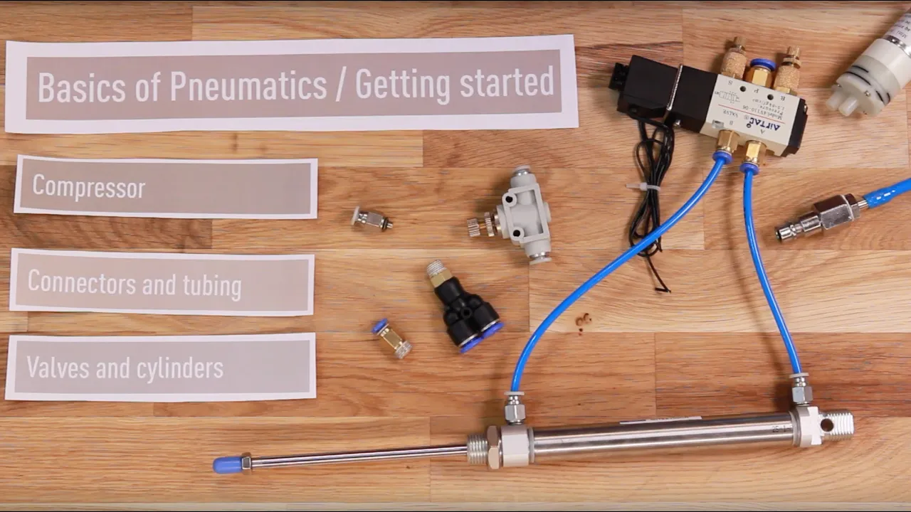
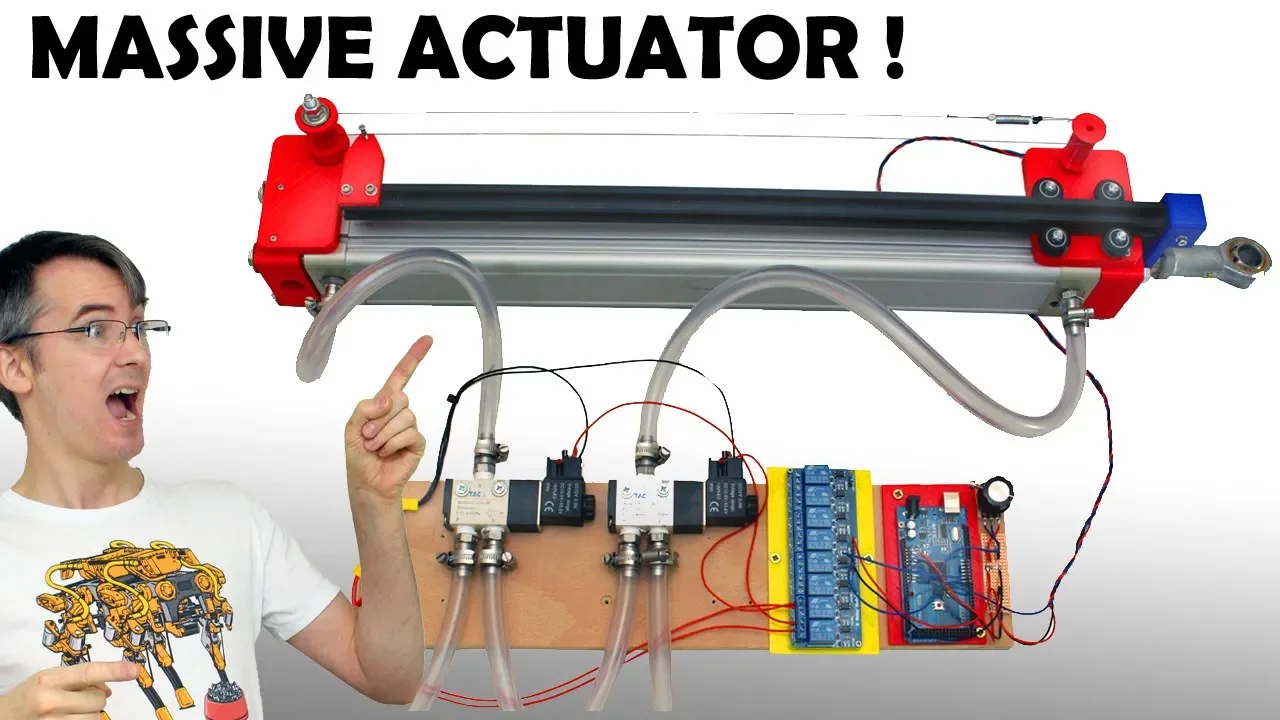
hey what's up it's triggy and today we'll be controlling a pneumatic cylinder with an Arduino the whole point of robots is that they move the most typical source of movement comes from motors which convert electrical energy to rotational motion sometimes we want to move linearly though instead of spinning a common solution is to use a linear actuator which by the way is actually just a motor spinning an ACME rod and like motors linear actuators can be made very precise and can be powered electrically the trouble is they're not all that powerful and even not really that fast and not really that forceful you can trade-off force for speed and vice versa but you're still very much limited by the overall power output so for cases where you need speed and power and not so much fine precision control consider pneumatic cylinders for your project a quick refresher on pneumatic cylinders here's a cross-section of a cylinder when air is applied to the left input the cylinder rod is forced to extend when air is applied to the right input the rod is forced to retract we can control the flow of air into the cylinder with a five two control valve it takes a single stream of air as an input and controls the air flow through the two outputs it also has to exhaust outputs to control the flow speed the air out of the cylinder and thereby the speed of the rod here we'll add some teflon tape to quick connect fittings a fun fact about building stuff in the u.s. is that not only do you have to be comfortable with both metric and imperial units you also need to buy WAC parts to convert between them for example the threads here a quarter twenty two match the air compressor while the input for the tube is six millimeter to match the cylinder now that we have all the connectors and exhaust attached we can look into how the air flow is controlled the electrical terminals are tucked away in here so we can unscrew the sections to access them when we apply 12 volts to the terminals a solenoid activates and air flows through one of the two outputs let's call it output one this makes a cylinder rod extend when no voltage is applied the solenoid is not active and air flows through output too and the rod retract so all we have to do is apply and not apply 12 volts to the valve to control the cylinder here we can hear the solenoid clicking when I attach and detach the battery let's cut some six millimeter tubing to connect our input to the control valve and the valve outputs to the cylinder inputs [Music] now we can power up our air compressor and connect it to our system we haven't worked out any of the electrical stuff yet but the control valve has a test button which we can use instead of the solenoid to activate a cylinder it looks like everything's working so far but we don't wanna have to press this button constantly we want to control the cylinder with a micro controller like an Arduino to do that we'll use a transistor this one is an fqp 30 n zero 6l MOSFET this will act as a switch that we can control with a 5 volt signal if we apply 5 volts to the gate pin of the MOSFET we allow current to flow will power one side of the breadboard to 5 volts with your dueños 5 volt and ground pins will then attach cables to the other half of the breadboard which will later connect to a 12-volt power source we'll also tie the grounds together will then connect a signal wire between the gate of the MOSFET and one of the digital output pins of the Arduino let's say pin 5 will add a pulldown resistor to the gate then add indicator LEDs to the 12-volt source the 5 volt source and the gate the Salafist keep track of what our circuit is doing in action will then connect output cables between the 12 volt rail and the MOSFET drain pin this is the output and will connect to the control valve solenoid and that's it the 12 volt indicator LED turns on when we connect to all volts and likewise a 5 volt indicator LED turns on when we connect 5 volts let's write a super simple script to control the behavior of the cylinder we'll assign our signal pin to be pin 5 declared as an output pin and then alternate between setting the pin high and low with a one-second pause in between let's connect the battery via Arduino and the solenoid to the circuit if we touch the signal pin to the 5 volt rail we see the blue LED turns on in the solenoid activates if we connect the signal wire to our output pin the LED and solenoid activate at a steady rhythm let's attach the cylinder connect the pressurised air and connect the signal pin to our output pin we see our cylinder extends and retracts exactly as we specified in the code [Music] and now we have successfully controlled behavior of a pneumatic piston with an Arduino button that's it for this video thanks for watching if you enjoy this kind of content be sure to subscribe and I hope you like the video
Up Next
20:32
Brushed DC Motor Drivers: Theory, PWM, and H-Bridge Design
@ElectroBOOM
4M views•2019-01-25

30:32
Ultrasonic Transducers: Resonant Frequency Measurement and Horn Design
@imajeenyus42
229.9K views•2017-02-22

54:16
Polymer Environmental Degradation: Mechanisms & Stabilization
@iit
1.8K views•2012-07-10

33:39
How a Student's Question Saved a NYC Skyscraper from Collapse
@veritasium
22.8M views•2025-04-26
Related Study Plans & Knowledge Roadmaps
Structured learning paths in Engineering
engineering
Building Acoustic Levitators: Physics & Arduino
01The Physics of Sound and Standing Waves
02Piezoelectric Transducers and H-Bridge Drivers
03Arduino Programming: Generating 40 kHz Signals
+ 2 more learning modules
14h5 modules
Explore Roadmap
engineering
Building Peltier Cloud Chambers: Particle Tracks
01Cosmic Rays & Cloud Chamber Physics
02Thermoelectric Cooling (TEC) Fundamentals
03Custom Liquid-Cooling Loop Design
+ 2 more learning modules
18h5 modules
Explore Roadmap
engineering
Yagi-Uda Antennas: Modeling, Build & VNA Test
01Introduction to RF and Antenna Fundamentals
02Yagi-Uda Antenna Design Principles
03Antenna Modeling and Simulation in 4NEC2
+ 2 more learning modules
18h5 modules
Explore Roadmap
engineering
ECG Monitor Design: Op-Amps, Filters & Noise
01Electronics & Breadboard Basics
02Op-Amps and Instrumentation Amplifiers
03Bioelectricity and ECG Fundamentals
+ 2 more learning modules
18h5 modules
Explore Roadmap