A 3D printed anti-vibration mount for drones can be constructed using a combination of 3D printed components and cable ties to secure TPU printed sections, effectively reducing vibration transmission during flight and improving footage stability.
Soft-Mount Anti-Vibration Drone Test with Reelsteady GO
Added:Deep Dive
Understanding of drone propulsion dynamics, specifically how brushless motors and unbalanced propellers generate high-frequency mechanical vibrations.

Mavic Air 2 Propellers by Master Airscrew - They Need to Fix This.
32.4K
Unbalanced propellers cause significant vibration in drones. The Master Airscrew propellers for the Mavic Air 2 exhibited noticeable shaking and vibration during flight, which was not observed with stock DJI propellers. This vibration can indicate improper blade cutting, manufacturing defects, or imbalance issues.
Click to watch →
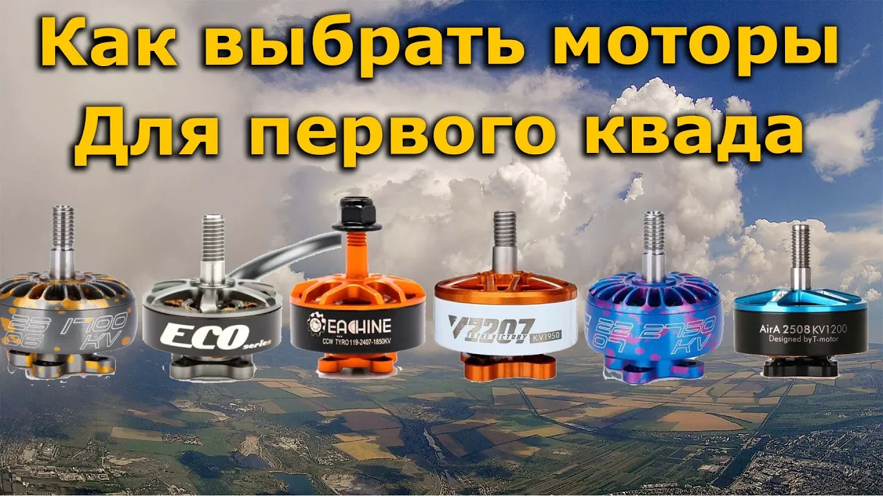
Как выбрать моторы новичку для первого ФПВ квадрокоптера!? DYS EMAX T-MOTOR Racerstar
82.3K
KV rating indicates RPM per volt, directly affecting propeller selection. Higher KV motors require smaller propellers: 2,400 RPM per volt suits 5-inch props, while 1,200-1,300 RPM per volt suits 7-inch props. Propeller markings (e.g., 5040) indicate diameter and pitch—the distance the prop advances per rotation. Higher pitch propellers require more power. Motors with higher RPM per volt create more vibration frequencies that flight controllers must filter, making them less smooth and harder to configure. Motors with 2,400 RPM per volt are easier to configure than those with 2,700 RPM per volt because they operate in narrower, more manageable vibration ranges.
Click to watch →

Emax Mt 3110-480 Kv Тест Rc моторов, Rc motor testing
1.1K
Brushless motors generate electromagnetic impulses that create vibrations, which can be tested using a simple setup with a laser pointer, mirror, and ruler to detect imbalance; these vibrations can damage electronic equipment like accelerometers and should be mitigated through proper damping materials (such as foam or porolon) and secure fastening with thread lockers to prevent loosening.
Click to watch →

MECÁNICA RACIONAL - ANEXO 20: Transmisibilidad (Clase Virtual)
1.4K
This section presents a practical example of unbalanced motor vibration analysis. A 25 kg motor is supported by four springs (200 N/cm each) with a 30g unbalanced mass at 15 cm from the axis. The motor operates at 1500 rpm. The solution involves: (1) finding the equivalent spring constant (800 N/cm), (2) calculating the natural frequency, (3) finding the forcing frequency, (4) applying the transmissibility formula to find the amplitude. The example demonstrates how to apply the theoretical concepts to a real-world engineering problem.
Click to watch →
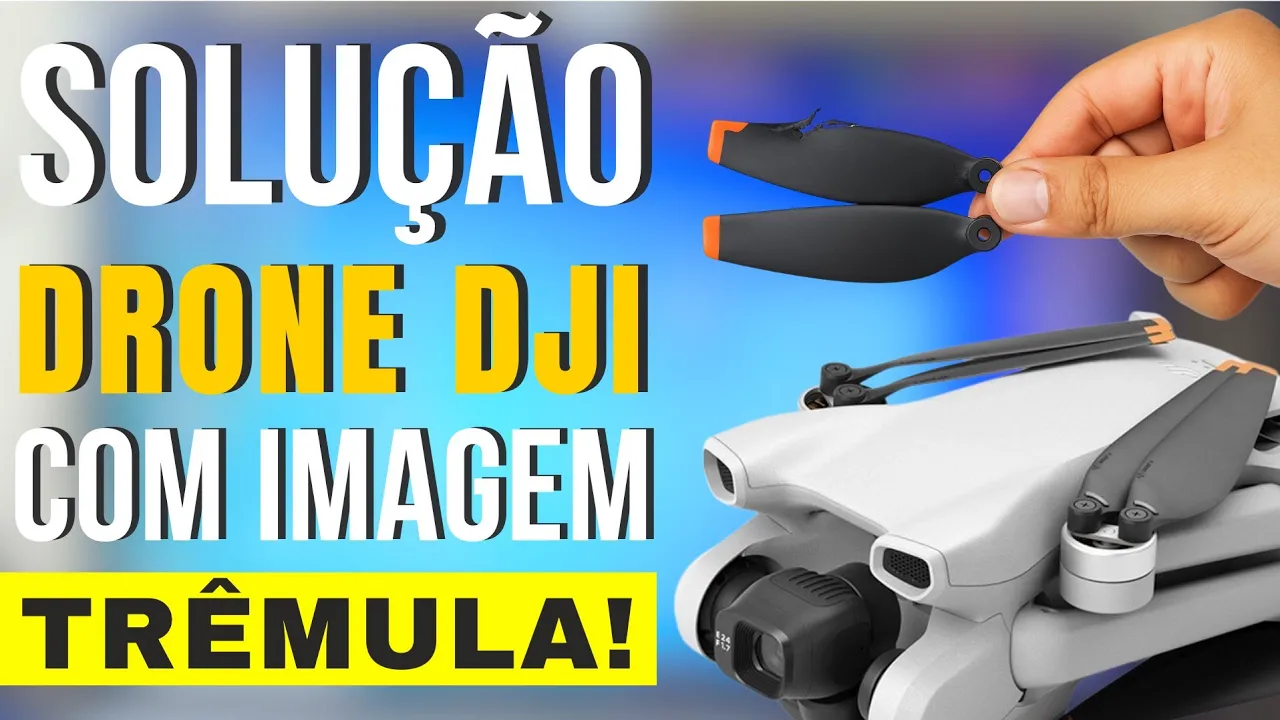
Drone DJI Mini 3 IMAGEM TRÊMULA e VIBRANDO ao VOAR! | O defeito era algo INIMAGINÁVEL e eu RESOLVI!🥇
2.3K
Damaged or mismatched propellers are a common cause of drone vibration. Even new propellers from the original kit can cause issues if the pairs are mismatched. To diagnose, swap propeller positions between motors—if vibration moves to the opposite motor, the original pair was defective. Test by holding the drone firmly in your hand during flight; a vibrating motor will tremble at a frequency that can hurt your fingers, while a functioning motor feels smooth and fluid. Visual confirmation at high frame rates (60+ fps) can also reveal vibration patterns.
Click to watch →
Deep Dive
Basic knowledge of IMUs (Inertial Measurement Units), particularly how gyroscopes record angular velocity and how physical vibrations introduce noise into this sensor data.

Intro to Inertial Measurement Units (IMU)
46.1K
An Inertial Measurement Unit (IMU) is a sensor system that measures orientation and motion using gyroscopes (which detect angular rotation rates but suffer from bias and drift requiring correction algorithms like Kalman filters) and accelerometers (which measure linear acceleration including gravity to determine tilt angles but require filtering to reduce noise); IMUs are classified by their sensor accuracy, with hobbyist-grade units having biases around 0.01g and 100°/hour, while high-end aerospace IMUs achieve biases below 0.00001g and 0.1°/day, and sensor fusion techniques combine multiple sensor readings to improve overall measurement accuracy.
Click to watch →

Basic Knowledge Introduction of Service Robots
863
IMU (Inertial Measurement Unit) is a sensor mainly used to detect and measure acceleration and rotational motion, realized through the law of inertia. These sensors range from small MEMS sensors to laser gyroscopes with very high measurement accuracy. The most basic inertial sensors consist of three accelerometers and three gyroscopes. Gyroscopes detect angular velocities in three directions, while accelerometers detect accelerations in three directions. Position information relative to the starting point is obtained by integrating the signals of the accelerometer and gyroscope. Since IMU is not affected by wind and other environmental conditions, its independence makes it one of the key technologies in automatic driving.
Click to watch →

Конференция «Я Железо 2024». SoftWare track
3.4K
IMU combines gyroscope, accelerometer, and magnetometer to measure motion: (1) Gyroscope measures angular velocity; (2) Accelerometer measures linear acceleration; (3) Magnetometer measures magnetic field direction (compass). Theoretically sufficient for position and orientation estimation, but practical challenges include: (1) Sensor noise; (2) Vibrations causing measurement errors; (3) Integration drift over time. Requires filtering to extract useful information.
Click to watch →

ROB 311 Fall 2022: Digital communications
336
IMUs (Inertial Measurement Units) measure physical processes and convert them to digital values. They are described by degrees of freedom and axes. Basic IMUs measure linear acceleration and angular velocity, while some versions include magnetometers. Internally, IMUs use MEMS structures that vibrate to measure acceleration, with natural frequencies around 500 Hz. Key error types include bias error (inherent sensor error), mounting misalignment error (from incorrect installation), and random walk errors (from Gaussian noise that accumulates when integrated over time). IMUs like the MPU-6050 use complementary or Kalman filters to fuse acceleration and angular velocity data, with communication abstracted for students.
Click to watch →

How robots navigate the world: Sensors, Mapping & Localization – A Talk by Naveen Arulselvan
1.1K
Inertial Measurement Units (IMUs) contain accelerometers and gyroscopes that measure linear acceleration and angular velocity respectively. Accelerometers detect forces acting on a suspended mass, allowing calculation of linear acceleration by resolving forces perpendicular to gravity. Gyroscopes measure rotational rates. Both sensors have significant noise: accelerometers produce high-frequency noise, while gyroscopes drift slowly over time. These complementary characteristics lead to complementary filter techniques that combine both sensor types for improved orientation estimation.
Click to watch →
Deep Dive
Familiarity with 3D printing filaments, specifically the mechanical differences between rigid plastics (like PLA) and flexible elastomers (like TPU) used for shock absorption.
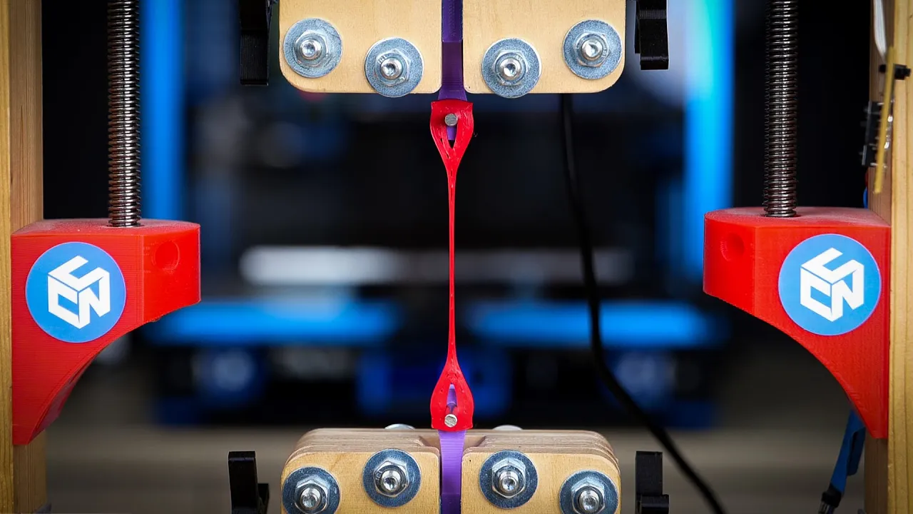
Why aren't more people 3D Printing this Indestructable Filament?
655K
Flexible TPU materials demonstrate fundamentally different mechanical behavior compared to rigid filaments. FiberFlex 40D shows yield strength of ~7 MPa versus PLA's 60 MPa, with excellent flexibility and yielding before failure. Fiber-reinforced variants dramatically increase strength (up to 50+ MPa) but reduce flexibility and create anisotropic behavior dependent on printing orientation. Impact testing reveals exceptional energy absorption, with carbon fiber reinforced TPU completely stopping hammer impacts. Friction testing demonstrates a clear trend: softer materials generate higher friction coefficients, explaining why car tires fall in the same hardness range as optimal friction performance. Bouncability testing of printed spheres revealed that hardness alone doesn't determine springiness—the specific TPE type matters more. Fillamentum PEBA and FiberFlex 30D both lost only 26-27% energy, bouncing back to 58cm and 53cm respectively. Applications depend on hardness: use 60+D for tough parts replacing PLA/PETG, 30-40D for gaskets/hinges, and ultra-soft Filaflex 60A for specialized challenges.
Click to watch →

How to Choose a Filament Type - PLA, ABS, PETG, & TPU Filaments - A Guide To 3D Printing Filament
70.3K
This video explains the four main 3D printing filament types: PLA (polylactic acid) is beginner-friendly with low melting point (215°C nozzle, 55°C bed), affordable, and offers the widest color variety; ABS (acrylonitrile butadiene styrene) provides higher tensile strength and heat resistance but requires higher temperatures (245°C nozzle, 95°C bed) and an enclosed printer to prevent warping; PETG (polyethylene terephthalate glycol) combines PLA's ease of printing with ABS-like strength and minimal warping while producing no odors; and TPU (thermoplastic polyurethane) offers flexibility for items like watch straps and phone cases but requires careful moisture control and direct drive extruders due to its elastic properties.
Click to watch →

I 3D Printed Your Bad Pokemon Video Ideas
243.3K
TPU (Thermoplastic Polyurethane) is a flexible, stretchy filament that can be combined with rigid PLA (Polylactic Acid) in 3D printing. This combination allows for the creation of objects with different mechanical properties in different regions. The Wobbuffet punching bag demonstrates this by using hard PLA for structural components and soft TPU for the flexible body, creating a functional punching bag that can withstand impact.
Click to watch →

All the Different 3d printing Filaments Explained!
214.4K
TPU, TPC, and TPE are thermoplastic elastomers—flexible plastics. They are not the strongest filaments but offer high flexibility due to their wiggly nature. They print best in direct drive setups but can work over bowden tubes at slower speeds. TPU prints well around 210-230°C with a heated bed optional. Printing speeds must be much slower than other polymers to prevent stretchy filament from winding around extruder gears. TPU doesn't shrink or warp much, so no enclosure is needed. Among these, TPU is most common due to higher UV resistance and heat resistance.
Click to watch →

Top 3 Best Filaments for 3D Printing
35.6K
For practical 3D printing, three filaments stand out: PLA for general-purpose projects requiring fast, clean, and reliable printing (ideal for boxes, holders, and components); TPU for flexible applications where rigidity would cause damage, with the unique ability to control flexibility through printing temperature (e.g., Vario Shore TPU transitions from 92A to 55A hardness); and PETCF (carbon fiber reinforced PET) for engineering applications requiring strength to support real loads or body weights, offering durability without the smell issues of other engineering materials.
Click to watch →
Deep Dive
The core concept of gyro-based video stabilization, which requires clean, uncorrupted gyroscope log data synced to video frames to computationally remove camera shake.

Jak zabrać się za stabilizację z Gyroflow? Cinelifter Diatone X8 + Canon RP + Insta360 GO2 YOLO!
11K
Video stabilization requires three components: stabilization software, gyroscope data, and lens profile. GoPro cameras embed gyroscope data directly in video files, enabling automatic loading. The software displays gyroscope data as X, Y, Z axis lines, with the 'Auto Sync' feature analyzing image movement to generate stabilization lines. Creating lens profiles requires recording calibration videos with identical settings to actual footage (same lens, focal length, aperture, resolution). The checkerboard pattern must fill all frame corners at multiple distances. For dual camera setups, both cameras must start and stop simultaneously. Gyroscope data often contains noise requiring low-pass filtering (optimal around 45 Hz). The software may show inverted axes, requiring orientation adjustments by changing axis values from small to large letters.
Click to watch →

GYROFLOW, LE HACK DE LA STABILISATION VIDÉO ! (DINGUERIE)
25.1K
Camera stabilization refers to techniques that reduce unwanted camera movement in video footage. There are three main types: in-body image stabilization (IBIS) where the sensor moves on motors, mechanical stabilization using gimbals or lens systems, and gyroscopic stabilization using internal sensors. Gyroscopes detect camera movement and orientation, allowing software to compensate for shake. This technology is available in modern cameras, smartphones, and drones, and can be applied both during recording and in post-production.
Click to watch →

SONY Catalyst Browse | Это другое!
24.2K
Sony Catalyst Browse is a free post-production software that stabilizes video by analyzing gyroscope data recorded during capture, compensating for camera shake through frame analysis and slight cropping; it works best when shooting at 50 fps with 1/400s shutter speed and should not be combined with in-camera electronic stabilization, as the software requires raw gyroscope data to function effectively.
Click to watch →

Como ESTABILIZAR DE GRAÇA vídeo das câmeras SONY - Gyroflow é vida!
7.2K
Gyroflow is a free video stabilization software that reads gyroscope data embedded in camera files to counteract shake. Unlike paid solutions like Catalyst Browser, it works with Sony, GoPro, and other cameras that record gyroscope information. The software reads movement data in all axes (X, Y, rotation) and counteracts it by rotating the image in the opposite direction. For optimal results, disable in-camera stabilization and record at 60+ FPS with 10-bit color depth. The software can read lens profiles to correct distortion and provides a preview of gyroscope data before processing.
Click to watch →

Digital Video Stabilization and Rolling Shutter Correction using Gyroscopes
7.7K
This segment traces the evolution from traditional feature-based video stabilization to the proposed gyroscope-based approach. Feature-based methods track image features to recover camera motion but suffer from computational expense and brittleness under poor lighting, motion blur, noise, and scene motion. The video demonstrates these limitations through examples showing popping and jittering artifacts. The proposed solution leverages built-in device gyroscopes to directly measure camera orientation, bypassing image analysis entirely. By integrating gyroscope readings and applying low-pass filtering, a stabilized synthetic camera trajectory is reconstructed. This approach provides more reliable motion estimation because it is independent of visual content quality and scene conditions.
Click to watch →
Prerequisite Knowledge
- Concept 01Understanding of drone propulsion dynamics, specifically how brushless motors and unbalanced propellers generate high-frequency mechanical vibrations.
- Concept 02Basic knowledge of IMUs (Inertial Measurement Units), particularly how gyroscopes record angular velocity and how physical vibrations introduce noise into this sensor data.
- Concept 03Familiarity with 3D printing filaments, specifically the mechanical differences between rigid plastics (like PLA) and flexible elastomers (like TPU) used for shock absorption.
- Concept 04The core concept of gyro-based video stabilization, which requires clean, uncorrupted gyroscope log data synced to video frames to computationally remove camera shake.
Subsequent Learning
- Step 01Advanced flight controller signal filtering, including the configuration of RPM filtering and Dynamic Notch Filters in Betaflight to software-filter residual noise.
- Step 02Applied mechanical design for vibration isolation, involving the study of dampening coefficients and calculating resonance frequencies for custom-engineered camera mounts.
- Step 03Comparative analysis of hardware-level physical stabilization (such as mechanical gimbals or wire-rope isolators) versus software-level post-processing.
- Step 04Exploration of open-source stabilization alternatives like Gyroflow, including how to extract, parse, and manually synchronize raw blackbox gyro data with non-native camera systems.
Mount Design
Flight Test
Mount Design
0:00Playing Section
- 1
Showcases a custom anti-vibration mount.
- 2
Uses 3D-printed base and TPU top secured with cable ties.
Rigid Mounting and Digital Filtering vs. Mechanical Soft-Mounting
While soft-mounting is intended to mechanically dampen high-frequency vibrations, a strong counter-argument exists in favor of rigid mounting paired with digital filtering. Critics in the FPV community point out that soft-mounting can introduce unwanted mechanical play, phase delay, and low-frequency resonance. Specifically for post-stabilization software like Reelsteady GO, which relies on precise synchronization between the gyro sensor and the camera, soft-mounting the camera independently from the flight controller can actually degrade stabilization quality. If the camera wiggles on a soft mount while the gyro remains rigidly attached to the frame, the gyro data no longer accurately reflects the camera's actual physical motion, leading to stabilization artifacts or 'jello' effects. Consequently, many experts advocate for a structurally rigid drone frame, balanced hardware, and advanced digital gyro filtering (such as RPM filters) as a more reliable approach than mechanical dampening.
Deep Dive
Advanced flight controller signal filtering, including the configuration of RPM filtering and Dynamic Notch Filters in Betaflight to software-filter residual noise.

Betaflight 4.2 filter tuning. The easy way to get a perfect filter tune!
122.9K
This section advances from basic filter theory to practical implementation and analysis. It explains dynamic filters: Dynamic Low Pass adjusts with throttle position, Dynamic Notch actively tracks peak noise frequencies, and RPM Notch moves based on motor RPMs. The detailed Betaflight settings configuration covers Dynamic Gyro Low Pass with min/max cutoffs, Static Gyro Low Pass Filters, Gyro Notch Filters requiring center and cutoff frequencies, RPM Filter settings with harmonics and minimum frequency, and Dynamic Notch Filter parameters including width, Q value, and scan range. The section concludes with log analysis techniques using Blackbox Explorer: connecting the flight controller, activating mass storage mode, loading logs, selecting gyro_scaled debug mode, examining spectrographs and waterfall plots showing frequency versus throttle position, and checking all three axes (roll, pitch, yaw) with adjustable gain sliders for visibility.
Click to watch →

Betaflight 4.5 Filter Tuning
99.5K
Effective Betaflight 4.5 filter tuning requires systematically addressing multiple noise sources: configuring RPM filters with crossfading and appropriate Q values to eliminate motor noise, using dynamic notch filters to remove frame resonances identified in blackbox logs, and implementing D-term low pass filtering (either Karate or AOS style) to prevent high-frequency noise amplification; the yaw low pass filter can be optionally adjusted since yaw responds more slowly than pitch and roll axes.
Click to watch →
Betaflight 4.1 RPM Filter Setup | THE BEST BETAFLIGHT HAS EVER FLOWN
216.9K
RPM filters in Betaflight 4.1 use bidirectional DSHOT communication to receive real-time motor RPM data from ESCs, allowing the flight controller to apply precise notch filters at the exact motor vibration frequencies rather than using generic low-pass filters that target all high frequencies indiscriminately; this results in more effective vibration suppression with minimal latency, requiring configuration of motor magnet count, DSHOT settings (DSHOT 300 with 4K gyro/PID loop rates), and adjustment of dynamic notch filter parameters to complement the RPM filtering system.
Click to watch →
Micro FPV Drone Tuning Guide (SMOOTH PERFORMANCE!)
19.5K
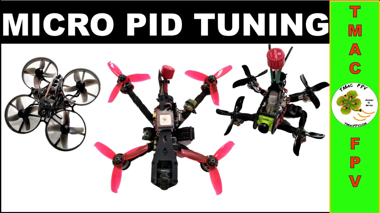
Betaflight filters eliminate unwanted vibrations and signal noise from gyro systems, improving flight smoothness and reducing motor temperatures. The Gyro RPM Filter (enabled at value 3) generates 36 notch filters across all axes to destroy motor noise based on individual RPMs. The Dynamic Notch Filter (width 0, Q 250, min 100Hz, max 200Hz) addresses residual noise and frame resonance. Low-pass filters balance filtering effectiveness against propwash handling; moving sliders right reduces filtering but increases motor temps. Default values of 1.5 work for most quads, with incremental adjustments recommended if needed. This filter configuration forms the foundation for smooth micro FPV flight.
Click to watch →
Betaflight RPM Filter (SMOOTH FLIGHTS!)
11.8K
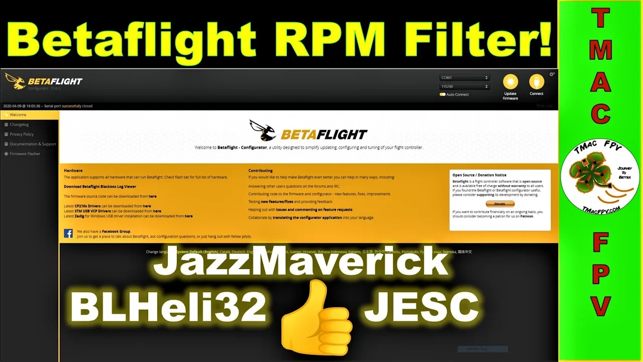
Final step involves configuring Betaflight for RPM filtering. First, determine motor magnets count from specs or physical count. Then configure: set motor polls/number of magnets, set gyro/PID to 4000 Hz, ESC protocol to DShot 300, enable bi-directional DShot. Verify motor balance with props off - error rates must be 1% or less. Configure filter settings: enable gyro RPM filter, set dynamic notch to medium, width 0%, Q 200, min 150. Fly and monitor motor sounds and temperatures. Adjust filters if needed to reduce latency based on flight performance.
Click to watch →
Deep Dive
Applied mechanical design for vibration isolation, involving the study of dampening coefficients and calculating resonance frequencies for custom-engineered camera mounts.
BetaFPV Pavo30 reviewed, analyzed and tuned. It flies so much better!
18.5K
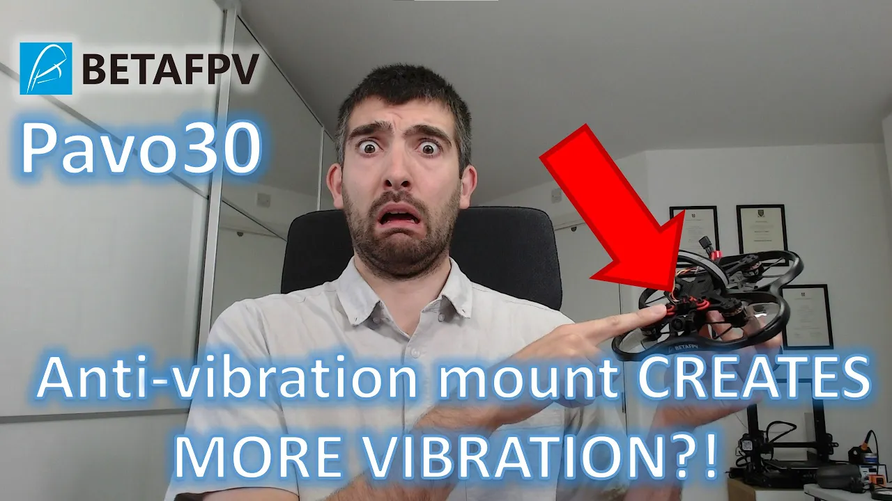
Harmonic analysis reveals that the camera mount's flexibility causes resonant peaks at 33 Hz (forward/backward) and 50 Hz (left/right). The silicon gummy mount has a damping ratio of 0.05-0.1, which amplifies rather than attenuates vibrations at these frequencies. A well-designed vibration isolation system must place prop wash frequencies (up to 80 Hz) below the amplification region and motor frequencies (60th of RPMs) above it, with damping ratio close to 1. The Pavo 30's amplification region sits directly on prop wash frequencies, making the problem worse.
Click to watch →
21. Vibration Isolation
150.6K
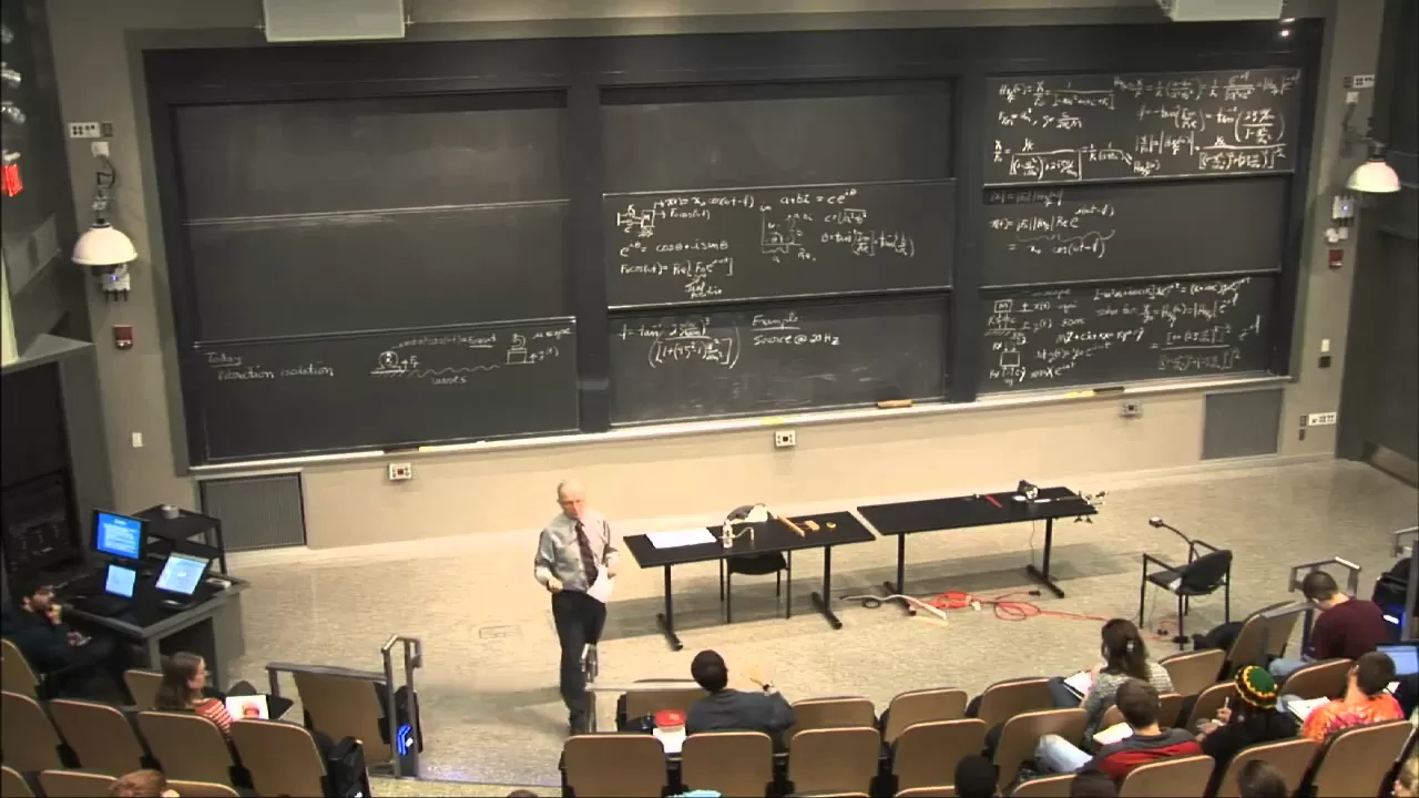
Damping affects vibration isolation performance differently depending on the operating region. At steady-state high frequencies (ω/ωₙ >> 1), more damping degrades isolation performance (makes the magnitude curve higher). However, some damping is necessary for practical systems because: (1) During startup, the system must pass through resonance, and damping prevents excessive transient vibrations, and (2) Without damping, initial conditions cause persistent oscillations at the natural frequency.
Click to watch →

Force vibration problem with transmissible force - Dynamics of Machinery (DOM) in Tamil
43.3K
This section presents a practical vibration isolation problem: a 100 kg compressor with 2 kg reciprocating mass and 80 mm stroke, supported by four springs. The design requirement is that transmitted force equals 1/25th of impressed force. The solution involves calculating stiffness and damping values. When damping is added, amplitude reduces to 25% of original (X1 = 0.75×X2). The damping ratio ζ is determined from the amplitude reduction relationship, enabling calculation of the required damping coefficient for effective vibration isolation.
Click to watch →

07 Kuliah Getaran Paksa
894
For vibration isolation, design criteria are: (1) Frequency ratio r > √2 for effective isolation (T < 1), (2) Damping ratio should minimize resonance peak, (3) System should operate in region where amplitude ratio is below desired limit. The amplitude ratio is X/Y = √[(1 + (2ζr)²) / ((1 - r²)² + (2ζr)²)]. For a design problem with m = 2000 kg, Y = 0.2 m, X = 0.1 m, ω = 157 rad/s, the solution involves finding k and c that satisfy the amplitude limit. The design involves balancing stiffness and damping to achieve desired isolation performance. The design constraints are: k < 17 MN/m (stiffness limit), c > 31 kN·s/m (damping limit). These constraints represent the fundamental trade-offs in vibration isolation design.
Click to watch →
Retropower Uncut Episode 52: One Year Of Blundering Around The Workshop With a Camera!
37.2K
Vibration damping materials like Dynamat are applied to reduce resonance in vehicle shells. Application areas include underneath floor plates, inside quarters, inside the roof (where headlining will be installed), and inside doors. This treatment is particularly important for competition-spec cars that may not have the refinement of road cars. The goal is to reduce horrible resonance while maintaining the car's performance characteristics. Any area covered by trim panels or headlining that won't be visible in the finished car is a candidate for treatment.
Click to watch →
Deep Dive
Comparative analysis of hardware-level physical stabilization (such as mechanical gimbals or wire-rope isolators) versus software-level post-processing.

GoPro: Tip #105 Post Production Stabilization or Gimbal?
1K
Video stabilization can be achieved through two primary methods: post-production stabilization using software like Adobe Premiere or Final Cut, and physical stabilization using a gimbal (an electronic stabilizer attached during recording). While post-production stabilization can effectively reduce camera shake, gimbal stabilization provides superior results by preventing shake at the source during recording, resulting in smoother and more professional-looking footage.
Click to watch →

Insta360 GO 2 vs GoPro Hero 9 - Stabilization Battle
12.2K
This segment compares Insta360's Flow State electronic stabilization against GoPro's HyperSmooth hardware-based stabilization. The video demonstrates that electronic stabilization cannot handle all vibration types, showing that mechanical gimbals remain necessary for extreme conditions. The comparison reveals that while hardware stabilization requires additional weight for gimbals and dampers, software stabilization achieves similar results without the extra weight. The video also covers ND filter usage for exposure control in bright conditions and demonstrates the magnetic mounting system using rare earth neodymium magnets.
Click to watch →

Sony ZV-1 Image Stabilization Options - Do You Need a Gimbal?
12.3K
This segment presents a systematic comparison of three stabilization approaches for the Sony ZV-1: in-camera electronic stabilization (SteadyShot), post-processing stabilization via Catalyst Browse software, and mechanical stabilization using a gimbal. Through controlled tests including normal walking, walking while talking, running, and controlled 'Ninja Walk' scenarios, the video demonstrates how each method performs under different movement conditions. Key findings reveal that in-camera stabilization provides consistent improvement for everyday use, post-processing achieves comparable or slightly better results but introduces artifacts, and gimbals deliver superior stabilization with clean image quality. The analysis emphasizes that each method involves fundamental trade-offs between stability, image quality, workflow complexity, and portability.
Click to watch →
SONY ZVE10 STABILISATION - Gimbal or Software?
181
This video explores video stabilization methods through practical demonstration. The presenter tests the Feiyu G6 Max gimbal with a Sony ZV-E10 camera, revealing key trade-offs: hardware gimbals provide real-time stabilization but require 5+ minutes of setup, careful balancing, and cannot directly control the camera. Software alternatives like Lumafusion's Lock and Load feature offer post-production stabilization but may be less effective. The presenter demonstrates both approaches during a countryside drive, highlighting that hardware gimbals suit dynamic filming while software works for static shots. The video emphasizes that stabilization method selection depends on filming context, equipment constraints, and post-production availability.
Click to watch →

HTN StockCast - We take a look at the all new Scorpion 3.0 Remote Mounted Solution
1.6K
The Spiderbot system employs hardware stabilization through a three-axis gimbal, which provides complete stabilization without lag or field of view reduction. In contrast, software-based image stabilization narrows the field of view because it must use a smaller subset of the image to achieve stabilization. Software stabilization works by cropping the image to a smaller center portion and then stabilizing that subset, similar to how older VHS displays would bounce around the screen. This creates a small amount of lag because the software must process the image in real-time. Hardware stabilization, while more complex, provides superior results without these trade-offs. The difference is noticeable when switching between the two types, with hardware stabilization being the preferred choice for demanding applications.
Click to watch →
Deep Dive
Exploration of open-source stabilization alternatives like Gyroflow, including how to extract, parse, and manually synchronize raw blackbox gyro data with non-native camera systems.

Blackmagic can use Gyroflow now! Tutorial pt.1
10.9K
Gyroflow is an open-source video stabilization software that can now stabilize raw files from Blackmagic cameras by reading embedded gyroscopic data; the process involves updating camera firmware, configuring camera settings (raw codec, 4K DCI resolution), converting raw files to intermediate formats like DNxHR in DaVinci Resolve, loading the converted video and raw gyro data into Gyroflow, setting sync points to align gyro traces with video movement, and adjusting stabilization parameters including field of view and smoothness before exporting the stabilized footage.
Click to watch →
Stabilize FPV Video (FREE GYROFLOW SOFTWARE!)
14.5K
This video tutorial demonstrates how to stabilize FPV drone video for free using Gyroflow software by synchronizing flight video with Blackbox log files. The process involves: (1) recording flight video and Blackbox log files with proper settings (500-1000Hz logging rate), (2) converting video to MP4 format if necessary, (3) synchronizing video with Blackbox log by arming the quad in front of the camera and noting the offset time, (4) exporting CSV files from Blackbox Explorer, (5) using Gyroflow to upload video, CSV, and camera-specific lens presets, (6) inputting gyro offset values and sync timestamps, and (7) exporting the stabilized video. This method works with any FPV camera and eliminates the need for expensive external cameras or paid stabilization services.
Click to watch →
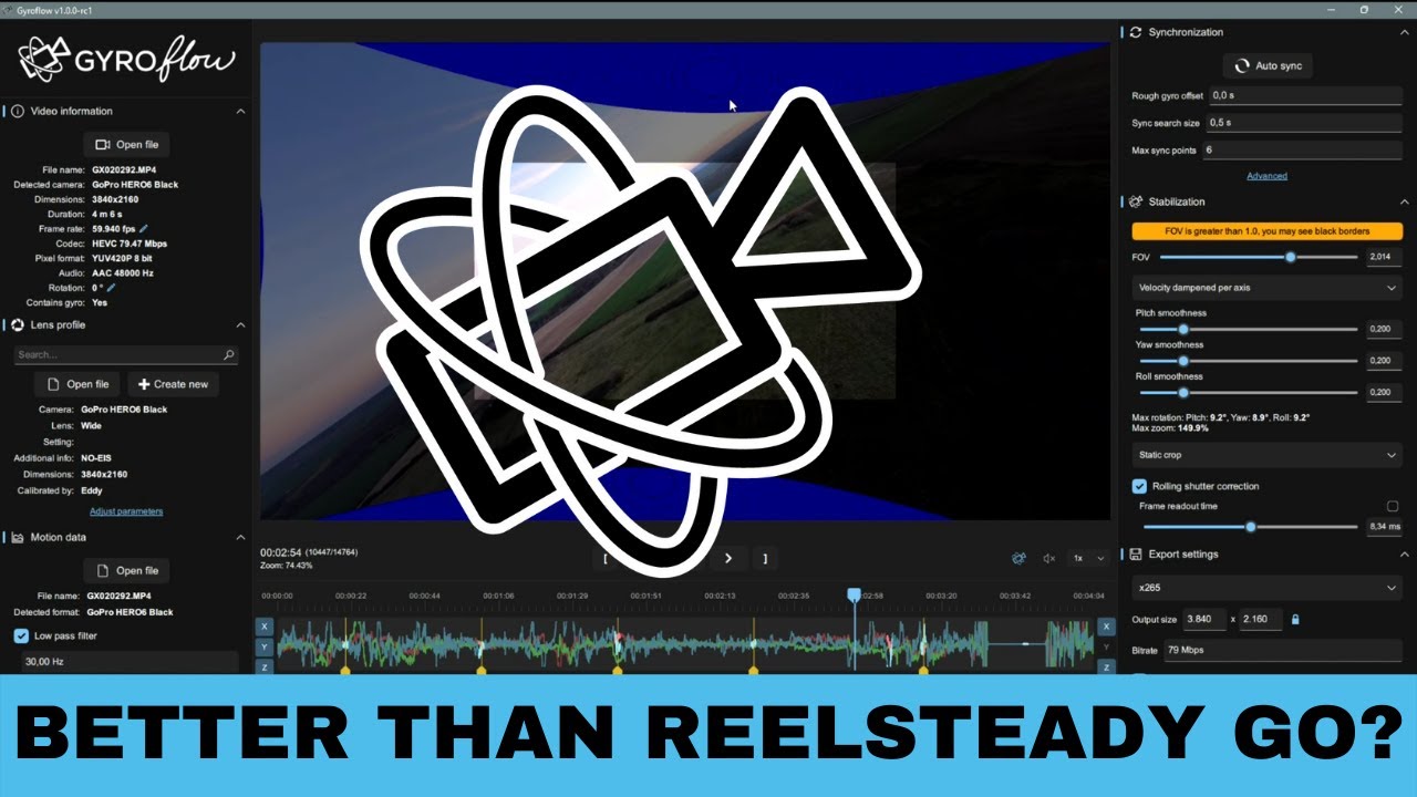
Gyroflow 1.0.0 - In depth guide how to stabilize GoPro Footage
21K
Gyroflow is a video stabilization software that uses internal gyroscopes of action cameras to stabilize footage, offering an alternative to image-analysis-based methods. The software supports cameras with integrated gyroscopes (GoPro Hero 5+, Insta360, RunCam Orange, DJI Action Cam) and can also use black box data from flight controllers for cameras without built-in gyros. The interface includes video information panel, real-time preview, motion graph comparing gyroscope and optical flow data, and stabilization settings. Synchronization aligns gyroscope data with video using auto sync, which finds matching patterns between image movement and gyroscope data. Sync points are markers where Gyroflow detects clear movement for synchronization, with the number needed depending on camera model and firmware version.
Click to watch →
Next-Level-Videostabilisierung GRATIS mit diesem kostenlosem Plugin!
23.1K
Gyroflow is a free tool that utilizes gyroscope metadata from cameras to stabilize video footage accurately and quickly. It serves as an alternative to traditional stabilization methods like sensor or lens stabilization. The tool works with specific camera models that record gyroscope metadata, including action cameras from DJI and GoPro (recent models), Sony cameras starting from the A7S3, Blackmagic cameras, RED cameras including the Komodo, and some FPV drone cameras. The fundamental requirement is that the camera must be able to record and process gyroscope data. Gyroflow offers standalone software for Windows, Mac, Linux, and mobile devices, as well as plugins for Davinci Resolve and Final Cut Pro.
Click to watch →

Идеальная стабилизация для DJI Air Unit , этот вариант Работает.
9.8K
This video demonstrates how to solve video stabilization issues on DJI Air Unit by using gyroscopic data recorded from a BlackBox flight controller instead of the camera's built-in gyro data. The presenter explains that the vertical vibration artifacts in standard Gyroflow stabilization occur because the Air Unit's gyroscope was designed for DJI Neo drones with mechanical vertical stabilization. By recording gyro data at 500 Hz using BlackBox, configuring it to start recording when the drone arms, and then applying this data in Gyroflow with auto-synchronization settings, the video achieves significantly clearer stabilization results. The process involves configuring BlackBox settings, extracting flight data files, and applying them in Gyroflow with proper synchronization parameters.
Click to watch →
Mount Design
Flight Test
Mount Design
0:00- 1
Showcases a custom anti-vibration mount.
- 2
Uses 3D-printed base and TPU top secured with cable ties.
Rigid Mounting and Digital Filtering vs. Mechanical Soft-Mounting
While soft-mounting is intended to mechanically dampen high-frequency vibrations, a strong counter-argument exists in favor of rigid mounting paired with digital filtering. Critics in the FPV community point out that soft-mounting can introduce unwanted mechanical play, phase delay, and low-frequency resonance. Specifically for post-stabilization software like Reelsteady GO, which relies on precise synchronization between the gyro sensor and the camera, soft-mounting the camera independently from the flight controller can actually degrade stabilization quality. If the camera wiggles on a soft mount while the gyro remains rigidly attached to the frame, the gyro data no longer accurately reflects the camera's actual physical motion, leading to stabilization artifacts or 'jello' effects. Consequently, many experts advocate for a structurally rigid drone frame, balanced hardware, and advanced digital gyro filtering (such as RPM filters) as a more reliable approach than mechanical dampening.
Understanding of drone propulsion dynamics, specifically how brushless motors and unbalanced propellers generate high-frequency mechanical vibrations.
Basic knowledge of IMUs (Inertial Measurement Units), particularly how gyroscopes record angular velocity and how physical vibrations introduce noise into this sensor data.
Familiarity with 3D printing filaments, specifically the mechanical differences between rigid plastics (like PLA) and flexible elastomers (like TPU) used for shock absorption.
The core concept of gyro-based video stabilization, which requires clean, uncorrupted gyroscope log data synced to video frames to computationally remove camera shake.
Advanced flight controller signal filtering, including the configuration of RPM filtering and Dynamic Notch Filters in Betaflight to software-filter residual noise.
Applied mechanical design for vibration isolation, involving the study of dampening coefficients and calculating resonance frequencies for custom-engineered camera mounts.
Comparative analysis of hardware-level physical stabilization (such as mechanical gimbals or wire-rope isolators) versus software-level post-processing.
Exploration of open-source stabilization alternatives like Gyroflow, including how to extract, parse, and manually synchronize raw blackbox gyro data with non-native camera systems.
329 views7likes3:24@thumbjuggler3943Original Release: 2020-01-23
okay so this is the Beast it needs a bit of TLC at the moment but I just thought I'd show off my anti vibration mount that I've created so there's a 3d printed bit at the bottom and then cable ties that secure the TPU printed top section seems to work so far I'll show you some flight footage now [Music] [Music] [Music] [Music] [Music] [Music] [Music] [Music] [Music] [Applause] [Music]
Up Next
61:19
Building a 200 MPH FPV Drone: AOS-HS5 Assembly Guide
@JoshuaBardwell
125.4K views•2024-11-11

12:54
Triumph of Orthodoxy Icon: Byzantine Art & History Explained
@BenCallan
2.1K views•2024-08-06

9:49
FastAPI vs Flask vs Django: Choosing the Right Python Web Framework
@TechWithTim
302.5K views•2024-05-26

1:42
Game of Thrones Opening Credits: A Cinematic Analysis
@gameofthrones
46.3M views•2011-04-18
Related Study Plans & Knowledge Roadmaps
Structured learning paths in General & Interdisciplinary Studies
general-studies
Elevator Engineering: History, Physics & Cities
01From Hoists to Safety Brakes: The Dawn of Vertical Lift
02Hydraulic vs. Traction: The Engineering Physics of Elevators
03Modern Speed, Safety, and Algorithms
+ 2 more learning modules
12h5 modules
Explore Roadmap
general-studies
Rubber: Material Science, History & Geopolitics
01Origins of Natural Rubber & Mesoamerican History
02The Chemistry of Natural Rubber & Vulcanization
03The Geopolitics of the Rubber Boom & Colonization
+ 2 more learning modules
12h5 modules
Explore Roadmap
general-studies
Containerization: Evolution, Logistics & Trade
01Ancient Trade & Bulk Cargo: Amphorae to Barrels
02The Industrial Revolution & Cardboard Packaging
03The Containerization Revolution: Malcom McLean
+ 2 more learning modules
12h5 modules
Explore Roadmap
general-studies
Textile Tech: Evolution, Labor & Global Impact
01Pre-Industrial Textiles: Handloom & Cottage Industry
02Mechanization: The Spinning Jenny to the Power Loom
03The Factory System & Global Labor Transformation
+ 2 more learning modules
10h5 modules
Explore Roadmap