![[SOLDERING STREAM] Learning to solder :3 Results may vary ✨](https://i.ytimg.com/vi/TdJvYGc1sis/maxresdefault.jpg)

















![How to program a Castle Creations ESC without a Castle Link or Field Card [Tutorial]](https://i.ytimg.com/vi/0EMxy7dBTVE/hqdefault.jpg)

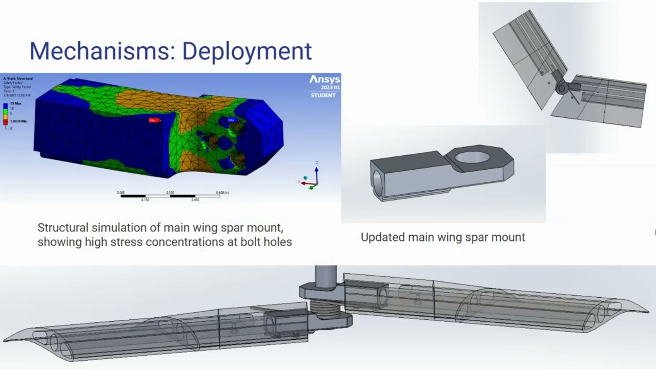


Building a 200+ MPH drone requires specialized components including high-KV motors (T-Motor Vilo 2808 1950KV), high-pitch props (HQ 5.3x8 thin electric), 8S battery packs, and bulletproof ESCs, combined with aerodynamic optimization through custom 3D-printed fairings that reduce drag, which increases as the cube of speed; the build also requires careful attention to electrical connections, motor direction setup in pusher configuration, and proper capacitor installation for stable power delivery.
Building a 200 MPH FPV Drone: AOS-HS5 Assembly Guide
Added:Fundamental electronics and soldering techniques, including understanding voltage, current, polarity, and cold solder joints.
Basic architecture of FPV drones, specifically the functions of and connections between the Flight Controller (FC), Electronic Speed Controller (ESC), motors, receiver, and video transmitter (VTX).
Lithium Polymer (LiPo) battery safety, handling, and power management, particularly regarding high-voltage (6S+) power systems.
Basic concepts of propulsion and aerodynamics, such as motor KV ratings, propeller pitch, and thrust-to-weight ratios.
Advanced Betaflight PID tuning and Blackbox log analysis to optimize flight stability and minimize oscillations at extreme speeds.
Aerodynamic optimization and drag reduction techniques for quadcopter frames and components operating at high velocities.
Advanced ESC configuration and firmware customization (e.g., custom motor timing, PWM frequencies) to squeeze maximum efficiency from the propulsion system.
High-speed piloting techniques, specialized safety protocols, and regulatory compliance for operating high-velocity unmanned aerial vehicles (UAVs).
125.4K views3.3Klikes1:01:19Original Release: 2024-11-11
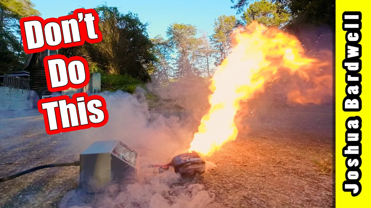
how would you like to build a drone that could go over 200 miles an hour yeah well we'd all like to build a drone that could go over 200 miles an hour but it's not easy to make a drone go that freaking fast you can't just buy a pile of Parts slap them together on a bench and go 200 M an hour or can you this is the AOS hs5 and it is a new drone design from Chris Rosser the HS stands for highp Speed and what he's done is designed a drone that can go 200 plus miles an hour out of the box so that all you have to do is buy the parts put them together just like you would any other drone Take It Outside Peg the throttle and you're going 200 mil hour at least that's what he says and we're going to find out today cuz we're going to build one and I'm going to take it outside and I'm going to fly it we're going to see if it goes 200 miles an hour I'm Joshua Bardwell you're going to learn something today yeah that's a little what the [ __ ] oh [ __ ] why why did it disarm please don't have broken the whole thing exploded the whole thing just exploded into a zillion pieces that's it I know that if you come to watch a video about building a 200 mph quadcopter then obviously you are expecting that by the end of the video you will see the quadcopter go 200 miles an hour I um I have to tell you straight up here at the beginning that that's not going to going to happen this is a build video and there's going to be a little bit of flight at the end but it will not be flight of me going 200 mph it will be a flight of me learning something that I didn't know about beta flight that resulted in uh this quadcopter crashing and as you can see it is you can't crash a 3D printed shell and have it survive at all so this is the part of the video where I would show you footage of someone going over 200 mph with an AOS H S5 but there's one problem there it's not legal to go over 200 mph in the United States without a waiver from the FAA and they don't give out very many if any of the waivers so uh there is no way I would show you the GPS data showing that this drone is going over 200 M hour nor would I ever be able to even say where this footage came from or where it was taken I would just say isn't it interesting that there's some pretty footage being taken by some drone somewhere going some speed uh and then I would get on with the video this stuff right here is what you get when you buy the AOS hs5 kit it's some custom 3D printed Parts including a fairing uh and in case you didn't know aerodynamics is extremely important when you're trying to go over lets I mean it's important at any speed but the faster you go the more important it is because drag increases as the cube of the frontal area So the faster you go the more drag there is and aerodynamics is extremely important you might be surprised to to learn that the top speed records are not being set with 10s 12s it used to be that people thought that if you were going to break a speed record what you do is you take a motor and you just ramp the voltage up and you ramp up the RPM until it goes screaming fast but there's a limit to how far you can get with that approach if you design the quadcopter right if you have the right if you have the right aerody Dynamics you can actually go ridiculously fast on relatively sedate equipment so you get these 3D prints that do the aerodynamic work for you Chris has done all the engineering there and you get this plate which is going to hold the electronics and you get oh you put it all together and then you've got a 200 mph drone got to get this out of the way here at the beginning the STL files for these 3D prints are not published you can't get them you can't buy them you can't have them if you want these 3D printed Parts you're going to be ordering them from brain 3D and brain 3D are good people it's got nothing against them and well frankly Chris rosser's good people too but as a person in the 3D printing World it pisses me off it's not even about the money if I break this canopy I got to wait for brain 3D to ship me another one when I could just be printing it on my own printer oh it's printed out of I don't know what this is or what if I want to print it out of nylon or some other what if I want to try something else what if I want to remix it can't do it he's not publishing the stls that sucks I hope he changes his mind I know he's got to make his money I don't blame him for that and I just wish that we could think of a way but let's face it as soon as he publishes the stls nobody's going to freaking buy them so I kind of see both sides of it just want to get that out of the way though okay so that's the frame and the canopy what about the rest of the build and the rest of the build is going to look pretty similar to any other copter that you would have built with a few little differences the motors are t-motor vilo 2808 Motors in 1950 KV and you might be thinking 2808 that feels like a 7in or an 8 in prop but it's not it's a 5in prop uh we're going to be running these motors on 8s voltage to get the you can build this on 6s if you don't feel like going to 8s but I want the maximum speed possible and in order to run these motors at these ridiculous LLY high RPMs we're going to need a bigger motor to help soak that heat and dissipate that heat with more surface area so this is a 2808 motor running a 5 in prop what prop is it going to run and this is another place where high-speed records require a lot of refinement because you can slap a typical 5-in gem fan or HQ prop on uh quadcopter and you could run it at ridiculously high RPMs and you just won't get the kind of speed that you need need you really have to get a prop with the right pitch the right stiffness and so on here is the prop that Chris has decided is the best the prop is the HQ 5.3 by8 thin electric prop and if you are used to typical freestyle and racing props the pitch on this prop is really going to take you by surprise typically the pitch on the props that we use for freestyle and racing is in the 3 to five range a pitch of eight is ridiculously high and that's because the faster the oncoming Airstream the higher the pitch of the prop needs to be in order to generate thrust so this is a prop that is optimized for going flat out at 200 M an hour it's kind of like a bicycle with very high gearing where it's very difficult to get moving but then once you're moving it's a lot easier to keep moving because the gearing is so high that's not a great analogy there's a lot more going on with prop pitch than just thinking of it like gear but it's a little bit suitable and I would highly recommend you use this exact prop if you're going to follow along with this build this is an area where people who are trying to break speed records do a lot of iteration and a lot of testing to find the exact right prop that's going to give them the results that they need and you can get big differences in performance by going to a prop with slightly different characteristics Chris has already done that work for us so let's start out by taking advantage of his research as I said before we are going to be using an8 cell battery to get the maximum speed out of these motors and this exact GMB 1100 mAh battery is just about the biggest battery that will fit inside this canopy the batter is actually going to go down in there and you can see we've got a little room to spare but obviously we can't just make batteries of arbitrary Dimensions um this is really the battery that you're going to want to go with if you're going with an 8s the actual dimensions of the battery Bay are 90 mm tall by 40x 55 mm Square so if you're shopping for a battery and you're not sure if it's going to fit compare it to those dimensions and if it's any bigger you probably can't use it every time I talk about 8s batteries people ask what charger do I use to charge the 8S batteries this isn't really specific to this build but I know you're going to ask so the charger that I use is the isdt air8 uh this is well until very recently this was the most economical charger that you could get that would charge 8s batteries there's actually a new one out I think from Hoda and I've seen people mention it but I haven't tested it if I can find a link to it I'll put it in the links in the video we're going to have links to all these parts in the video description below so if you're going to follow along and buy this stuff go down to the video description and check out those links if I can find that other Hoda charger I think it's a little cheaper and is being held up as an another alternative for ads charging so that's the motors and the battery now we come to the ESC and I got to tell you for this build you do not want to cheap out on the ESC yeah you probably could get away with using a good inexpensive ESC but I don't want to take take any chances we're going to be thrashing the [ __ ] out of this ESC and especially if we go ads we're really going to be thrashing it so I've gone with the foxier reaper F4 ESC here are the specs for this ESC for those who Wonder 65 amp rated 4 in1 BL ESC uh and honestly this is one of the most bulletproof esc's on the market uh and I think if anything can take the kind of abuse we're going to give it fingers crossed this will do it you don't have to use this exact ESC there are other good quality 8s CC's out there uh this was also just the one that I could find in stock so I went with it when it comes to the flight controller you've got a little bit more flexibility it is going to need to be 30 mm mounting that's also true for the ESC this Frame is designed for 30mm Hardware um and if you're going to run 8s you are going to want a flight controller that is rated for 8s voltage you could get a 6S rated flight controller and run it off a voltage regulator but that's kind of a pain in the ass I've done that for the voltage regulator itself is like a $25 part it adds uh weight it adds complexity and frankly it's so much easier just to get a flight controller that can take 8s natively and then everything just goes together like normal the flight controller I've settled on is not the foxier reaper flight controller in part because I don't think I could find the 30mm fox Reaper in stock and in part because I really wanted to try this the rotor Riot Brave F7 this is rotor Riot's new USA manufactured flight controller uh and amazingly it is 8s rated uh and has plugs for all of its connections and yes we are going to have to customize the plug between the ESC and the flight controller to make sure they're compatible I think maybe we'll luck out and they'll be compatible but I think it's going to be worth it and I'm really looking forward to trying this flight controller out finally we come to the video system and unfortunately we only have one choice for video system at least as long as we're using the AOS hs5 uh canopy uh Chris russer has designed this canopy around the DJI O3 air unit and the thinking is that the goal of this kind well my goal is just to go really fast and go woohoo but the actual goal of someone in real life who is building a drone like this would be probably to get some kind of cinematic shot you want to be able to chase a car at 200 M an hour and get a like a usable commercial shot and the DJI 03 air unit is capable of doing that without having to incorporate a GoPro or other HD camera into the build so in order to keep the build as light as possible and still be able to get decent quality cinematic footage we're going with the DJI 03 air unit if this was published then people could modify it to hold other cameras and that would be cool but it's not so you can't next we're going to mount the ESC and the motors to the carbon fiber plate and I'm already starting to see a problem that I'm going to need to solve related to my ESC selection you see the way that this is going to work is the ESC and the flight controller are going to go on top here and the motors are going to go on the underside this is going to be a pusher configuration and the battery is going to go underneath so what needs to happen is that the xt60 needs to come out the bottom so that then when the battery comes up xt60 goes down and plugs in and what you would normally do you would just solder the xt60 to the underside of the ESC but if we look closely at this ESC we can see ha there are no solder pads on the bottom so we have two choices well we could just Mount the ESC upside down but then that's going to make it hard to solder the motors on because the ESC solder pads are going to be up against the carbon that's a non-starter so then I guess what we need to do is solder the xt60 like that so it's going to come around I think that's what we're going to need to do yeah and that's going to be tricky because as you see when you tin the wire the solder Wicks up into the wire and makes a stiff spot I guess the xt60 doesn't need to be super long so I'm going to try and cut the pre tinned wire off and start from scratch and what I'm going to do is before I tin the wire I'm going to bend it at a 90° angle I'm going to see if that lets me solder this on coming straight out the bottom well may need a little bit of spacing there but I think we can make it work the ESC comes with two sets of gummies and one of them is this little thin one and one of them has this additional spacing I'm going to try using the one with the additional spacing to give us that just a little bit of separation between the ESC and the bottom temp plate uh and hopefully that will make everything work I can get away with that like normally maybe one of those would be for the ESC and one would be for the flight controller but the rotor Riot flight controller also comes with its own set of gummies and so I don't uh I don't I can I can use them as spares you can find the front of the frame by looking for this M3 hole in the center and there's two here in the rear the ESC has a forward-facing arrow here so this xt60 is going to go in the rear we're going to just slide that through here and we're going to gently slide the gummies down onto the M3 stack screws and cross our fingers that when we press that down everything will work out okay so far so good and I think we're going to have enough room on the top of those screws to for the flight controller we'll find out when we get to that part of the build next we're going to mount the motors and there are a couple little quirks here compared to how you normally build a quadcopter the first little Quirk is that this is a pusher build and that means that the motors are going to go on the underside of the arm not the same side as the ESC don't build them like this you'll have to redo it and the second little Quirk is that the motors are going to have these fairings on the underside to help increase the aerodynamic decrease the drag increase the aerodynamics of the quadcopter and help it go fast and you may think well how much difference could that little fairing make but the reality is that most of the drag happens on the back side obviously having an A A streamlined front side is important too but having a streamlined backside is important as well uh so uh these fairings are going to help uh just that little bit now the good news is that the motors come with a set of motor screws but the bad news is that those motor screws are not the correct length you can see here it does not protrude out the top of the arm so we are going to need to Source our own set of 16 cap head motor screws how long are those screws going to need to be let's find out these screws that come with the motors appear to be 8 mm in length I'm going to guess we need another 2 mm so I'm going to try tens dang it I've clearly had this problem before those are my tens I'm out of tens I've used up all my tens can I use twelves I don't even think I have 16 12s I might tw's are going to be too long dang it oh maybe not Maybe not maybe 12's going to work well it's impossible for me to get this on camera but 12 appears to be the exact perfect length so you're going to need 16 12 mm M3 cap head screws now you can see that the screw is going to go down inside here it's going to come up through and then it's going to tighten down against the plastic of the fairing so as you can imagine if you were to just crank this screw down infinitely tight you would just rip through the the plastic and you would destroy everything so don't do that but the other concern you might have is that how am I going to make sure that my screws are tight enough that they don't back out and anytime I'm using any kind of motor mount or fairing any kind of 3D printed accessory where I don't have metal on metal and I can crank it to the proper torque I'm always going to use Loctite little bit of blue Loctite on these is going to help make sure they don't loosen up very important some people would say It's always important but uh those people are weirdos the other problem we need to solve is that we need to get the motor wires over to the underside of the arm or the top of the arm the motors on the underside we need to get the motor wires over to the other side of the arm so that they can get to the ESC and we don't want a situation like this number one it's ugly number two it create it's a durability issue and it's an aerodynamic issue too so what we're going to do is we're going to just hand press the motor up against the arm and then we're going to bend this down I know this feels like you're breaking the motor but you're not you're going to bend this down so it fits into this Notch here and the wires are just going to come out of the motor at a 90° angle like so that's what we want motor goes here screws get locked tight and we're just going to start with the one outermost screw I think bearing goes on the arm Loosely screw we're going to just start the screw and we got to get everything sorted out here getting this mounted seems like it's going to be a pain in the butt what I have to do is I have to get the motor in place Bend these wires down and then the fairing has to go over the wires so they stay on the inside like that and then these wires are going to come out under here although I'm not too worried about that right now I'm just going to kind of gently squeeze everything together like so that's fine but now I have to get that screw started in the motor hopefully it's all lined up correctly right I don't know I got to look I can't show you there's no freaking way I can barely see okay there we go okay there's my screw there's my motor base wiggle come on baby grab threads oh it is it's grabbing yay okay okay I'm just going to Loosely install these three screws oh great it's only 12 screws it's not 16 cuz there's only three screws per motor ha yay I got to order more tens I'm going to Loosely install those screws and then I'm going to deal with the wiring when we're done mounting the motor here's what the build is going to look like uh we've got the fairing on top of the arm the motor on the bottom of the arm everything is neatly pressed together and no wires are pinched or snagged in any way everything is ready for us to solder to the ESC I I also see that that little speech I gave you about aerodynamics mattering on the rear of the build because drag happens at the rear too that's all true but I also see that this fairing is on the top or the front of the build and so that little speech was a little bit misplaced now we've got all four Motors installed and soldered neatly to the ESC do be careful because you're not going to want to have too much spare wire hanging out inside here I'm not sure exactly how tight this fairing is going to be but you can see it's going to be fairly tight you're not going to have a ton of room to play with and we've also got these screw holes here which presumably something's going to go in there so definitely just keep your wiring as neat and tidy as it can be this is not probably going to be your first build this better not be your first build next we're going to install the bottom fairings uh and the first thing you're you're going to do is get yourself some double-sided tape and cut yourself a piece of double-sided tape the length and width of the fairing then you're going to notice that one end of the fairing is slightly wider and one end of the fairing is slightly narrower I'm not sure if you can see it very well on camera this is the wider end and this is the narrower end and the narrower end is going to go toward the motor and The Wider end is going to go toward the center you're going to want to place the bottom fairing such that is about 1 to 2 mm away away from the motor you need enough clearance that the motor isn't going to rub but you want it to be fairly close and maybe you could even take this top part and just kind of slide it down to see how that's going to fit oh it's going to go on the other side fine yeah yeah okay so there shouldn't be any interference there I wonder what that one to do why like why wouldn't you put it here I guess you want good aerodynamics and good aerodynamics means that everything is you know sort of tight and neat we'll just go ahead and stick that down make sure it is smooth and flush and we're good to go finally we're going to get some electrical tape and we're just going to wrap that to hold everything together uh I'm tempted to use a zip tie but it seems like a zip tie would be like aerodynamically worse because it would stick out and like how much does that matter I don't know at 200 M hour it might matter a lot when we're done the result will look like this and I'm going to do three more off camera now we're going to begin to prep the flight controller for installation in the quadcopter and one of the characteristics of the rotor Riot Brave flight controller that makes it really suitable for this build is that it has plugs for all of its connectors um some flight controllers you're going to have to solder everything and some flight controllers have plugs for a few things but not for everything Chris Ruster strongly recommends that you plug all your peripherals even if you normally would direct solder because getting everything sort of jammed in here if it's all soldered together is going to be a little bit of a pain in the butt I'm going to take his for it that he wouldn't make that recommendation if it wasn't like really in everybody's best interest so I've got the plugs for the rotor Brave flight controller they come with it in the box and I've just kind of used common sense and trial and error to figure out where each one goes we've got the ESC plug here we have a plug for the GPS here um we've got a plug for the receiver here and it comes naked we'll probably going to direct utter that to the receiver because well I don't have no receiver with a plug and here here is the plug for the DJI air unit fantastic the first thing we're going to need to do is modify the ESC wiring harness because you can see here here's the pinout for the rotor Riot flight controller uh and you can see the pinout goes vbat ground current sense uh Telemetry and then 1 2 3 4 but if we look at the ESC you can see that the pinout goes ground vbat 1 2 3 4 and then current and Telemetry so if I were to plug PL this in notice that ground and vbat are swapped so we would just instantly fry the flight controller and the Telemetry of the motor signals are not in the right place we're going to need to repin this um done this before here's how it's not it's not pleasant what you have to do is very very carefully lift this retaining tab right here uh a very very fine pointed tweezer or like an xacto blade a very small hobby knife or something like that uh is the right tool to use you don't want to damage this housing although having some spare sh 1.0 housings around might be a good idea if you do this very often so I'm just going to very carefully try to get underneath here a little hard to do on camera apologize so I'm pushing it to the side try not to do that I'm at risk of breaking something there we go got underneath it lifted it up and then this pin should oh nope it's grabbed again dang it and this should slide right the godang there we go it should slide right out and then the next thing I like to do after I've done that is just very very carefully press that back down into place so that when I slide don't press it too hard or it'll break but just try and get that back where it goes so that when we put the next pin back in it'll slide in correctly and basically just one by one I'm going to pull these out and slide them back in until I have this the right way around the other thing I want to show you is that you can put these in upside down do you see the sort of shape of it right now the way that it is now is the way that it goes into the housing if you put it in upside down it will kind of not want to go in and then it'll it won't work right you got to put it in exactly like you see here with the little this little tab facing down and there's a little Barb on top that faces up and it goes in just like that again a little hard to do on camera but I will try so it goes in just like that it has to go in like that and if I just push that the rest of the way in you should hear a little click and if you tug on it it should not be able to be pulled out and you should see you see right here there's that little Barb you can just see it right there and if you pull on you can see it engaging with the retaining tab that is correctly inserted um if it won't fully insert you know you got to you got to you just got to make that happen so right here I've inserted this one and it's not grabbing see it's just I can just pull it right back out again and I'm going to guess that the reason for that is I have to push this tab down a little bit to get it back into position where it will grab so if I put push that down a little there we go now is it going to engage hasn't fully inserted yet doesn't want to fully insert there we go and yep there we go just a little jiggle but it is grabbing we need to do that for every single one I'm going to do it off camera when you're done here's what the result should look like and I strongly recommend that you do exactly what I've done here and literally plug the plug into the ESC and plug the plug into the flight controller and verify that everything checks out now on the flight controller side we don't have any labels we could get that document that I showed you on my phone but we know the flight controller side is correct because it came from rotor Riot and we plugged it in and we didn't change anything although it has happened that the wrong wiring comes from the factory or maybe you grabbed the wrong plug by accident so it would be good to just cross check that against the documentation vbat ground current Telemetry 1 2 3 4 and then on the ESC side we're going to do the same thing and again plug it in to the ESC because you can accidentally build the plug upside down but then when you plug it in it's the wrong way around you make all kinds of mistakes and I've seen them all and you're thinking I'm being over over careful overzealous here but I'm not trust me ground yes ground vbat black red 1 2 3 4 everything checks out this is what it should look like next we're going to do the GPS and you'll notice that the GPS plug has six positions but only four wires here's the reason for that the GPS that we're using is the matec M10 Q it is an M10 GPS which is the sort of latest technology going to give you the best performance compared to the older M8 and M9 GPS's that came before it and it has a buil-in compass and we know it has a built-in Compass because it has six wires ground da CL TX RX and 5vt the da and cl wires uh that is the interface to the compass and now there's some debate of whether we actually need the compass because we're going to be running betaflight on this and beta flight doesn't really do much with a compass if we were running inav or well we can't run RJ pilot on a on this flight controller but hypothetically if we were if we were running a flight Control software that had autonomous flight then we would want a compass beta flight doesn't really have a use for a compass so I'm probably just not going to wire up the da and cl wires I'll just remove them if you did want compass then you would need to well what what would you do you can actually buy pre crimped sh 1.0 wires I'll put a link in the video description to a wire assortment basically what you see here and we could actually take some of those wires and insert them into that plug and then we could have H we could have a working Compass I'm probably not going to go to the trouble of doing that though so the first thing I'm going to do is I'm just going to fold this wire harness in half and I'm going to cut it in half we're going to splice these wires together and it wouldn't hurt to have a spare wire harness I have screwed myself overd doing this in the past by not leaving myself enough wire but in this case I don't think that's going to be a problem and then we are going to remove the da and the CL wires and actually instead of cutting them off we can actually do the same thing we did when we were repinning the ESC we can just lift these little retention tabs and pull those wires out let me just double check the colors make sure I'm removing the correct wires da and cl are gray and green so there's our plug with the compass wires removed and then what we're going to do is we're going to splice that to the plug going to the rotor Riot flight controller let's see here just have to check the pin out to see what those wires are so here on the flight controller we've got 5 volts in ground obviously and then the green wire is rx and the blue wire is TX and remember that with a uart peripheral RX goes to TX and TX goes to RX so here on the GPS you can see that blue is TX and that's going to go to RX on the flight controller which is green so blue is going to go to green and yellow is rx which is going to go to TX yellow is going to go to blue blue on the GPS goes to Green on the flight controller yellow on the GPS goes to Blue on the flight controller I'll take care of that and I'll see you in a second and here's the result and as long as you don't see a clip right now from Joshua from the future telling you that I screwed up and we have to rearrange the wires then you can assume that this is correct next we're going to wire up the receiver and no surprise we're going to be using Express lrs the receiver we are going to be using is the radio Master rp1 uh that is going to go to this plug on the flight controller conveniently labeled RX and it's got four wires 5vt ground TX and RX presumably we'll just double check the documentation on the rotor Riot website and see that the blue one is TX so TX is going to go to RX on the receiver I'll probably have to recheck that when I solder it up and there we go our receiver is soldered up and ready to plug into our flight controller next we're going to get this plate Chris calls this the top plate although it's not very similar to a top plate in what most quadcopter frames we would be familiar with but this is the top plate and this is where we're going to mount the 03 and the receiver and uh this 3D print has come with it and it is not in the build tutorial that Chris roster made so I'm going to have to just figure out how it goes on there and I can pretty much tell that this is for the receiver antenna right yeah that goes in there this wire comes up here yep that's all fine and then where's the 03 it's a little unclear to me uh the 03 goes here oh I see so what's happening here is these holes there you can see are made to fit the holes on the 03 but the problem is that these are not M2 screws these are m1.6 screws if my memory is correct I don't have those to screw it down yeah those aren't M2 those are 1.6 I don't have any spare 1.6s to mount this with you would so we're going to do it the oldfashioned way um we should make sure that this screw hole is not obstructed because presumably that's going to be for something I need to work around those zip ties I think so I think what's going to work best is to run like a strip of tape like that in between the zip ties the receiver can go like that make sure not to pinch these coaxial antenna wires and then it will stick here like that yeah I think that's pretty good it seems all right we'll see what happens when I go to actually install it in the aircraft now in Chris roster's build video the next thing he does is he starts putting everything in the canopy and starts assembling the quadcopter but I think what I'm going to do is smoke check this and go configure the flight controller and make sure I've got all my wiring sorted out you see I've basically got a completely assembled quadcopter well not assembled but the electronics are put together and if I just plug the ESC in here then I can configure everything receiver GPS VTX I can do it all and then if there are any problems I can fix them before I put everything in the gosh dang quadcopter um I guess we should do a smoke check and I'll in order to help protect me I'll unplug everything first I can unplug things one by one that way if I fry something I don't fry everything this part should be easy because like what could possibly go wrong like what could I have screwed up okay good no smoke uh next we plug in the flight controller no smoke good next we plug in the GPS no smoke and next we'll plug in the receiver shouldn't be any smoke on that one receivers blinking good and the digital VTX it's all good no smoke at all let's head over to the computer and let's do the beta flight setup before we continue with the video I'd like to remind you that the single best way for you to help make sure that I am able to continue making content like this which hopefully you value is to join my patreon patreon is a website where you subscribe to me for as little as $2 a month that's the minimum amount just $2 a month uh someone's vacuuming but join my patreon get access to my Discord server and just feel good about supporting the work that I do here if you watch my content regularly uh then hopefully eventually you'll come to a point where you go this guy's earned my support if today is that day join my patreon at any level at any dollar value that you pick $2 pick $5 pick $10 pick whatever amount you think is fair for the amount of value you get out of my content there's a link down below below where you can click through and if today is not the day if you're like oh I just want to watch the video you've probably already skipped ahead but uh yeah keep watching the content I'll keep making the content and I hope that day comes there are going to be some parts of this configuration that I'm not going to show you because I assume that if you're building a quadcopter like this this is not your first build I'm going to focus just on things that are sort of unique to this build and this Hardware uh so for example I've updated the firmware on the air unit I've activated it I've bound it I'm not going to show all that stuff let's connect to the flight controller and just check and it does seem they're shipping it on betaflight 451 so that's the latest at the time that we making this video good on them for not shipping it with some older version we don't need to flash it and frankly even if it's the future and the 452 is out you may not need to flash it a lot of times it's better to just run what you know works but that's a decision you can make for yourself we're going to stick with 4551 uh we are going to now set up the receiver and in order to do that we're going to go to the ports tab receiver is on Art one we'll enable that and uh long as we're here GPS is on Ur 3 so we'll go ahead and enable GPS for art 3 and we'll do the video transmitter a little bit later um let's see well let's see GPS sure why not uh do we need to oh GPS is red that means we're talking to the GPS but we don't have a GPS lock that's good that's good just magically worked love it guess my wiring is correct um receiver receiver well I haven't bound the receiver but uh the default configuration is correct Telemetry is enabled I'm going to need to flash and bind my uh expresser receiver and I'm not going to show you that because again I assume if you're building a quadcopter this capable and advanced you already know how to do that I'll put a link in the video description to my how to bind Express lrs video if somehow you are building this quadcopter and don't know how to do that okay my receiver is flashed and bound it did take a while for the receiver to actually sync up there's actually a trick for how you can get your Express lrs receivers to syn up more quickly when they first power up I've made a video about it I'm not going to tell you about it now links in the video description below if you run Express lrs you should know this trick I don't think we should need to Turtle mode this if we have to Turtle mode this thing it's bad but I can't not put Turtle mode on one of my birds receiver GPS video transmitter so we're going to go to presets and as long as we're here we may as well load some other things my 533 racing rates okay uh Express is 250 Hertz yes with uh let's not have an ultra sharp let's do cinematic so we have smooth movement or was the4 dj3 okay uh yes correct the art number is going to be four art 4 that is it I believe while I'm in the presets tab I'm also going to search for the AOS hs5 tune R Chris roster has a pit tune here we go AOS hs5 200 mph tune by Chris Rosser we're going to apply That Tune let's see I've already done Els 250 HZ that's fine battery sag compensation recommended okay fine no stick deadband okay fine armad already did that and I'm not going to touch my motor Direction I already did that um so I already did that oh what the hell and pick and save and reboot the other thing we should do is because we're running on 8s we're going to go to the pit tuning Tab and Chris recommended we drop the master multiplier a little bit I don't know how much that is but I'm going to drop it to like 0.8 and save since we're running on 8s and then for the OSD rather than set up from scratch I'm going to go to this paste bin that I have where I have a saved config dump for my OSD settings I think this is going to have some bugs cuz it's from an old older version of betaf flight let's find out yeah just one bug maybe they've got it as its own option so we don't have any GPS options in here so we'll need to set those up GPS SATs oh in the middle of the screen let's see where do I want these GPS speed now GPS speed we want dead freaking Center home direction home distance I don't think are that important but on any GPS bird I kind of want to put them Just for just because where's hdop though why did beta flake get rid of hdop surely surely that's not right oh there it is pdop all right I don't care that's what I wanted now we're going to set up the motors and there's something you need to know about setting up the motors on a pusher quadcopter and that is that when we set the motor Direction and the motor position we need to have the motors in the orientation that they'll be in when the quad is going to fly so your natural inclination might be to set the quad cter like this and do everything like you normally would on a standard motor configuration that would be incorrect what we're going to do is we're going to set the quadcopter like this and we're going to do it this way so I'm going to go ahead and plug in and I guess I'm going to need to lift this up slightly so they're not buzzing on the table uh and we're going to do the let's see t-shot 600 yes bidirectional dshot we definitely want save and reboot next we're going to check the motor position so I'm going to hit the reorder Motors wizard I understand the risks and start and holding it in the inflight orientation we should see the back right motor is spinning and I'll click on that do you see that if I had it flipped the normal way that would be the back left motor and everything would be wrong front right back left and front left okay great that's all done now we'll do motor Direction and once again I go to the motors tab we'll do motor Direction I understand the risks we'll do the wizard to start spin Motors once again we need to do it facing this direction so I'm going to use this little brush to help you see which direction the motors are going motor number one should be going counterclockwise and it is do you see that if this was flipped over it would be spinning clockwise and everything would be wrong um except it wouldn't be the back left motor yeah anyway uh motor number two clockwise correct oh we're two for two oh motor number three uh clockwise no motor number three is going counterclockwise so we need to reverse it counterclockwise yes and motor number four should be spinning counterclockwise and it is we'll just double check here by the way when you install the props you also need to put them on upside down except upside down is right side up so here this motor is spinning props out so I'm going to take this prop and I'm going to put it on the right way up but it's going to go on the motor shaft the opposite way from how it would normally be so it's going to go on the motor like this and spin like this it is not going to go on the motor like this right that's up that's upside down right anyway okay Point made I mounted the flight controller in the frame off camera I think it's something you can probably figure out how to do uh you can see that I used the extra gummies from the ESC as spacers between the ESC and the flight controller uh I had to squish the stack just a little bit to get it on the screws but it all worked out okay you can also see I've added a capacitor um normally the capacitor might hang on off the back but we need the shell to go down on top so I've mounted it facing straight up and I've added a little piece of alien tape here to sort of number one hold it in place so it doesn't vibrate and maybe crack the legs off over time and number two keep it from vibrating against the flight controller it's just going to add a little you know stabilization there so I think that's going to be okay I don't know let's just see yeah yeah that's going to be fine then the GPS is next and the the GPS is going to go in the top shell right here uh what we're basically going to do let's see how's it going to fit it's going to fit in there with the antenna facing out and the wiring coming down and yeah it's just going to slide up in there like so we're just going to add some double-sided tape to kind of hold it in place put one piece of double-sided tape like right here and and see if I can just slide that in mhm if I just press that down does that grab yes I can feel that grabbing and then I'm going to put the other piece of double-sided tape on top going to stick it like right down in there yeah so it's a little hard for you to see but I'm just kind of jamming it down in there in the CRA crack between the GPS unit and the canopy so that it is holding the GPS in place without actually obstructing the antenna that seems good camera should be really easy to mount but we're going to try to do is avoid mounting it upside down by accident and this is flying camera's going to be looking down this way yes yes so here's our DJI logo that's up that's going to go in you can use the factory screws right Chris no Factory screws are too short Chris why lame what's the correct length then oh what about this one six looks perfect so you're going to need 4 m2x 6 to mount the camera and by God the frame should come with that cuz like everyone's going to need it right everyone's going to need that part no the sixes are too [ __ ] long just by a smidge what does it need to be it oh the fours don't work okay so I have M2 washers so I'm going to put two washers and that should take like a half a millimeter all right the camera is mounted and you can also see I have it pushed to maximum up tilt so that uh I can go as fast as possible next we're going to mount the top plate in the canopy and I want you to see there are one two three sort of mounting bosses there this is going to go in and it's going to go in facing this way oh fooy it's not going to fit oh fliy jibbit so that has to go all the way way down if it's going to fit antenna has to go all the way down let's see if I can run two more zip ties through here well here's how I guess we're going to do it again since I didn't use the 3D print all right let's do another test fit that looks like it's going to work do notice that I'm pinching these wires here be really careful as you're installing this not to pinch any of the wires then we are going to get the three super long screws and we're going to install them through one two three holes on the outside the canop and they're going to go up through hey there guys Joshua from the future it's the medium screws I was wrong use the medium screws not the extra long screws when you install this do keep in mind that the antenna goes over the GPS and the elrs antenna goes here in the front on the camera side uh that's specifically how it needs to be because there's a cutout here to give you access to the 03 once it's all down on the screws you're going to get these long standoffs and thread them down over the screws and here's where that's going to leave us with the screws installed and the long standoffs installed and the top plate mounted now we've got this whole nose cone all ready to go nice hey there guys Joshua from the future here you should use blue thread Locker on these screws screws because we're just relying on this carbon um this 3D print to provide the sort of counter Force as we tighten the screw down and we can't crank the screws Down super tight um this is Joshua from the future who is taking the screws back out again to apply thread Locker to them because he didn't next we're going to take this top shell and we're going to plug it into the flight controller and this is the part where we're going to be super glad that we used plugs and not direct soldering because can you imagine what a pain that all would have been why oh no the capacitor no no the capacitor won't fit flppy jimit oh no I have to redo the capacitor I oh my God I'll be back another time and I'll show you what I've done I got to take a break I'm driving myself crazy I got to get some dinner or something hi I'm back I've taken a little breather had a little snack I have installed a capacitor uh just put some wires here and we just uh brought it down here zip tied it to the xt60 for security and that hopefully will be good enough also it let me use an even bigger capacitor this was 6 uh 560 microfarads and uh that's 1,000 microfarads and I think it's is it 50 volts no I think it's 35 volts yeah 1,000 microfarads 35 volts still more microfarads that's good and the front is here there's the little M3 hole if you did weren't sure and the front is the camera obviously so that's going to drop down on there oh I see why the ends of the arms are a little flared uh and that will just go down on there just be careful you're not hitting the motor wires I was hitting the motor wires with one of the standoffs next we're going to take three of the long screws one of these 9 mm washers and I've just got this other piece here to show you that it's not this piece but it's the little 9mm washers and one of these 15 mm standoffs and what we're going to do is we're going to slide that washer down onto one of the 30 mm long screws and we're going to run this standoff down as well we're going to make three of this assembly and they're going to screw in to the standoffs and I should probably locktite these as well Yep this is structurally very important so and when we're done we will have the three little weirdo assemblies with the 9 mm washer sticking out like this now we're going to take the bottom shell and this cross piece uh notice that it's slightly tapered we're going to drop this down in uh and this is just what the battery is going to rest on when it is in there um we're going to just press it uh am I going to use to press press I'll use the the handle of this screwdriver here we're just going to go down in there and we're going to just press it down until it's flush yeah that's good and then we're going to run a bead of super glue just to hold it into place then we'll take the battery and insert it into the bottom shell uh and then you would plug the battery in but I'm not going to do that right now cuz we're not actually flying we're just assembling uh and then the grub screw hole here goes in the front where the camera is and we're just gonna there we go and twist it locks on and that is one ready to fly drone almost if you're concerned about this this is pretty secure but if you have any concerns about it coming off uh in flight then you can get an M6 I believe is what Chris said M6 screw and insert it here as a grub screw um I don't have an M6 screw so I guess I won't be doing that the other thing you need to know relates to the prop installation uh if you were going to use these uh steep pitch props then remember we have to mount it upside down if we're holding the quadcopter upside down so we'll Mount that upside down do you see that the prop is going to strike the motor and it won't go all the way down what we can do is we can use these carbon fiber spacers that's what these things are for so they'll just go on here on the motor and then the prop will go on and then everything will fit just fine there's one other thing we could install and I think I'm not going to uh and that is these little spinners for the motors now they're going to go on the motor just like so oh it needs to be reamed out a little bit it doesn't want to go on uh maybe it'll screw down yeah there we go uh oh I see if you do that you don't use the spacer interesting okay so if you're going to use the spinner you won't use the spacer the spinner has the spacer built in you're going to run the prop through here is that right I think it is okay so you're not going to be using the spinner with these props you be using them with some standard prop I guess um if you do that then you'll just insert the prop through the spinner insert the spinner down here and then put the prop nut on by putting a wrench through this hole I don't think I'm going to use the Spinners because well number one they won't work with the props that I've got and number two anytime you've got rotating Mass it's really hard to get it properly balanced and I think it might cause more problems than it than it solves um it is true as I said earlier in the video that the trailing edge of the object has a lot of aerodynamic drag and so the Spinners can make some difference in your performance but I think that these props are more important than the spinner so um let's get these props on um I'd like to point out that with the standard prop nuts that come with the motor the nut does not screw down far enough that the nylon insert is able to bite on the threads and that means that the Nylock effect that keeps it from backing off and coming loose is not in play you can put them on upside down that's one workaround or you can get low profile Nylock nuts and I don't have any here so I'm just going to crank them down and cross my fingers but uh you should get some lowprofile Nylock nuts would be the proper thing to do okay so here's the front of the Drone and we're spinning props out so here the props are the correct way up and they're spinning outward Leading Edge faces out here is the rear of the Drone the props are right side up and spinning props out so that is correct damn it's time to fly it okay this is just a test flight but I'm going to record it just in case anything interesting happens hopefully nothing interesting will [Music] happen okay we got about 45 degrees of uptilt on this it's not at Max up tilt yet and we are not going to be doing any speedruns we're just going to see how it flies and we're also going to check out fail safe hold on RX lost oh that was that was cuz I put it into fail safe yeah okay that fail safe throttle is maybe a little [Music] High yeah that's a little what the [ __ ] oh [ __ ] why why did it disarm ah why did it disarm I did not hit the disarm switch I just put it into stage one fail safe using the ox mode well uh I'm disappointed that I'm not able to show you a video of this quadcopter going 200 M hour but in a way I think there's a silver lining because actually there's some work I have to do to leave legally be able to go over 100 Mil hour in the United States there's actually a restriction on that um and I'm hoping to work on a video where I go through the process of getting a waiver from the FAA to allow me to legally go over 200 over 100 miles an hour and I'll make a video to show you guys how I went through that process as well as just showing you I'm not just going to take this thing out and Peg the throttle and maybe go 200 miles an hour or maybe blow up the ESC and fall out of the sky I'm going to work up to it I'm going to do some testing get it all set up unfortunately is going to have to be topic for another video because currently I do not have a flyable drone so if you're interested in picking this up there's links in the video description below to all of the parts that I used like Chris Rosser he doesn't he doesn't have a build he has like a build instruction but there's like no affiliate links to the part oh they affiliate links he could be making money I could be making money go down there click those links and then I get a little commission when you buy those things I think these are really good parts hopefully they've survived the crash and hopefully you'll use them and you build one and you'll go 200 M hour although if you do do it safely and do it legally or don't put your what you do on internet that's between you and your conscious and your lawyer and the FAA um when that video releases I'll put it on a card on screen and a link in the video description below but given how long the FAA waiver process usually is I can't tell you how long that will be in the meantime I'm going to put a link to a quadcopter that I built that goes allegedly 160 milph and this one doesn't have any fancy fairing it just looks like a normal freestyle drone but when you hit the throttle it allegedly goes 160 m an hour I say allegedly because uh I didn't have a waiver for that one and so I would be violating the rules if I exceeded 100 miles an hour but you can actually see that one fly and I'll put a cut on screen to to that one as well and you can watch that right now see you there
Up Next
16:11
Flexible Filaments Guide: TPU for 3D Printing Applications
@ObsessiveEngineering
94.3K views•2022-08-07

12:54
Triumph of Orthodoxy Icon: Byzantine Art & History Explained
@BenCallan
2.1K views•2024-08-06
22:35
Lithium Polymer Battery Safety: Safe Charging and Storage
@JoshuaBardwell
800.4K views•2022-06-21

1:42
Game of Thrones Opening Credits: A Cinematic Analysis
@gameofthrones
46.3M views•2011-04-18
Related Study Plans & Knowledge Roadmaps
Structured learning paths in General & Interdisciplinary Studies
general-studies
Elevator Engineering: History, Physics & Cities
01From Hoists to Safety Brakes: The Dawn of Vertical Lift
02Hydraulic vs. Traction: The Engineering Physics of Elevators
03Modern Speed, Safety, and Algorithms
+ 2 more learning modules
12h5 modules
Explore Roadmap
general-studies
Rubber: Material Science, History & Geopolitics
01Origins of Natural Rubber & Mesoamerican History
02The Chemistry of Natural Rubber & Vulcanization
03The Geopolitics of the Rubber Boom & Colonization
+ 2 more learning modules
12h5 modules
Explore Roadmap
general-studies
Containerization: Evolution, Logistics & Trade
01Ancient Trade & Bulk Cargo: Amphorae to Barrels
02The Industrial Revolution & Cardboard Packaging
03The Containerization Revolution: Malcom McLean
+ 2 more learning modules
12h5 modules
Explore Roadmap
general-studies
Textile Tech: Evolution, Labor & Global Impact
01Pre-Industrial Textiles: Handloom & Cottage Industry
02Mechanization: The Spinning Jenny to the Power Loom
03The Factory System & Global Labor Transformation
+ 2 more learning modules
10h5 modules
Explore Roadmap