In Young's Double Slit Experiment, constructive interference (bright fringes) occurs when the path difference equals an integer multiple of the wavelength (Δx = nλ), while destructive interference (dark fringes) occurs when the path difference equals an odd multiple of half-wavelength (Δx = (2n-1)λ/2). The position of bright fringes on the screen is given by y = nλD/d, and dark fringes by y = (2n-1)λD/(2d), where D is the distance from slits to screen and d is the slit separation.
Young's Double Slit Experiment | Wave Optics | Class 12 Physics | NEET
Added:Deep Dive
The wave nature of light and Huygens' Principle of secondary wavelets.
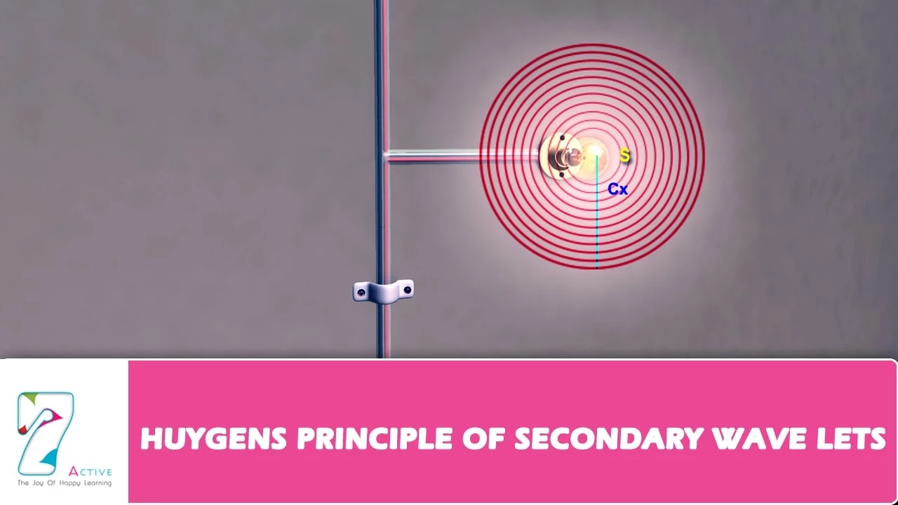
Huygens Principle of Secondary Wavelets
155.6K
According to Huygens' principle, each point on a wavefront acts as a source of secondary wavelets that spread out in all directions with the velocity of light in the medium, and the new wavefront at any later time is obtained by taking the forward envelope of these secondary wavelets; this explains how wavefronts propagate through homogeneous isotropic media, where a spherical wavefront advances as a spherical wavefront and a plane wavefront advances as a plane wavefront, with the amplitude of particles on a backward wavefront being zero due to wave superposition and interference.
Click to watch →

Class 12 Physics Important Derivations | Part 2 Physics 10 Imp Derivation | 12th Physics By RWA
186.7K
This segment introduces Huygens' principle for explaining wave propagation. The instructor explains that every point on a wavefront acts as a source of secondary spherical wavelets. These secondary wavelets spread out in all directions with the same speed as the original wave. The new wavefront is the envelope of these secondary wavelets. The instructor applies this principle to explain reflection of light from a surface. When light reflects, the incident wavefront and reflected wavefront are symmetric with respect to the surface. The angle of incidence equals the angle of reflection, which is the law of reflection.
Click to watch →

Wave Optics in One Shot | Fast Track NEET 2024 | Anupam Upadhyay
33.8K
Huygens' principle states that every point on a wavefront acts as a source of secondary spherical wavelets that propagate forward with the speed of light. The new wavefront is formed by the envelope (tangent surface) of these secondary wavelets. This principle explains how waves propagate through space and can be used to predict the behavior of light when it encounters obstacles or passes through different media.
Click to watch →
तरंग प्रकाशिकी (Wave Optics)One shot Class 12 Physics Chapter 10|UP & Bihar Board Exam
119
Huygens' wave theory, proposed in 1678 by Christiaan Huygens, states that light travels as waves through a medium called ether. The theory proposes that light waves propagate from a source in all directions at the speed of light. Ether is a universal medium with negligible density that allows light waves to travel through it. Huygens' secondary wavelets principle states that: (1) Light travels as wavelets through a medium called ether, (2) Points on a wavefront that vibrate in the same phase are called points of a wavefront, (3) Each point on a wavefront acts as a source of new secondary wavelets, (4) These secondary wavelets propagate in all directions at the speed of light, (5) The new wavefront is the tangent surface to all secondary wavelets at a given instant.
Click to watch →

PNST 2026 | PHYSICS (WAVE OPTICS)| BSc Nursing 2026 | AIIMS ALL State Nursing Exams | RUHS2026 #pnst
13.4K
Huygens' principle states that every point on a wavefront acts as a source of secondary spherical wavelets that spread out in all directions with the speed of light. The new wavefront at any later time is given by the forward envelope (tangent surface) of these secondary wavelets. This principle explains how wavefronts propagate and can be used to derive laws of reflection and refraction.
Click to watch →
Deep Dive
The Principle of Superposition of waves, including how waves combine constructively and destructively.

11 | Waves & Acoustics 08 | Superposition of Waves | Interference | Constructive | Destructive
9.5K
The principle of superposition states that when two or more waves meet at a point in a medium, the net displacement of the particle at that point is equal to the vector sum of the individual displacements produced by each wave. For example, if wave 1 wants to displace a particle by 2 meters upward and wave 2 wants to displace it by 5 meters upward, the net displacement will be 7 meters upward. If wave 1 displaces by 2 meters upward and wave 2 by 5 meters downward, the net displacement will be 3 meters downward. The waves pass through each other without disturbing each other.
Click to watch →
Superposition of waves class 12th physics part 3
50.9K
The Principle of Superposition states that when two or more waves superpose at a common point, the displacement of the particle is equal to the vector sum of the displacements caused by each individual wave. Constructive interference occurs when waves are in phase (phase difference = 0), resulting in maximum amplitude equal to the sum of individual amplitudes (A1 + A2). Destructive interference occurs when waves are out of phase (phase difference = 180°), resulting in minimum amplitude equal to the difference between individual amplitudes (|A1 - A2|). If amplitudes are equal, destructive interference produces zero amplitude.
Click to watch →
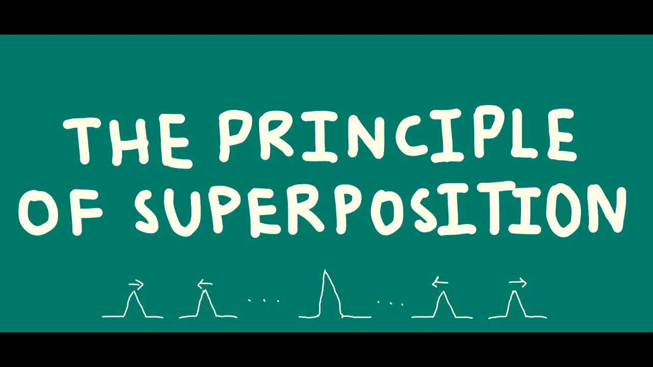
Principle of Superposition | A-level Physics
7.9K
The principle of superposition states that when two or more waves meet, the total displacement at any point is equal to the vector sum of the individual displacements of the waves at that point; this means waves can either reinforce each other (constructive interference when crests meet crests or troughs meet troughs, producing larger displacements) or cancel each other out (destructive interference when crests meet troughs, producing zero displacement), and this principle applies universally to all types of waves including transverse, longitudinal, electromagnetic, and quantum waves.
Click to watch →

Principle of Superposition of Waves | Superposition of Waves | Class 12 | Maharashtra Board
6.3K
The Principle of Superposition states that when two or more waves travel through a medium and meet at a point, the resultant displacement equals the algebraic sum of individual displacements. Constructive interference occurs when waves are in phase (crests align with crests), producing maximum amplitude equal to the sum of individual amplitudes. This fundamental principle explains how waves combine when they overlap in a medium.
Click to watch →
Class 12th – Principle of Superposition | Wave Optics | Tutorials Point
133.5K
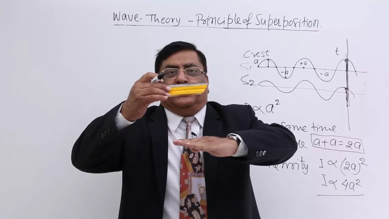
The Principle of Superposition states that when two or more waves meet at a point, the resultant displacement is the vector sum of the individual displacements; when crests of two waves arrive simultaneously, they produce constructive superposition with doubled amplitude and four times the intensity (I ∝ a²), while when a crest meets a trough simultaneously, they produce destructive superposition with zero resultant amplitude and no intensity.
Click to watch →
Deep Dive
The concept of coherent and incoherent sources of light, and the definition of phase and path difference.

الفصل الخامس - البصريات الفيزيائية - المحاضرة 3 - منهج 2026
46.9K
The two slits in Young's experiment act as coherent sources because they emit light waves with a constant phase difference. Coherent sources are wave sources that emit waves with the same frequency, amplitude, and a constant phase difference. The type of interference depends on the path difference between the two waves. If the path difference is zero or an integer multiple of the wavelength (0, λ, 2λ, 3λ...), constructive interference occurs, producing bright fringes. If the path difference is an odd multiple of half the wavelength (λ/2, 3λ/2, 5λ/2...), destructive interference occurs, producing dark fringes. The path difference determines the type of interference at any point on the screen.
Click to watch →

BCS12th-#138 NCERT प्रकाश का व्यतिकरण | INTERFERENCE OF LIGHT |
51.7K
Phase difference is the angular separation between two waves at a given point, measured in radians or degrees. It determines whether constructive or destructive interference occurs. Coherent sources are light sources that emit waves with a constant phase relationship over time, meaning the phase difference between waves from these sources remains unchanged regardless of time. This constant phase relationship is crucial for producing stable and observable interference patterns. The phase difference can be expressed in terms of path difference as φ = (2π/λ)Δx, where λ is the wavelength and Δx is the path difference between the waves.
Click to watch →

CBSE 2024 PHYSICS | Complete Wave Optics in one shot | Class 12 Physics | Sachin sir
258.8K
Coherent sources produce waves with constant phase difference; incoherent sources have continuously changing phase difference. For interference, sources must be coherent. Phase difference Δφ = (2π/λ) × Δx. Constructive interference occurs when path difference is nλ; destructive when path difference is (n + 1/2)λ. When two waves with phase difference φ meet, resultant intensity is I = 4I₀ cos²(φ/2). For constructive interference, φ = 2nπ, giving I = 4I₀ (maximum). For destructive interference, φ = (2n + 1)π, giving I = 0 (minimum).
Click to watch →

Wave Optics in ONE SHOT | Class 12 Physics Chapter 10 | NCERT + CUET | Rakshak Sir
622K
Coherent sources are those that emit waves with a constant phase difference and identical frequency. Incoherent sources have randomly changing phase differences. Coherent sources are essential for interference phenomena. Two independent sources (like two bulbs) are incoherent because their phases change randomly relative to each other.
Click to watch →

فيزياء السادس العلمي المنهج الجديد 2025 | الفصل الخامس | المحاضرة (1) | تداخل الموجات الضوئية
120K
Light interference is defined as the phenomenon of redistribution of light energy resulting from the superposition of two or more light waves. For interference to occur, waves must be coherent (maintaining constant phase relationship), have the same frequency, approximately the same amplitude, travel in the same medium, and arrive at the same point simultaneously. Coherent sources emit waves with constant phase difference, ensuring stable interference patterns. Non-coherent sources produce rapidly changing patterns that cannot be observed due to the persistence of vision, which integrates light over a short period, making rapidly changing patterns appear as continuous illumination.
Click to watch →
Deep Dive
Basic wave parameters such as wavelength, frequency, amplitude, and the wave speed equation.

🔥Applied Physics -2nd || One-Shot || बस इतना कर लो || 2nd Semester || All Branch || By-Anurag Sir
76K
Five fundamental parameters describe wave motion: (1) Amplitude is the maximum displacement from equilibrium position, indicating wave intensity, (2) Time period is the time for one complete oscillation, (3) Frequency is the number of oscillations per second (reciprocal of time period), (4) Wavelength is the distance traveled during one complete oscillation, (5) Wave speed is the distance traveled per unit time. These parameters are related by the fundamental equation v = fλ, where wave speed equals frequency multiplied by wavelength.
Click to watch →
WAVES - INTEGRATED SCIENCE GRADE 9 / PHYSICS FORM 2
1K
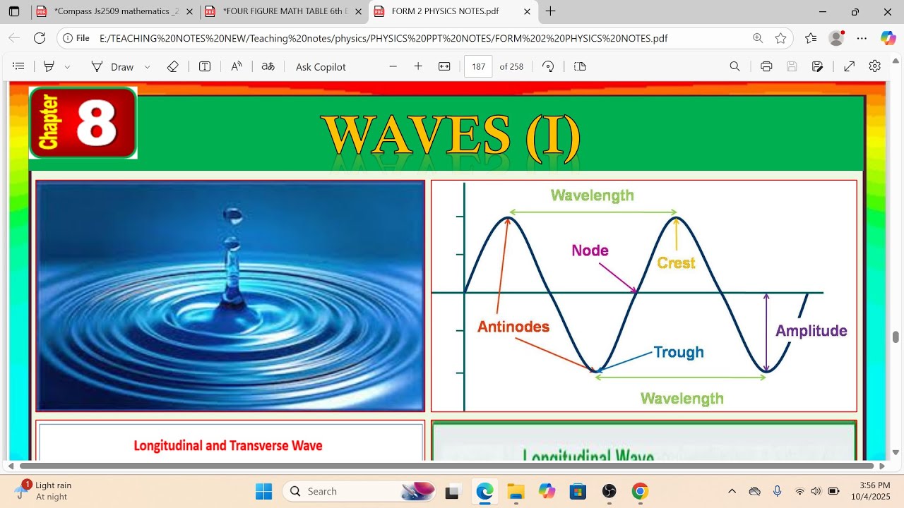
Amplitude is the maximum displacement from the mean position, measured in meters. Frequency is oscillations per second (hertz), while period is time per oscillation (seconds)—they are inversely related: f = 1/T and T = 1/f. Wavelength is the distance between in-phase points on a wave—between successive crests/troughs for transverse waves, or between consecutive compressions/rarefactions for longitudinal waves. The wave equation v = λf relates speed, wavelength, and frequency. Since speed equals distance over time, and one cycle covers one wavelength in one period, substituting T = 1/f gives v = λf. In a given medium, wave speed remains constant, so frequency and wavelength are inversely related—higher frequency means shorter wavelength.
Click to watch →

حل النماذج الاسترشادية فيزياء تانيه ثانوي الترم التاني٢٠٢٦ ليله الامتحان كل سوال بتفصيل|متبقاش جهاز
67K
Wave speed is given by v = fλ. Amplitude is independent of wave speed and frequency. Given speed and frequency, wavelength is λ = v/f. Given speed and amplitude, the amplitude cannot be determined from wave speed alone.
Click to watch →
phys2A ch16.2 Periodic Waves
726
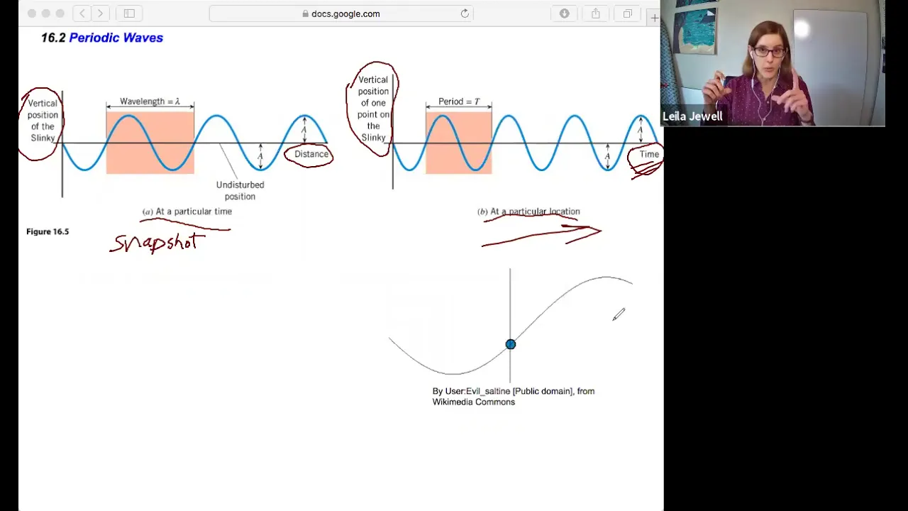
Amplitude (a) is the maximum distance a particle moves from equilibrium. Wavelength (λ) is the horizontal length of one complete cycle, measured in distance. Period (T) is the time for one complete cycle. Frequency (f) is the reciprocal of period (f = 1/T), measured in hertz. The fundamental wave speed equation v = fλ connects these parameters: speed equals frequency times wavelength. This relationship allows calculation of any parameter when two are known, and explains why higher frequency waves have shorter wavelengths when speed is constant.
Click to watch →

Wave Motion 01 | Equation of a wave l Particle Speed & Acceleration I Class11/NEET | RAFTAAR
58.5K
Key wave parameters include wavelength (distance between consecutive compressions or rarefactions), frequency (number of oscillations per unit time), and wave speed. The fundamental relationship is: Speed = Wavelength × Frequency. Angular frequency (ω) is related to frequency by ω = 2πf. These parameters completely describe the characteristics of any wave motion.
Click to watch →
Prerequisite Knowledge
- Concept 01The wave nature of light and Huygens' Principle of secondary wavelets.
- Concept 02The Principle of Superposition of waves, including how waves combine constructively and destructively.
- Concept 03The concept of coherent and incoherent sources of light, and the definition of phase and path difference.
- Concept 04Basic wave parameters such as wavelength, frequency, amplitude, and the wave speed equation.
Subsequent Learning
- Step 01The mathematical derivation of fringe width expression and the intensity distribution curve in interference.
- Step 02Analyzing the effects of medium changes, such as immersing the entire YDSE apparatus in a liquid or introducing a thin mica sheet.
- Step 03Diffraction of light through a single slit and distinguishing it clearly from interference patterns.
- Step 04The concept of resolving power of optical instruments (telescopes and microscopes) based on diffraction limits.
- Step 05Polarization of light waves, confirming the transverse nature of light, and laws like Brewster's Law and Malus's Law.
Intensity Sum
Path Differences
Equal Paths
Fringe Width
Maxima Position
First Maxima
Fringe Shift
Core Solutions
Intensity Sum
2:04Playing Section
- 1
Derives sum of maximum and minimum intensity in interference.
- 2
Explains key wave optics intensity relationships.
- 3
Focuses on core YDSE intensity calculations.
Quantum Wave-Particle Duality and the Measurement Problem
While Young’s Double Slit Experiment is classically taught to prove the wave nature of light, modern quantum physics introduces a critical counterpoint: wave-particle duality. Under classical wave optics, light is viewed as a continuous wave. However, quantum mechanics reveals that light also consists of discrete particles called photons. When the experiment is conducted by firing single photons one at a time, an interference pattern still builds up, suggesting each photon interferes with itself. Crucially, if detectors are placed at the slits to observe which path the photon takes, the interference pattern collapses, and light behaves purely as classical particles. This 'measurement problem' demonstrates that light cannot be fully explained by classical wave equations alone. It introduces students to the Copenhagen interpretation and alternative theories like the De Broglie-Bohm pilot-wave theory, which attempts to explain these quantum phenomena by proposing that physical particles are guided by real, pilot waves.
Deep Dive
The mathematical derivation of fringe width expression and the intensity distribution curve in interference.

WAVE OPTICS ONE SHOT CLASS 12 PHYSICS 🔥 FOR EXAM 2024-2025 || WAVE OPTICS BY MUNIL SIR ||PHYSICS 12
152.6K
The fringe width β = λD/d shows that fringe width is directly proportional to wavelength and distance to screen, and inversely proportional to slit separation. The intensity distribution is I = I₀cos²(φ/2), where I₀ is maximum intensity and φ is phase difference. For two sources with intensities I₁ and I₂, I_max = (√I₁ + √I₂)² and I_min = (√I₁ - √I₂)². The ratio I_max/I_min = (√I₁ + √I₂)²/(√I₁ - √I₂)².
Click to watch →

Wave Optics Chapter - 10 Rapid One Shot Revision Class 12th Physics Full Chapter in 45 Minutes
62.7K
This section covers the mathematical details of interference patterns. The fringe width (distance between consecutive bright or dark fringes) is β = λD/d, where λ is wavelength, D is screen distance, and d is slit separation. The central fringe width is twice the secondary fringe width. Position of bright fringes: xn = nλD/d (n = 0, 1, 2...). Position of dark fringes: xn = (2n-1)λD/2d (n = 1, 2, 3...). The first bright fringe is at λD/d, first dark fringe at λD/2d, second bright fringe at 2λD/d, and so on. In an interference pattern, maximum intensity is 4I0 (where I0 is intensity of each individual wave), and minimum intensity is zero. The intensity distribution follows a sinusoidal pattern. The intensity at any point is given by I = I1 + I2 + 2√(I1I2)cos(φ).
Click to watch →
37.Chapter - 10 | Wave Optics | Young's Double Slit Experience | Physics Baba 2.O
99.8K
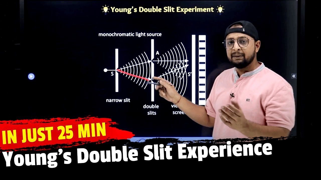
Using the Pythagorean theorem on two right triangles formed by the slits and a point on the screen, the path difference (Δ) is derived as: Δ = √(D² + (d/2 + y)²) - √(D² + (d/2 - y)²). When D >> d (distance to screen much larger than slit separation), this simplifies to Δ ≈ dy/D. The position of bright fringes from the central maximum is y = nλD/d (n = 0, 1, 2...). The position of dark fringes is y = (2n+1)λD/(2d) (n = 0, 1, 2...). The fringe width (distance between consecutive bright or dark fringes) is β = λD/d. The intensity pattern shows a central bright fringe, followed by alternating dark and bright fringes on both sides. All bright fringes have equal intensity, and all dark fringes have zero intensity. The pattern is symmetric about the central maximum.
Click to watch →

Derivation of Expression of Fringe Width in YDSE interference | STD 12 Physics | Wave Optics
120K
In Young's Double Slit Experiment, the fringe width (β) is derived by subtracting the path difference equations for consecutive bright fringes: for the nth bright fringe, y_n × d/D = nλ, and for the (n+1)th bright fringe, y_{n+1} × d/D = (n+1)λ. Subtracting these gives y_{n+1} - y_n = Dλ/d, which represents the distance between two consecutive bright fringes. This same distance applies to consecutive dark fringes as well. The fringe width depends on three factors: it increases when the distance between slits and screen (D) increases, when the wavelength of light (λ) increases, or when the distance between slits (d) decreases. Conversely, if the entire setup is immersed in a liquid with refractive index μ, the wavelength decreases to λ/μ, thereby decreasing the fringe width.
Click to watch →

Complete Physics ( 4 Marks Questions ) Class 12th Maharashtra Boards | Detailed Revision #nie
61.7K
The fringe width (distance between consecutive bright or dark fringes) is derived using geometry and path difference conditions. The formula is w = λD/d, where λ is wavelength, D is screen distance, and d is slit separation. This formula applies to both bright and dark fringes and is fundamental to understanding interference patterns.
Click to watch →
Deep Dive
Analyzing the effects of medium changes, such as immersing the entire YDSE apparatus in a liquid or introducing a thin mica sheet.

RAY OPTICS AND OPTICAL INSTRUMENTS,WAVE OPTICS in Oneshot | Most Expected Questions
802
When the entire YDSE apparatus is immersed in a medium of refractive index μ, the wavelength becomes λ' = λ/μ. The fringe width becomes β' = λ'D/d = (λ/μ)D/d = β/μ. Thus, the fringe width decreases when the apparatus is immersed in a denser medium. The angular fringe width becomes Δθ' = λ'/d = (λ/μ)/d = Δθ/μ.
Click to watch →

Minimum thickness of a mica sheet having \( \mu=\frac{3}{2} \) which should be placed in front o...
243
In Young's Double Slit Experiment, placing a mica sheet with refractive index μ = 3/2 in front of one slit creates a path difference of (μ - 1)t. To reduce the intensity at the screen's center to half the maximum, the phase difference must be π/2, corresponding to a path difference of λ/4. Solving (μ - 1)t = λ/4 gives t = λ/[(μ - 1) × 4] = λ/[(1/2) × 4] = λ/2.
Click to watch →

Interference: Young's Double-Slit Experiment | Physics | JEE 2026 | Siva Sir
2.6K
This section addresses the effect of immersing the entire Young's double slit apparatus in a liquid of refractive index μ. When light enters a medium, the frequency remains unchanged (determined by the source), but the velocity and wavelength change. The wavelength in the medium is: λ_medium = λ_air/μ. The fringe width in the medium becomes: β_medium = (λ_air/μ) × (d/D). The wavelength decreases by a factor of μ, so the fringe width also decreases by the same factor. A numerical example is provided: λ = 690 nm, d = 1.5 mm, D = 0.72 m, μ = 1.44, giving β = 0.23 mm.
Click to watch →

CUET 2026 Physics | Wave Optics Chapter 10 in One Shot | CUET Physics Free Series
5.7K
When YDSE is immersed in a medium of refractive index μ, the wavelength becomes λ' = λ/μ. The angular fringe width becomes θ' = θ/μ. If the separation between coherent sources is halved (d' = d/2) and screen distance is doubled (D' = 2D), the fringe width becomes β' = 4β. The intensity at path difference Δx = λ is I = 4I₀. If this intensity is given as K, then I₀ = K/4.
Click to watch →
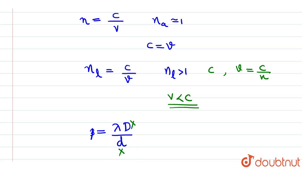
Assertion (A) : If the whole apparatus of YDSE is immersed in a liquid, then the fring
267
When the entire Young's Double Slit Experiment (YDSE) apparatus is immersed in a liquid, the fringe width decreases because the wavelength of light in the liquid is less than in air, as the refractive index of the liquid is greater than 1, which reduces the wavelength according to the relationship λ = λ₀/n, where λ₀ is the wavelength in vacuum and n is the refractive index of the medium.
Click to watch →
Deep Dive
Diffraction of light through a single slit and distinguishing it clearly from interference patterns.

79) Dalga Mekaniği - Tek Yarıkta Kırınım ve Etki Eden Diğer Değişkenler
47.9K
To determine whether an interference pattern is from single slit diffraction or double slit interference, observe the following: (1) In single slit diffraction, the central bright fringe is wider than secondary fringes, and brightness decreases progressively away from center. (2) In double slit interference, all fringes are equal in width, and brightness remains relatively uniform. The number of fringes alone does not indicate which type of pattern it is.
Click to watch →

Diffraction (Young's Double Slit & Grating) - A-level & GCSE Physics
387.2K
Single slit diffraction produces a different interference pattern compared to double slits. The single slit pattern has a very intense central maximum that is double the width of the secondary maxima. The central bright fringe is much brighter and wider than the other fringes. In contrast, double slit interference produces equally spaced bright fringes with gradually decreasing intensity. Both patterns involve diffraction, but the single slit pattern is dominated by the diffraction effect from a single aperture, while the double slit combines both diffraction and interference effects.
Click to watch →

wave optics one shot ncert class 12 | physics ncert class 12 | lec -02 | NEET JEE CBSE
3K
Diffraction is the bending of light around obstacles or through narrow openings. It produces alternating bright and dark regions similar to interference patterns. The central maximum is brightest, with intensity decreasing progressively outward. Single slit diffraction minima occur at a sinθ = nλ (n = ±1, ±2...). Secondary maxima occur approximately at a sinθ = (n + 1/2)λ. The pattern results from superposition of waves from different parts of the slit. The distinction between interference and diffraction is not absolute - Young's double slit pattern can be viewed as superposition of diffraction patterns from each slit.
Click to watch →
Wave Optics-9
1K
When light passes through a narrow slit, it creates a diffraction pattern on a screen with alternating bright and dark fringes. Key characteristics distinguish this from interference: (1) The central bright fringe is the widest and brightest; (2) Subsequent bright fringes decrease in width and brightness progressively; (3) Dark fringes are equally spaced but not equally bright; (4) Fringe width decreases as you move away from the center. These features arise because each point on the slit acts as a secondary source according to Huygens' principle.
Click to watch →

Lec 21: Diffraction, Gratings, Pin Holes, Angular Resolution
920
Single-slit diffraction is fundamentally the same phenomenon as interference but is distinguished by convention. When light passes through a single slit, each point in the aperture acts as a Huygens source, and the resulting interference creates a broad central maximum with alternating bright and dark regions. The distinction between 'diffraction' and 'interference' is largely historical and semantic—both describe wave superposition. The key difference is that single-slit diffraction involves a continuous distribution of sources rather than discrete ones.
Click to watch →
Deep Dive
The concept of resolving power of optical instruments (telescopes and microscopes) based on diffraction limits.

WAVE OPTICS | NEET Physics Crash Course | NCERT Class 12 Physics
73K
Single-slit diffraction creates central maxima with secondary maxima of decreasing intensity. The first minimum occurs at a × sin(θ) = λ. Resolving power determines ability to distinguish close objects: d = 1.22λ/(NA) for microscopes and d = 1.22λ/D for telescopes. These principles explain optical instrument limitations and diffraction-limited imaging.
Click to watch →

Resolving Power of Microscope and Telescope I Wave Optics Class 12th Physics
35.7K
The resolving power of an optical instrument is its ability to distinguish between two closely spaced point objects, determined by the Rayleigh criterion where two objects are just resolved when the central maximum of one diffraction pattern coincides with the first minimum of the other, given by the formula θ = 1.22λ/(a sinθ), where λ is the wavelength of light, a is the aperture size, and θ is the angle of observation; this principle applies to both microscopes and telescopes, with the resolving power being inversely proportional to the limit of resolution.
Click to watch →
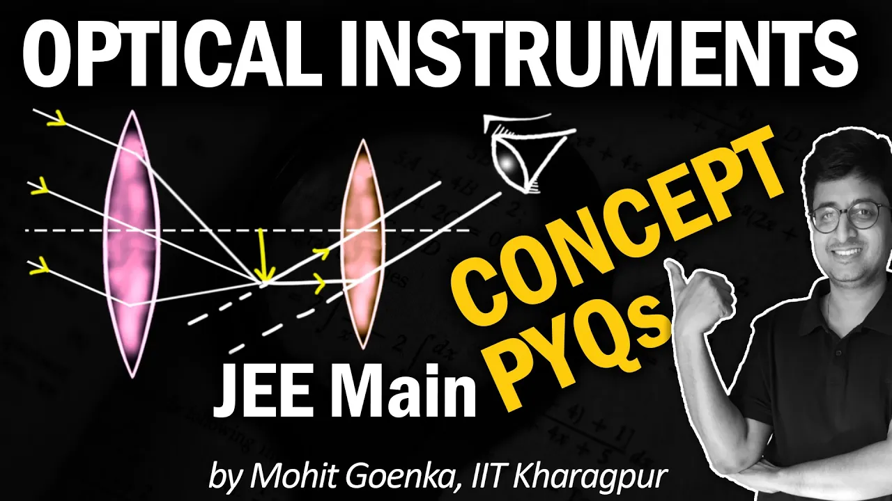
Optical Instruments | REVISION in 20 min | Microscope & Telescope | Resolving Power | JEE Physics
556.5K
The limit of resolution is the minimum angular separation between two point sources that can be distinguished as separate entities. According to Rayleigh's criterion, two points are just resolvable when the central maximum of one diffraction pattern coincides with the first minimum of the other. The minimum angle θ_min = 1.22λ/D, where λ is the wavelength of light and D is the aperture diameter. Resolving power is inversely related to this limit. For telescopes, resolving power increases with larger aperture and decreases with longer wavelength. For microscopes, resolving power also depends on numerical aperture (NA = n sin β).
Click to watch →
Wave Optics Class 11 | NCERT Essentials | NEET 2021 Preparation | NEET Physics | Vinay Sir
43.2K
This segment covers resolving power and the diffraction limit of optical instruments. The instructor explains that the resolving power of an optical instrument is given by the formula R = 1/(θ_min), where θ_min is the minimum angular separation that can be resolved. For a circular aperture, θ_min = 1.22λ/D, where λ is the wavelength and D is the diameter of the aperture. The segment also covers the diffraction limit, explaining that all optical instruments are limited by diffraction, which prevents them from achieving infinite resolution. This limit is determined by the wavelength of light and the size of the aperture. The instructor emphasizes that these concepts are fundamental to understanding wave optics and are essential for students to grasp.
Click to watch →

Wave Optics Class 12 Physics | NCERT Full Chapter for NEET
334.2K
This section examines how diffraction limits the performance of optical instruments. For circular apertures, the Airy disk contains 85% of light energy, with the first dark ring at sin(θ) = 1.22λ/a. Rayleigh criterion states two images are just resolved when the first minimum of one pattern coincides with the center of another. Lens diameter affects resolving power: larger apertures decrease the radius of the first dark ring, increasing resolving power. For telescopes, larger objective diameters improve resolution of distant objects. For microscopes, the minimum separation between two objects is dM = 1.22λ/(2n sinβ), where n is refractive index and β is half the angle subtended by the lens. The quantity n sinβ is the numerical aperture. Higher numerical aperture improves resolving power. This diffraction-limited resolution explains why optical instruments cannot achieve perfect imaging and why larger apertures are essential for high-resolution observation.
Click to watch →
Deep Dive
Polarization of light waves, confirming the transverse nature of light, and laws like Brewster's Law and Malus's Law.

Class 12 Physics 🔥| Wave Optics Most Important Questions | Wake Up! with Ashu Sir
130.8K
Polarization converts unpolarized light (oscillating in multiple planes) to polarized light (oscillating in one plane). Polaroids are special crystals that achieve this. When unpolarized light of intensity I₀ passes through a polarizer, intensity becomes I₀/2. An analyzer checks polarization. Malus's Law states that intensity after the analyzer is I = I₀cos²θ, where θ is the angle between polarization direction and analyzer axis. This demonstrates the transverse nature of light waves.
Click to watch →

Polarization of Light | Wave Optics L 4 | Class 12 Physics | NEET 2020 | NEET Physics |by Gaurav Sir
89.2K
Polarization of light occurs when light waves oscillate in a single plane rather than in all directions perpendicular to propagation; when unpolarized light passes through a polarizer, only the component oscillating parallel to the polarizer's axis is transmitted, with intensity following Malus's law (I = I₀cos²θ). Brewster's angle (θb) is the angle of incidence at which reflected light becomes completely polarized, satisfying the condition tan(θb) = μ, where μ is the refractive index of the medium.
Click to watch →

WAVE THEORY OF LIGHT QUICK EXPLANATION | PHYSICS CRASHCOURSE | MATRIX SCIENCE ACADEMY | MHTCET 2020
33.4K
Polarization is a transverse wave property—longitudinal waves cannot exhibit it. Unpolarized light vibrates in all directions perpendicular to propagation. Passing through a polarizer restricts vibrations to one plane, producing polarized light with intensity halved. Malus' law describes polarized light passing through a second analyzer: I = I₀/2 × cos²(θ), where θ is the angle between polarizer and analyzer. At 90°, no light passes; at 0°, maximum intensity transmits. This demonstrates light's transverse nature. Two key definitions: plane of vibration contains the electric field vector, while plane of polarization is perpendicular to it. Methods of polarization include transmission through dichroic substances, reflection (Brewster's law), and scattering.
Click to watch →

WAVE OPTICS🔥ONE SHOT || PHYSICS || HSC BOARD 2025 #hsc
34.3K
Polarization restricts light vibrations to one plane. Unpolarized light has electric field vectors vibrating in all directions perpendicular to propagation. When passing through a polarizer, only the component in a particular direction passes through. Malus's Law states transmitted intensity I = I0 cos²(θ), where θ is the angle between polarization direction and transmission axis. At θ = 90°, intensity becomes zero (crossed polarizers). This demonstrates the transverse nature of light and is used in various optical applications.
Click to watch →
CUET Physics 2024: Wave Optics💯 | CUET Important MCQs 2024
33.6K
Polarization proves light is transverse. Brewster's Law states that at the polarizing angle, tan(i_p) = n, where n is the refractive index. At this angle, reflected light is completely polarized, and the reflected and refracted rays are perpendicular (90° angle between them). For air-to-glass with n = 4/3, i_p ≈ 53.1°.
Click to watch →
Intensity Sum
Path Differences
Equal Paths
Fringe Width
Maxima Position
First Maxima
Fringe Shift
Core Solutions
Intensity Sum
2:04- 1
Derives sum of maximum and minimum intensity in interference.
- 2
Explains key wave optics intensity relationships.
- 3
Focuses on core YDSE intensity calculations.
Quantum Wave-Particle Duality and the Measurement Problem
While Young’s Double Slit Experiment is classically taught to prove the wave nature of light, modern quantum physics introduces a critical counterpoint: wave-particle duality. Under classical wave optics, light is viewed as a continuous wave. However, quantum mechanics reveals that light also consists of discrete particles called photons. When the experiment is conducted by firing single photons one at a time, an interference pattern still builds up, suggesting each photon interferes with itself. Crucially, if detectors are placed at the slits to observe which path the photon takes, the interference pattern collapses, and light behaves purely as classical particles. This 'measurement problem' demonstrates that light cannot be fully explained by classical wave equations alone. It introduces students to the Copenhagen interpretation and alternative theories like the De Broglie-Bohm pilot-wave theory, which attempts to explain these quantum phenomena by proposing that physical particles are guided by real, pilot waves.
The wave nature of light and Huygens' Principle of secondary wavelets.
The Principle of Superposition of waves, including how waves combine constructively and destructively.
The concept of coherent and incoherent sources of light, and the definition of phase and path difference.
Basic wave parameters such as wavelength, frequency, amplitude, and the wave speed equation.
The mathematical derivation of fringe width expression and the intensity distribution curve in interference.
Analyzing the effects of medium changes, such as immersing the entire YDSE apparatus in a liquid or introducing a thin mica sheet.
Diffraction of light through a single slit and distinguishing it clearly from interference patterns.
The concept of resolving power of optical instruments (telescopes and microscopes) based on diffraction limits.
Polarization of light waves, confirming the transverse nature of light, and laws like Brewster's Law and Malus's Law.
88.2K views3Klikes52:20@vedantuneetOriginal Release: 2019-11-18
hey everyone how are you all you are watching vid channel and i am gaurav gupta your physics master teacher today we are going to do this awesome topic of ydsc part 2. so in last class we have seen all the basics of ydsc we have seen how the waves interfere us all the conditions we have seen how are you all first of all hello deep hello kushi milker kushiwi hello alisha how are you all hi raghav hi sana great to see you all again in my class very good challenge without any delay one of the most important topics of wave optics that is why dsc i2 pass through a region in the same time in the same direction the sum of the maximum and minimum intensities some sum of maximum and minimum intensity you know sum of maximum minimum intensity [Music] [Music] this is known [Laughter] [Music] lambda 2 lambda 3 n plus 1 [Music] [Music] [Music] lambda 2 lambda 3 lambda so on minimum delta x is equal to lambda by two three lambda by two five lambda by two seven lambda by two and so on and uh conditions in the chat box x1 is equal to x2 exactly is [Laughter] situation is traveled perpendicular divided is y is equal to delta x capital d but divided by small d but it's my condition here [Music] [Music] [Music] correct is [Music] [Music] maximum lambda d by small d [Music] screen foreign for lambda d by d third minimum phi lambda d by two d so on a glass seventh sorry conditions maximum lambda foreign wavelength one by two mmd distance between first maxima and central maxima challenge our answer y by capital is foreign lambda is equal to is [Laughter] [Music] [Music] it is found that ate the bright fringe in the medium lies where fifth dark [Music] foreign okay foreign foreign [Music] [Music] is foreign okay [Music] foreign very good it was nice interacting with all of and then subscribe to the channel share it with your friends and also hit the like button this is gaura gupta signing off milton accession bye bye everyone
Up Next

60:14
Human Eye & Its Defects Class 10 Physics | POLYCET
@TSATNetwork
100 views•2026-04-06

12:53
21cm Hyperfine Transition in Neutral Hydrogen: Radio Astronomy Basics
@AaronRobertParsons
12.4K views•2011-10-13

32:32
NMR Spin Physics I: Zeeman Effect, Resonance Condition & Larmor Frequency
@nptel-indianinstituteofsci8064
2.3K views•2024-01-17

27:14
Entropy and the Second Law of Thermodynamics Explained
@veritasium
27.5M views•2023-07-01
Related Study Plans & Knowledge Roadmaps
Structured learning paths in Physics
physics
Nuclear Physics (Decay, Fission & Reactors)
01Atomic Structure and the Binding Force
02Radioactive Decay and Half-Life
03Nuclear Fission Mechanics and Chain Reactions
+ 2 more learning modules
12h5 modules
Explore Roadmap
physics
Soft Matter (Polymers, Colloids & Rheology)
01Foundations of Soft Matter & Thermal Forces
02Polymer Physics and Macromolecules
03Colloids, Surfactants, and Self-Assembly
+ 2 more learning modules
38h5 modules
Explore Roadmap
physics
Analytical Mechanics: Lagrangian & Hamiltonian
01Mathematical Foundations: Calculus of Variations
02From Newtonian Mechanics to Constraint Dynamics
03The Principle of Least Action & Lagrangian Mechanics
+ 3 more learning modules
28h6 modules
Explore Roadmap
physics
General Relativity (Spacetime & Cosmology)
01Foundations of Relativity: Special Relativity
02The Geometry of Spacetime: Equivalence Principle & Curvature
03Einstein's Field Equations: The Mathematics of Gravity
+ 2 more learning modules
55h5 modules
Explore Roadmap