




![[임베디드 기초 뿌수기 11-7] 타이머/카운터를 이용한 DC모터 제어 실습 이론](https://i.ytimg.com/vi/ZYA0omWKwHo/maxresdefault.jpg)












![Roborace Robot using Arduino and BTS7960 | Wireless Robot with Flysky fsi6 [without Brushed ESC]](https://i.ytimg.com/vi_webp/EnbkdrYQ0NE/maxresdefault.webp)




![DCS World Mission Design with MOOSE - Finite State Machines - 1. Concept [DCS World][Tutorial]](https://i.ytimg.com/vi_webp/S0d0dpyeaWs/maxresdefault.webp)



This tutorial demonstrates how to control a DC motor's speed and direction using a rotary encoder and L9110S motor driver with Arduino. The rotary encoder provides continuous rotation input that is read via interrupt on pin 2, allowing the code to efficiently detect rotation changes without blocking other operations. The encoder's clock pin triggers an interrupt when the rotor position changes, enabling real-time speed and direction control. The motor driver uses PWM signals on pins 10 and 11 to control motor speed, while the direction pin determines rotation direction. A switch integrated in the encoder can reset the motor position to zero. The code maps encoder position values to motor speed, with positions between 0-11 resulting in no movement, 10-20 producing slow forward speed, and 90-100 producing full forward speed.
DC Motor Control with Arduino and L9110S Driver Tutorial
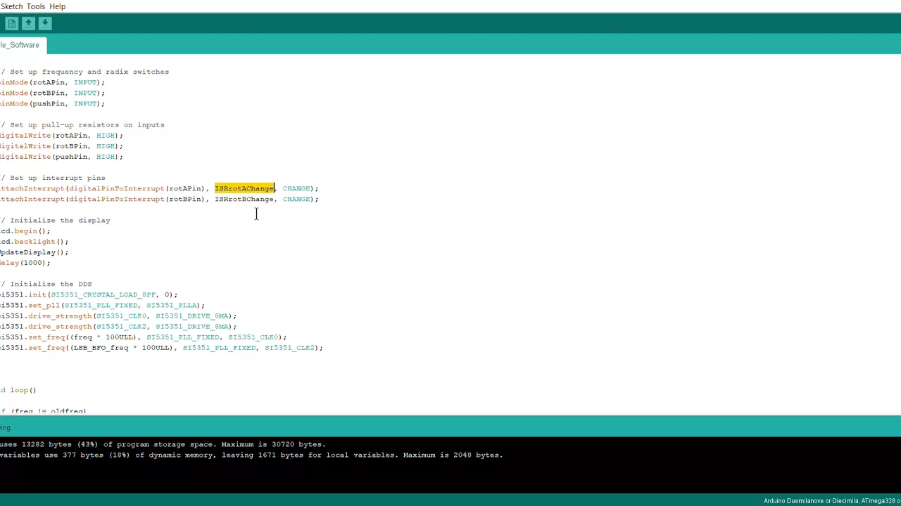
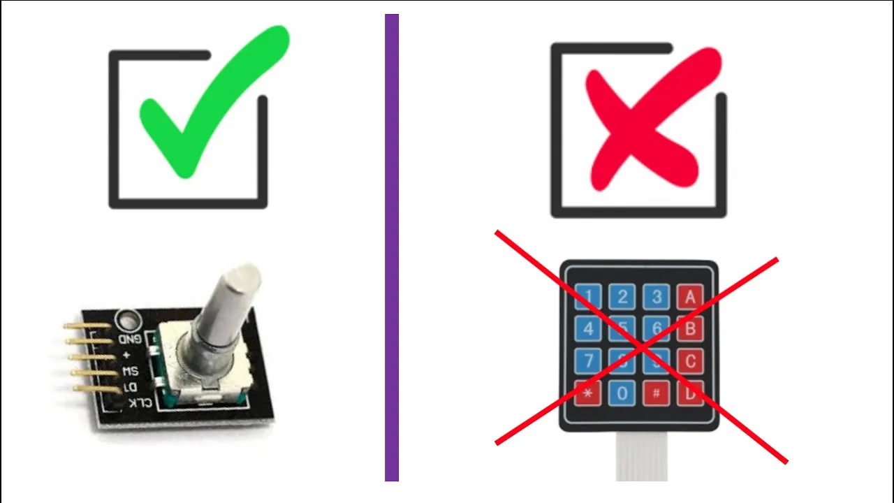
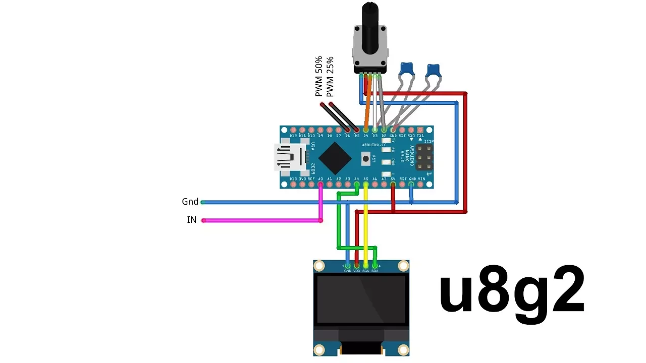
Added:[Music] all right hello again everyone this is Ivan from brainy bits.com uh today I'm going to show you how to control a DC motor using a motor driver this one is the l9110s dual motor driver we're only going to connect one today but you connect another one here on this terminal to to connect another one and the way we're going to control the speed and direction of our motor we're going to use a rotary encoder uh basically a rotary encoder keeps on turning there's no end to it in one way or the other so we're going to control the speed and direction with this and also there's a switch that's integrated in it and we're going to use that to actually put the value at zero meaning stop the motor so we're going to go through the connections and after we're going to go see the code we're going to use an interrupt today to actually read the value of the rotary encoder uh because if we weren't using an interrupt it would be hard for our code to do anything else but look at this to see if anything is changing on the rotary encoder and do anything else so it would be bogged down by looking at this by using an interrupt when this happens when it detects that something is happening on the rotor encoder it will stop the code read the value come back so we'll look at that later uh connections are pretty simple uh on a rotary encoder we have a clock a direction a switch and voltage and ground now our clock is connected to pin number two this one is important that it's connected to number two because this is the one that we're going to use for the interrupt on a Uno we have two available pins for interrupts we have pin number two which uh is interrupt zero and pin number three which is inter interupt one other arduinos have more uh or less well more I guess interrupt pins available but on the Uno we have two uh the other pins number three is connected to our Direction and number four is connected to our switch voltage and ground is connected directly to the Uno because this uses almost no power so that's for the encoder the motor driver we're using a breadboard power supply to supply 5 volts to the breadboard rails uh because we don't want to drive a motor directly from the Uno motor tends to uh draw a lot of current even a small one like this could well maybe not damage but at least reset the uh the Uno so yeah so we're connecting voltage and ground to the breadboard and the other two pins b1a b1b one is for the pulse withd modulation signal and the other one would be for direction of the motor uh pin number 10 and 11 uh as always you can go to our website Briny bits.com you'll find a tutorial there and also you'll find a schematic which will show you all these connections a lot better so you could uh go and check that out later after that our motor is connected to our module uh these you can inverse there's no really polarity here what what will happen basically is the uh motor will drive will spin one way or the other depending on these connections uh one thing to note though uh the motor needs to have a little capacitor like this between its terminal this is to prevent spikes or you know Sparks to actually reset our uino so this is a little one uf capacitor most of the time these come sold uh soldered onto the motor itself if not just add one of those and you'll be fine so this is the connections we need to make we're going to go see the code the code is a little bit long but most of the code what it does is check the value of this to set the speed and direction of this so basically it looks long but it's not that bad and we'll look at the interupt also in our code so let's go take a look at that all right so here we are at the code this is the code we're going to use now like I said it looks long but mostly all this part here whoops all it does is check the rotation of the um it takes the rotation value of the rotary encoder and translates that into a direction and a speed so all this stuff that's all it does so we're going to start at the top here I'm going to Define two variables turn detected and up and we're going to put those volatiles because we're going to use these in the interrupt code so they need to be volatile for interrupts then we do our pins and the connection to the motor driver and then we Define motor B pwm for the pwm speed to that V to that uh connection here and this one to the other connection then this is the interrupt so basically this will run if the CLK pin on the encoder goes from high to low because when you turn a rotary encoder it goes from high to low meaning something has happened so something happens it's going to run this little bit of code here at the beginning we put a delay of four that's for debouncing the rotary encoder so we don't skip or repeat steps then we do a digital read if it goes clockwise then we set up to that value else it's going counterclockwise so we do the KN to actually put the other the opposite value and then we put turn detected to true meaning a turn has occurred on the rotary encoder then we're at our setup so we set our inputs and then we put the the S SW which is a switch to high to pull to enable the pull up resistor for the switch then we attach attached the interrupt zero because we're using pin two uh the ISR and falling meaning going from high to low pin for the motors at output and we put them both too low to set the motor to off at the beginning then we're going to do the loop our main Loop so static long rotary position equals zero that will be the value of the rotary encoder we set it to zero so at the beginning it starts at zero it's a static so it counts uh correctly the steps now we do we check if the button is pressed if it is and the rotary position is already equals zero then we don't want to do this bit of code here if it's already at zero it means we already ran this so we're going to get out if not if it's not at zero we put it at zero and we put both pin of the motor to low to turn the motor off and then we print reset in the serial monitor window and the position also which would be zero now this will run if rotation was detected so if turn detected so in our interrupt up here where is it there it is if there is a turn then we said turn detected equal true so we're going to go here turn detected yes if it's up meaning clockwise we're going to check the position if it's greater or equal to 100 then we're going to set it to 100 because we don't want to go higher than 100 if it's not we increase it value by two so if it's let's say that's 52 it's going to go to 54 else meaning it's going counterclockwise then we check if it's smaller or equal to minus 100 if it is we set it to minus 100 we don't want to go higher than that else it does the same thing and then we do turn detected to false so it waits until a new rotation is detected we are going to print the speed meaning the rotary position that it's at now the rest of the code is basically all it does it takes that rotation position value and sets the motor to a certain speed rotary position is greater than 0 and smaller than 11 meaning between 0 and 11 we don't do anything we don't want to turn the motor at that point if it's greater than 10 and smaller than 21 then we say digital right high that means the direction is forward and a power at pwm of 180 which is fairly low it's it goes opposite the smaller the number the uh faster the speed and when you go in reverse it's the other way around so we do these until we get to 100 right here if the rotary position is greater than than 90 then the value is going to be 20 which is full speed or maximum speed we could go now we do the same thing for the counterclockwise but we're using negative values so if rotary position smaller than zero and greater than -1 then turn power off we don't want to do anything at the beginning same thing for between -1 and -20 but as you can see the values are opposite instead of being 180 for slow now it's 40 so we're going the other way and all the way up to 200 which is full reverse speed so there you go uh you know it's not too complicated you just got to take it one line at a time and it's you know you'll get it it's uh the interrupt is not too hard to understand on this one uh one thing I did notice the delay of four is important for the bouncing and it works fairly well so it's a simple way to do the the bouncing of the rotary encoder so so we're going to compile the code upload it to uh the Uno and check out uh check it in action so let's take a look all right so we're back uh we already uploaded the code to the Uno uh we powered up the breadboard to give power to our module and plugged in the Uno so it's ready to go nothing's happening right now because I haven't uh turn my rotary encoder yet so I'm going to go ahead and go clockwise first and you'll see the Valu changing on the um serial monitor at the same time so here we go there we go our motor starts we're at 12 so once it hits 10 it starts going a little bit faster as we turn all the way to 100 and there we go full speed I can bring it down or I can just press the switch to stop it completely there we go now we're going to go the other way in Reverse same thing as I turn it increases up to 100 and then it stops there going back down and pressing the switch stop so there you go that seems to work pretty good our delay of four that we put uh to debounce the rotor encoder seems to be working pretty good we're not uh jumping too much and not missing any steps so there you go guys that's one way to control the speed of a motor using a rotary encoder and to drive the motor we're using the L 911 0s uh as always uh look at our website you'll find the schematics the code that we use to make your life a little bit easier instead of retyping everything and also uh you know that's one way to do it but go ahead modify the code play around with it that's how you learn uh once again I'm Ian from bits.com and I hope to catch you guys later [Music]
Up Next

Active Omni-Wheel Design and Mechanics for Two-Axis Control
@jamesbruton
2.8M views•2022-02-01

Triumph of Orthodoxy Icon: Byzantine Art & History Explained
@BenCallan
2.1K views•2024-08-06

FastAPI vs Flask vs Django: Choosing the Right Python Web Framework
@TechWithTim
302.5K views•2024-05-26

Game of Thrones Opening Credits: A Cinematic Analysis
@gameofthrones
46.3M views•2011-04-18
Related Study Plans & Knowledge Roadmaps
Structured learning paths in General & Interdisciplinary Studies