A voltage divider is a fundamental electronic circuit consisting of two resistors connected in series between a voltage source and ground, which creates a reference voltage at the node between them; the voltage at this node is determined by the ratio of the resistor values according to the formula Vout = Vin × (R2/(R1+R2)), where for example, with a 5V supply, 10kΩ and 20kΩ resistors, the output voltage is approximately 3.33V.
Voltage Divider Explained: Ohm's Law Tutorial for Electronics
Added:Deep Dive
Understanding of basic electrical quantities: Voltage (V), Current (I), and Resistance (R).

Basic Electrical Quantities (Full Lecture)
22.6K
This lecture introduces four fundamental electrical quantities: voltage (measured in volts, representing the energy differential across two points), current (measured in amperes, representing the flow of charge through a single point), resistance (measured in ohms, representing opposition to current flow), and power (measured in watts, calculated as voltage multiplied by current). Ohm's Law (I = V/R) describes the relationship between these quantities, where current equals voltage divided by resistance. The lecture emphasizes that voltage is a two-point measurement while current is a single-point measurement, and introduces common instrumentation including ohmmeters, voltmeters, and ammeters for measuring these quantities. The instructor uses water flow analogies to illustrate these concepts and explains that conventional current flow (from positive to negative) is the accepted standard despite electrons actually flowing in the opposite direction.
Click to watch →

Network Theory 01 | Basics of Network Theory Part-1 | EE & ECE | GATE 2024
35.4K
The four basic electrical quantities are Charge (Q), Current (I), Voltage (V), and Power (P). These quantities form the foundation of electrical engineering. Charge has two electrical effects: separation of charge (which creates voltage) and flow of charge (which creates current). Without these basic quantities, nothing else in electrical engineering can be understood.
Click to watch →
![CURSO DE ELETRÔNICA GERAL AULAS GRÁTIS [01] Iniciantes e Avançados | ANDRÉ CISP](https://i.ytimg.com/vi/h48cZV9T-X0/maxresdefault.jpg)
CURSO DE ELETRÔNICA GERAL AULAS GRÁTIS [01] Iniciantes e Avançados | ANDRÉ CISP
135
The three fundamental electrical quantities are voltage, resistance, and current. Voltage (V) is the difference in electrical potential between two points in a circuit, measured in volts using a multimeter. Current (I) is the ordered movement of electrons through a conductor, measured in amperes. Resistance (R) is the opposition to current flow, measured in ohms. Current flows from higher potential to lower potential, requiring a voltage difference to flow. Without voltage, electrons move randomly in all directions. Understanding these three quantities is fundamental to circuit analysis.
Click to watch →

Basics of ELECTRICAL ENGINEERING l BEE Basics I BEE l Lecture 2
544
This section covers the three fundamental electrical quantities. Electric charge is a basic property of matter that causes electrical and magnetic phenomena, existing as positive or negative types. Current is the rate of charge flow through a material, measured in Amperes. Voltage (electromotive force) is the work done per unit charge to move charge between two points, measured in Volts. These quantities form the foundation for understanding all electrical phenomena and circuit behavior.
Click to watch →

⚡ “तुमचं basic electrical strong आहे का? Try this quiz 😎”#electrical#wiringworld
149
This segment covers the basic electrical quantities and their SI units: (1) Current - measured in amperes (A), representing the flow of one coulomb of charge per second; (2) Voltage - measured in volts (V), representing the potential difference that drives current; (3) Resistance - measured in ohms (Ω), representing opposition to current flow; (4) Power - measured in watts (W), representing the rate of energy transfer. These fundamental quantities form the basis for understanding all electrical circuits and are essential for solving electrical problems.
Click to watch →
Deep Dive
Familiarity with Ohm's Law (V = I * R) and how to solve for different variables.
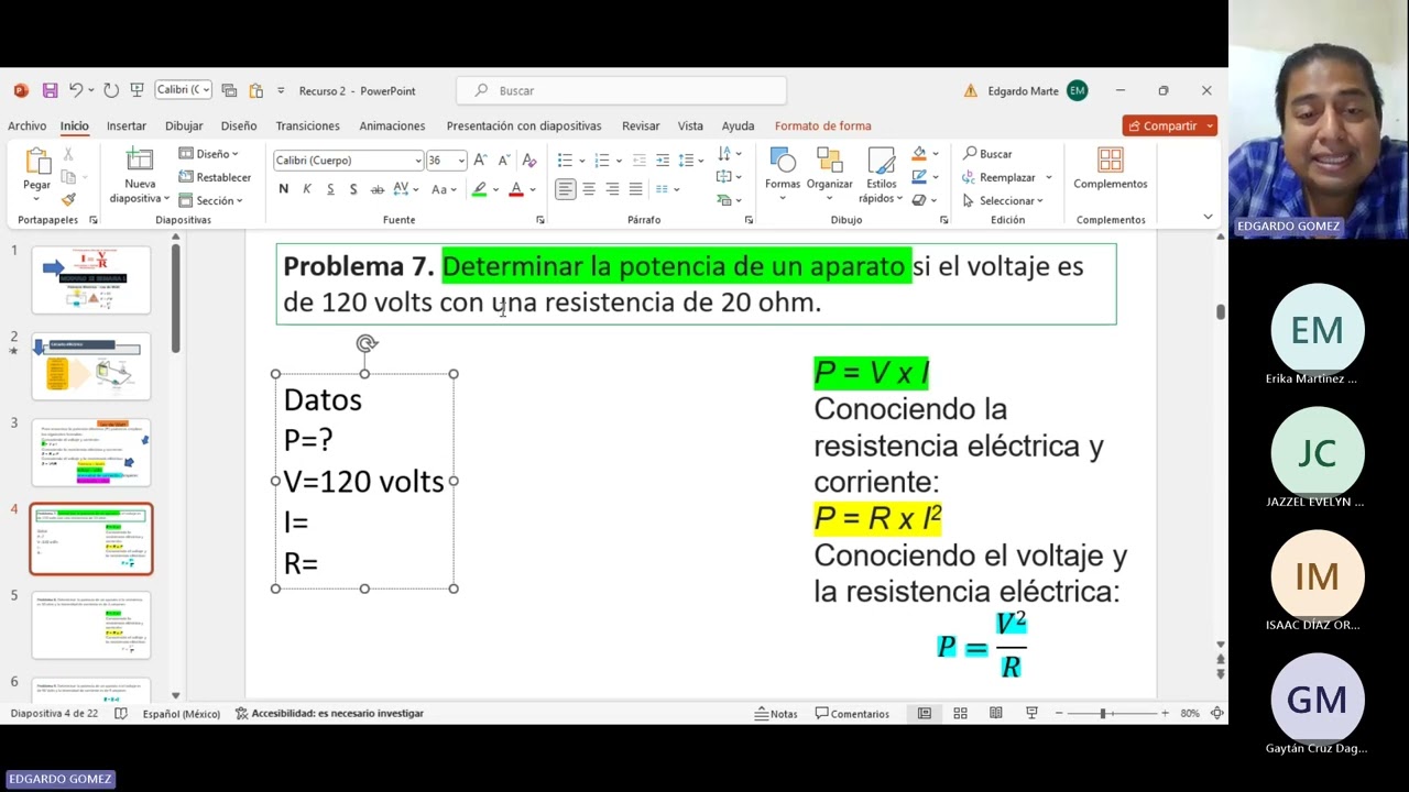
Segunda reunión semana 1 modulo 12 generación 52
115
Ohm's Law can be rearranged to solve for any of the three variables: (1) V = I × R (to find voltage), (2) I = V / R (to find current), and (3) R = V / I (to find resistance). For example, with voltage = 30V and resistance = 10Ω: I = 30 / 10 = 3A. With current = 4A and resistance = 10Ω: V = 4 × 10 = 40V. With voltage = 11V and current = 5A: R = 11 / 5 = 2.2Ω. Always include units in calculations.
Click to watch →

Ley de Ohm ejercicios resueltos
3.8K
Ohm's Law (V = I × R) relates voltage, current, and resistance, and can be rearranged to solve for any variable: I = V/R or R = V/I. When solving problems, convert units to compatible prefixes (e.g., milli/kilo cancel out) to simplify calculations. For example, 12V/4Ω = 3A, 5V/105Ω = 0.05A, and 6V/3kΩ = 0.002A.
Click to watch →

Ohm's Law - Understanding Ohm's Law and V=IR
11.2K
Ohm's Law describes the fundamental relationship between voltage (V), current (I), and resistance (R) in an electrical circuit, expressed as V = I × R, where voltage represents the electrical force driving electrons through a conductor, current measures the rate of electron flow, and resistance opposes this flow; this relationship can be rearranged to solve for any variable (I = V/R or R = V/I), and is commonly applied in circuit calculations such as determining that a 6V battery connected to a 2Ω resistor produces 3A of current.
Click to watch →

CLASS 9 PHYSICS ALL EQUATIONS AND UNITS | Eduport
124.3K
Ohm's Law states that Voltage (V) equals Current (I) multiplied by Resistance (R), expressed as V = IR. This fundamental relationship in electricity can be rearranged to solve for any of the three variables: I = V/R for finding current, and R = V/I for finding resistance. Students should memorize this equation as it is essential for solving electrical circuit problems and understanding the relationship between voltage, current, and resistance.
Click to watch →
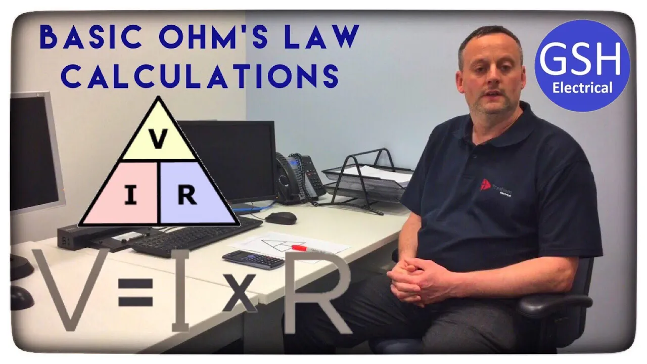
Basic Ohm's Law Calculations V = I x R With Examples and Questions
77K
Ohm's Law states that voltage (V) equals current (I) multiplied by resistance (R), expressed as V = I × R; this relationship can be rearranged using a triangle diagram where covering the desired variable reveals the calculation method: voltage equals current times resistance (V = I×R), current equals voltage divided by resistance (I = V/R), and resistance equals voltage divided by current (R = V/I). These fundamental calculations allow determination of any one electrical quantity when the other two are known.
Click to watch →
Deep Dive
Concept of series circuits, specifically how current is constant and resistances add up in a single path.

Associação de Resistores (EM SÉRIE) - Aula 01
961K
In a series circuit, all resistors are connected to the same conductor (same wire). Because there is only one path for the current to flow, the electric current (I) passing through each resistor is identical. The current does not divide or change as it passes through each component; it remains constant throughout the entire circuit. This is a fundamental property of series circuits.
Click to watch →

विद्युत - 2 भौतिकी Hindi Medium -10th / IIT-JEE / NEET by - J.P.Sir
16.3K
In series combination of resistors, the current remains constant throughout the circuit. When resistors are connected end-to-end in a single path, the same current flows through each resistor. The total resistance is calculated by adding all individual resistances: R_total = R1 + R2 + R3 + ... + Rn. This is the fundamental principle of series circuits where the current has only one path to flow through.
Click to watch →

Resistors in Series I Circuits I Conceptual Physics
598
Resistors connected end-to-end are said to be in series. In a series circuit, the current is the same throughout the entire closed loop because there is only one pathway for the current to travel. The total resistance in a series circuit is calculated by simply adding all individual resistances together (R_total = R1 + R2 + R3 + ...).
Click to watch →

Physics Electric current 12th physics by Akash sir part 4
339
In series circuits, resistors are connected end-to-end in a single path. Total resistance equals the sum of individual resistances (R_total = R1 + R2 + R3). The current remains constant throughout the entire circuit, meaning the same current flows through all components regardless of their resistance values.
Click to watch →
Electricity and MagnetismI Physics I Day 3I Bridge Course
447
In a series combination of resistors, the current is constant and the same current flows through all resistors. This is because there is only one path for the current to flow, so the same amount of charge passes through each component in sequence.
Click to watch →
Deep Dive
Basic algebraic manipulation skills to understand and derive circuit equations.

آموزش صفر تا صد مدار الکتریکی 1 - مدارهای مرتبه دوم - قسمت بیست و یکم
1.9K
This segment covers the fundamental algebraic techniques used to simplify circuit equations before solving them. The instructor demonstrates: (1) dividing terms by coefficients (e.g., dividing by 2), (2) multiplying entire expressions by fractions (e.g., multiplying by 1/2), (3) combining like terms with the same variable (e.g., Vi3 - Vi4), (4) performing arithmetic on constant fractions (e.g., 1/6 + 2/3 = 1/2), (5) moving terms across the equality sign while changing their signs, and (6) eliminating variables by subtracting one equation from another. These techniques are essential for transforming complex circuit equations into simpler forms that can be solved systematically.
Click to watch →
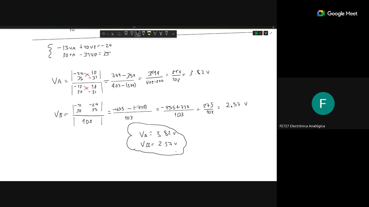
Semana 8, Electrónica Analógica
256
This segment demonstrates the algebraic manipulation required to simplify circuit equations. The instructor shows how to multiply both sides of an equation by the least common multiple of denominators to eliminate fractions. The process involves distributing terms, combining like terms, and rearranging the equation to isolate variables. This algebraic manipulation is essential for preparing equations for solution and is a critical skill in circuit analysis.
Click to watch →

Fundamentos de circuitos eléctricos, Sadiku. Problemas resueltos (3.8-3.9)
1.8K
Circuit equations often require algebraic manipulation to simplify solving. The instructor demonstrates multiplying the entire equation by a common factor (5) to eliminate fractions, then combining like terms (7B1 - 4B0 - 15 = 0). This process transforms complex equations into simpler forms that are easier to solve, a fundamental skill in circuit analysis.
Click to watch →

تمرين عملااااق بأفكار رائعة📚مكثفة ووشيعة ❤️ بكالوريا 🇩🇿
6K
When deriving circuit expressions, algebraic manipulation is essential: (1) Factor common terms, (2) Combine fractions, (3) Use identities like (a+b)(a-b) = a² - b², (4) Substitute known relationships. These skills are crucial for simplifying complex circuit equations.
Click to watch →
Fundamentos de circuitos eléctricos, Sadiku. Problemas resueltos (3.20-3.21)
1.3K
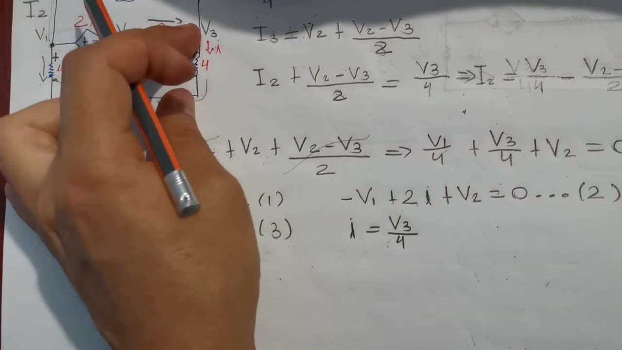
Circuit equations often require algebraic manipulation to simplify and solve. The instructor demonstrates multiplying equations by resistance values (4000Ω) to eliminate denominators, then combining like terms. For example, multiplying by 4000 transforms the equation 3mA = (B1 - B2)/4kΩ + (B1 - B3)/2kΩ into 12 = B1 - B2 + 2(B1 - B3), which simplifies to 3B1 - B2 - 2B3 = 12.
Click to watch →
Prerequisite Knowledge
- Concept 01Understanding of basic electrical quantities: Voltage (V), Current (I), and Resistance (R).
- Concept 02Familiarity with Ohm's Law (V = I * R) and how to solve for different variables.
- Concept 03Concept of series circuits, specifically how current is constant and resistances add up in a single path.
- Concept 04Basic algebraic manipulation skills to understand and derive circuit equations.
Subsequent Learning
- Step 01The 'loading effect' and why resistive voltage dividers are not suitable as power supplies for heavy loads.
- Step 02Practical applications of voltage dividers with analog sensors (e.g., photoresistors/LDRs, thermistors, and potentiometers).
- Step 03Kirchhoff's Voltage Law (KVL) and Kirchhoff's Current Law (KCL) for analyzing more complex circuit networks.
- Step 04Active voltage regulation techniques using Zener diodes and linear voltage regulator ICs (like the LM7805).
- Step 05Using voltage dividers to set reference voltages in Operational Amplifier (Op-Amp) and comparator circuits.
Voltage Divider Basics
Reference Voltage Relation
Formula Application
Example Verification
Voltage Divider Basics
0:00Playing Section
- 1
Core electronic circuit used repeatedly in schematics.
- 2
Standard form uses two resistors in series.
- 3
Connects between a voltage source and ground.
The Loading Effect and Inefficiency of Passive Voltage Dividers
While a passive resistive voltage divider is a fundamental circuit concept, it has severe limitations in practical electronics applications. It cannot maintain a stable voltage when a load is connected to its output; the load's input resistance acts in parallel with the divider's bottom resistor, which alters the total resistance and causes the output voltage to drop (known as the loading effect). Furthermore, resistive dividers are highly inefficient for power delivery because they continuously dissipate power as heat. Consequently, practical electronics design requires active alternatives, such as op-amp voltage buffers to prevent loading, or dedicated voltage regulators (like LDOs and buck converters) for efficient power management.
Deep Dive
The 'loading effect' and why resistive voltage dividers are not suitable as power supplies for heavy loads.
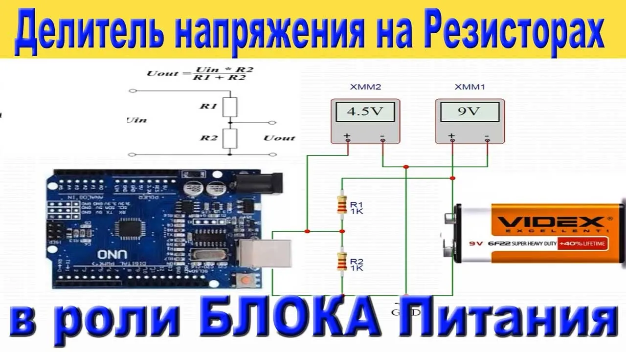
В чем проблема Резистивного ДЕЛИТЕЛЯ и почему его нельзя использовать как Блок ПИТАНИЯ
972
Resistive voltage dividers cannot be used as power supplies because when a load is connected, the load resistance appears in parallel with the lower resistor of the divider, changing the effective resistance and causing the output voltage to drop significantly; this makes them suitable only for very low-current applications like input circuits of measuring instruments, not for powering electronic devices that require stable voltage under varying load conditions.
Click to watch →
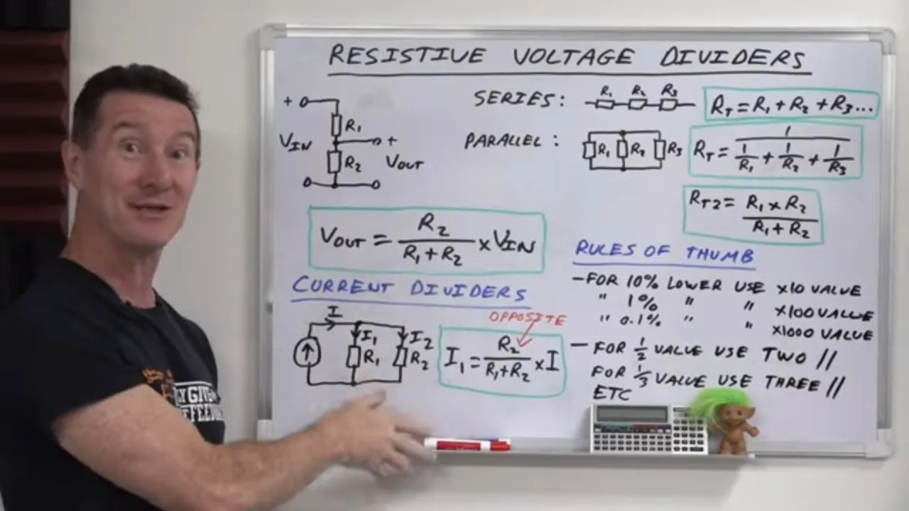
EEVblog 1399 - DC Fundamentals Part 3: Voltage Dividers
84.4K
Voltage dividers function best when driving loads with impedance at least one order of magnitude higher than the Thevenin resistance. For example, with a 5kΩ Thevenin resistance, the load should be 50kΩ or higher. If the load is 50kΩ, error is approximately 10%. If the load is 500kΩ, error drops to about 1%. Higher impedance loads minimize loading effects on the voltage divider.
Click to watch →
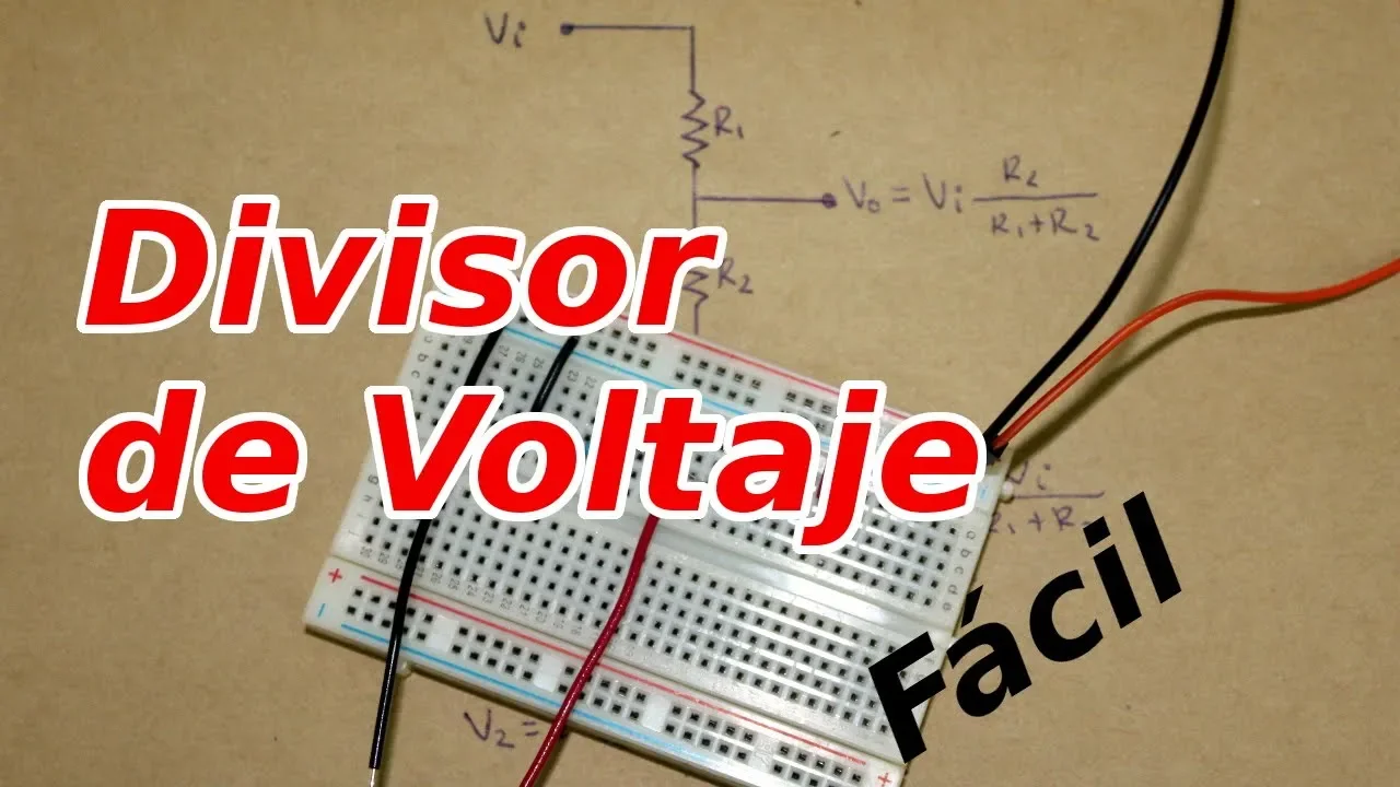
Divisor de Voltaje Resistivo
53.3K
A resistive voltage divider is a simple circuit consisting of two resistors in series that divides an input voltage into a smaller output voltage, calculated using the formula Vout = Vin × (R2 / (R1 + R2)), where the output voltage is proportional to the ratio of the resistances; however, this circuit is only suitable for low-power applications because it dissipates significant power as heat, making it impractical for high-current requirements.
Click to watch →
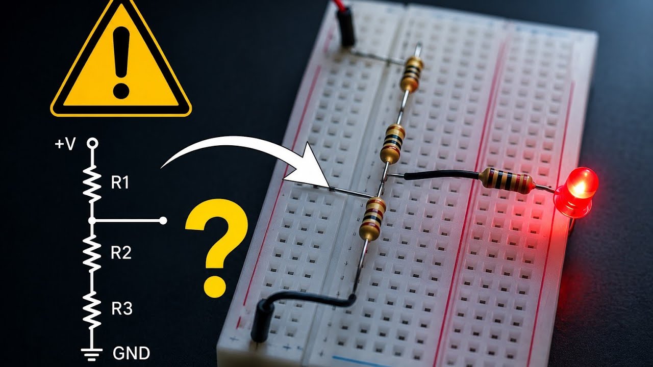
O erro que faz o divisor de tensão falhar
1.4K
A voltage divider circuit works correctly only when it is not connected to a load; when a load is connected, the load draws current in parallel with the resistors, changing the equivalent resistance and causing the output voltage to drop significantly, which is why voltage dividers are ideal for creating reference voltages but not for powering loads.
Click to watch →
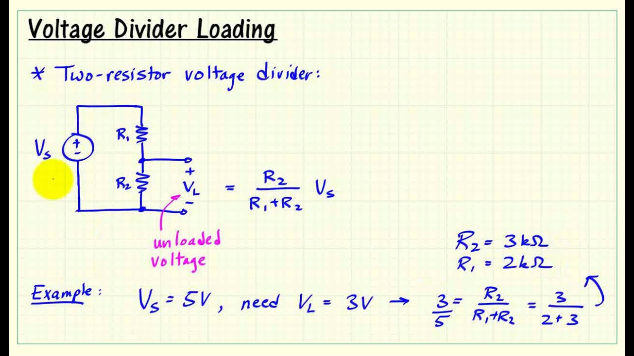
myDAQ mini-lab: Voltage Divider II -- Loading effects -- Whiteboard lecture
28.6K
When a load is connected to a voltage divider, the load resistance forms a parallel combination with the lower resistor (R2), reducing the effective resistance and causing the output voltage to drop below the designed unloaded value; to minimize this loading effect, R2 should be much smaller than the load resistance, though this conflicts with minimizing current draw from the source, requiring a trade-off between resistor values.
Click to watch →
Deep Dive
Practical applications of voltage dividers with analog sensors (e.g., photoresistors/LDRs, thermistors, and potentiometers).

Series & Parallel - Potential Divider Circuits - GCSE & A-level Physics
265.6K
This concluding section demonstrates real-world applications of potential divider circuits with variable resistors. Thermistors change resistance with temperature: cooling increases resistance, increasing voltage share. Connecting a heater in parallel with a thermistor creates automatic temperature control - when cold, higher thermistor voltage activates the heater. Similarly, LDRs change resistance with light intensity. For street lighting, connecting a lamp across the LDR means darkness (higher LDR resistance) increases voltage to turn on the light. These examples show how potential dividers enable sensor-based automatic control systems.
Click to watch →

Tutorial 03 for Arduino: Electrical Engineering Basics
694.4K
A potentiometer (pot) is a variable resistor with a wiper that moves along a resistive track, effectively creating a voltage divider. When connected between 5V and ground, the wiper position determines the output voltage. At the bottom position, the wiper connects to ground (0V); at the top, it connects to 5V; in the middle, it produces approximately 2.5V. Most sensors (photoresistors, thermistors) function as variable resistors. When connected through a voltage divider circuit, changes in sensor resistance produce proportional changes in output voltage, which the Arduino reads as analog values from 0-1023.
Click to watch →

5 Secret Tips to FIX ANY CAR
584K
Most automotive sensors use a voltage divider circuit configuration. Inside the control module, a fixed resistor creates a reference point, while the sensor acts as a variable resistor. As sensor conditions change (like temperature), its resistance changes, causing the voltage at the midpoint to vary proportionally. This allows the control unit to determine sensor values based on the voltage signal.
Click to watch →

A Level Physics Revision: All of Potential Dividers (in 17 minutes)
38.2K
A potential divider is a circuit that divides a voltage source into smaller portions using two or more resistors in series, with output voltage calculated by V_out = (R2/(R1+R2)) × V_in; when combined with sensors like Light Dependent Resistors (LDRs) or thermistors, which change resistance in response to light intensity or temperature respectively, potential dividers create sensing circuits where changes in environmental conditions produce measurable voltage outputs that can be used for automatic control systems such as street lighting or temperature monitoring.
Click to watch →

LDRs and Potentiometers | A level Physics P3 | The Practical Way
451
An LDR (Light Dependent Resistor) is a device whose resistance decreases with more light and increases with less light. To measure LDR resistance practically, a voltage divider circuit is used with two resistors in series connected to a power supply. The voltage divider formula is V_out = (R_LDR / (R_LDR + R_fixed)) × V_in. When the LDR is in darkness, the output voltage is very low; when exposed to light, the output voltage is very high. This principle is used in street light automatic switching systems.
Click to watch →
Deep Dive
Kirchhoff's Voltage Law (KVL) and Kirchhoff's Current Law (KCL) for analyzing more complex circuit networks.

KVL and KCL Examples (Circuits for Beginners #12)
9.3K
Kirchhoff's Voltage Law (KVL) states that the sum of all voltages around a closed loop equals zero, while Kirchhoff's Current Law (KCL) states that the sum of currents entering a node equals the sum of currents leaving it; these fundamental laws enable systematic analysis of complex circuits by creating equations that relate unknown voltages and currents, with KCL also applicable to supernodes (groups of circuit elements) to simplify analysis of multi-branch networks.
Click to watch →

Current Electricity L-3 | KVL KCL | Class 12 Physics | JEE 2022 | Shreyas Sir | Vedantu JEE Enthuse
69K
Kirchhoff's Voltage Law (KVL) states that the algebraic sum of all voltages around any closed loop in a circuit equals zero, while Kirchhoff's Current Law (KCL) states that the algebraic sum of all currents entering and leaving any junction in a circuit equals zero. These fundamental laws enable systematic analysis of complex electrical circuits by establishing relationships between voltages and currents at different points, allowing engineers and physicists to solve circuit problems by applying conservation principles to electrical networks.
Click to watch →

Kirchhoff's Laws | L 13 | Network Analysis | Sankalp GATE 2022 Batch #AnkitGoyal
74.5K
Kirchhoff's Current Law (KCL) states that the algebraic sum of currents entering and leaving a node equals zero, based on conservation of charge, and can only be applied to lumped networks, not distributed networks like transmission lines or between capacitor plates. Kirchhoff's Voltage Law (KVL) states that the algebraic sum of voltages around any closed loop equals zero, based on conservation of energy, with the sign convention that voltage is negative when traversing from positive to negative terminal and positive when traversing from negative to positive terminal.
Click to watch →

KVL and KCL (Circuits for Beginners #11)
25.5K
Kirchhoff's Voltage Law (KVL) states that the algebraic sum of all voltages around any closed loop in a circuit equals zero, meaning voltage rises equal voltage drops; Kirchhoff's Current Law (KCL) states that the algebraic sum of all currents entering and leaving any junction equals zero, meaning current in equals current out. These fundamental laws apply to any circuit element regardless of its type (linear or nonlinear), and when solving for unknown quantities, arbitrary polarity or direction assignments can be used, with negative results simply indicating the actual direction is opposite to the assumed one.
Click to watch →

KCL and KVL - Question no. 8
152
This segment introduces Kirchhoff's Current Law (KCL) and Kirchhoff's Voltage Law (KVL) as foundational circuit analysis techniques. KCL states that the algebraic sum of currents entering a node equals zero, while KVL states that the algebraic sum of voltages around any closed loop equals zero. The video demonstrates formulating KCL equations such as I2 + 2Vx/1000 = I3 and KVL equations like 1kΩ × I1 - 1kΩ × I2 - 1kΩ × I3 = 0. These laws enable systematic analysis of complex circuits by establishing mathematical relationships between currents and voltages at circuit nodes and around closed loops.
Click to watch →
Deep Dive
Active voltage regulation techniques using Zener diodes and linear voltage regulator ICs (like the LM7805).
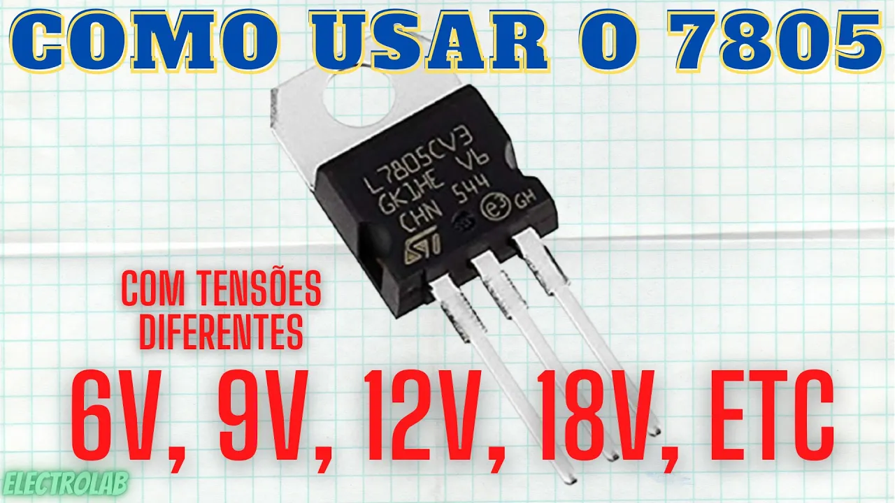
Como regular tensões de 6V, 9V, 12V, etc, numa fonte com um LM7805!!
100.3K
Three practical techniques for voltage regulation above 5V using the 7805: (1) Diode series method - connect silicon diodes (1N4007) in series with the reference pin; each diode drops 0.6-0.7V, so two diodes yield 6.2-6.4V output. (2) Zener diode method - connect Zener diode in reverse bias between reference pin and ground; output equals Zener voltage plus 5V. A 9V Zener produces 14V output, while a 4.7V Zener produces approximately 9.7V. (3) Resistive divider with potentiometer for fine adjustment. The input voltage must be at least 2V higher than the desired output for proper regulation. These techniques allow obtaining stable voltages like 6V, 9V, and 12V using common components.
Click to watch →

Complete Class 12th Physics | 100 Marks Confirmed 🔥 | NEET 2025 | Yawar Manzoor
48K
A Zener diode is used as a voltage regulator. When connected in reverse bias with a load, it maintains a constant voltage (Zener voltage, V_Z) across the load regardless of changes in input voltage or load resistance. Different Zener diodes are available with different Zener voltages (e.g., 10V, 20V). In a Zener diode voltage regulator circuit: the Zener diode maintains constant voltage V_Z across the load; the current through the Zener diode is I_Z = (V_in - V_Z)/R, where R is the series resistance; the load current is I_L = V_Z/R_L. When V_in < V_Z, the Zener diode is off and V_out = V_in; when V_in ≥ V_Z, the Zener diode conducts and V_out = V_Z (constant).
Click to watch →

SEMICONDUCTOR ELECTRONICS in ONE SHOT || All Concepts, Tricks & PYQ || Ummeed NEET
254.5K
Zener diodes operate in reverse breakdown to maintain constant voltage. In heavily doped junctions, Zener breakdown occurs when the electric field breaks covalent bonds directly. The Zener voltage (Vz) remains constant regardless of current, making Zener diodes ideal voltage regulators. In a regulator circuit with series resistor, the load voltage equals Vz, and excess current flows through the Zener. The current through the Zener is Iz = (Vs - Vz)/R - IL, where IL is load current.
Click to watch →

JEE MAIN 2023 : Mains Specific Topics | Most Expected Questions | JEE Physics | Eduniti
57K
In a Zener diode voltage regulator circuit, the Zener diode maintains a constant voltage across itself when operating in reverse breakdown. The minimum current through the Zener diode occurs when the input voltage is minimum (8V), and the maximum current occurs when the input voltage is maximum (16V). The current through the Zener diode is calculated as I_Z = (V_in - V_Z)/R, where V_Z is the Zener voltage (6V) and R is the series resistance. For minimum current: I_Z(min) = (8 - 6)/1000 = 2mA. For maximum current: I_Z(max) = (16 - 6)/1000 = 10mA.
Click to watch →

Zener Diode as Voltage Regulator | Viva-Voce | Practical File
58.9K
A Zener diode maintains a constant output voltage across a load by operating in reverse breakdown, where it conducts current and clamps the voltage at its Zener breakdown voltage (Vz), making it effective for voltage regulation in electronic circuits.
Click to watch →
Deep Dive
Using voltage dividers to set reference voltages in Operational Amplifier (Op-Amp) and comparator circuits.
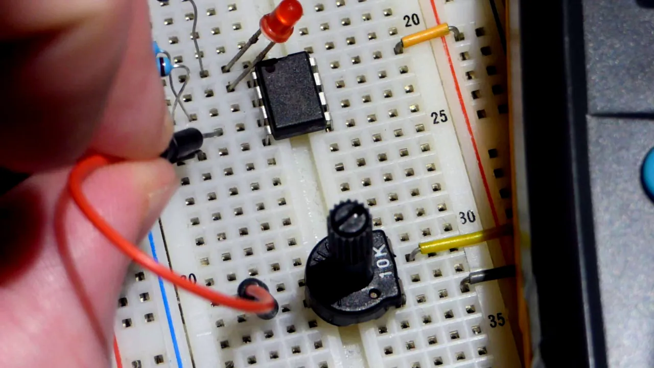
LM358 low voltage single supply op amp non inverting comparator circuit with LED load
34.9K
A voltage divider using two equal-value resistors (such as 100kΩ each) creates a stable reference voltage at the midpoint, providing half the supply voltage. For a 3.3V supply, this yields approximately 1.65V; for 5V, it yields approximately 2.5V. A trim potentiometer serves as an adjustable voltage divider, allowing precise control of the reference voltage by varying the resistance ratio. In a comparator circuit, the non-inverting input receives the signal to compare against this reference. When the non-inverting input exceeds the reference voltage, the output saturates high (near the positive rail minus 1.5V); when it drops below, the output saturates low (near zero volts). The LED connected to the output indicates the comparison result, lighting up when the output is high and turning off when saturated low.
Click to watch →

Ligando um dispositivo conforme a temperatura (no caso um coller) - LM35 e LM358
69.9K
This segment explains how to design the voltage divider and comparator circuits for temperature threshold detection. The LM35 sensor outputs 10mV per degree Celsius, so 50°C produces 500mV. A voltage divider using a 10kΩ resistor and 470Ω resistor divides a 12V supply to create approximately 520mV as the reference voltage. The LM358 dual operational amplifier functions as a comparator, with the non-inverting input receiving the sensor signal and the inverting input receiving the reference voltage. When the sensor voltage exceeds the reference, the output goes high (12V); otherwise, it goes low (0V). The LM358 is preferred over alternatives like the 741 because it doesn't produce residual output voltage when not activated.
Click to watch →

#32 Projeto de Comparadores de Tensão
23.2K
A voltage comparator using an operational amplifier compares a variable input voltage against a fixed reference voltage; when the input voltage exceeds the reference, the output saturates positively (activating connected components like LEDs), and when it falls below, the output saturates negatively (deactivating them). The reference voltage can be set using a voltage divider or potentiometer, and the comparator's behavior depends on whether the reference is placed in the non-inverting or inverting input.
Click to watch →

Proteção de Nível DC: Aprenda a Analisar esse Circuito Passo a Passo (Vídeo 4)
2.4K
Voltage dividers use resistors in series to create reference voltages from a power source, with each resistor creating a voltage drop proportional to its value. Operational amplifiers function as voltage comparators, outputting positive extreme when non-inverting input exceeds inverting input, and negative extreme when inverting input is higher. This combination enables circuits to make binary decisions based on voltage comparisons, forming the basis for protection and control systems.
Click to watch →

OP AMP as a Comparator🔥| OP AMP as Night Switch🔥| Ch#18 Electronics | Class 12
9.1K
To calculate the reference voltage (Vref) in a voltage divider circuit: Vref = VCC × (R2 / (R1 + R2)), where R1 and R2 are resistors connected in series. The current through the series combination is I = VCC / (R1 + R2), and Vref is the voltage across resistor R2. This formula allows precise setting of the reference voltage for comparator circuits.
Click to watch →
Voltage Divider Basics
Reference Voltage Relation
Formula Application
Example Verification
Voltage Divider Basics
0:00- 1
Core electronic circuit used repeatedly in schematics.
- 2
Standard form uses two resistors in series.
- 3
Connects between a voltage source and ground.
The Loading Effect and Inefficiency of Passive Voltage Dividers
While a passive resistive voltage divider is a fundamental circuit concept, it has severe limitations in practical electronics applications. It cannot maintain a stable voltage when a load is connected to its output; the load's input resistance acts in parallel with the divider's bottom resistor, which alters the total resistance and causes the output voltage to drop (known as the loading effect). Furthermore, resistive dividers are highly inefficient for power delivery because they continuously dissipate power as heat. Consequently, practical electronics design requires active alternatives, such as op-amp voltage buffers to prevent loading, or dedicated voltage regulators (like LDOs and buck converters) for efficient power management.
Understanding of basic electrical quantities: Voltage (V), Current (I), and Resistance (R).
Familiarity with Ohm's Law (V = I * R) and how to solve for different variables.
Concept of series circuits, specifically how current is constant and resistances add up in a single path.
Basic algebraic manipulation skills to understand and derive circuit equations.
The 'loading effect' and why resistive voltage dividers are not suitable as power supplies for heavy loads.
Practical applications of voltage dividers with analog sensors (e.g., photoresistors/LDRs, thermistors, and potentiometers).
Kirchhoff's Voltage Law (KVL) and Kirchhoff's Current Law (KCL) for analyzing more complex circuit networks.
Active voltage regulation techniques using Zener diodes and linear voltage regulator ICs (like the LM7805).
Using voltage dividers to set reference voltages in Operational Amplifier (Op-Amp) and comparator circuits.
131.9K views8.4Klikes0:59@adafruitOriginal Release: 2021-08-30
the voltage divider is one of the fundamental circuits used in electronics you'll find it used again and again in schematics once you know to look for it in its most common form the resistive divider two resistors are connected in series between a voltage source and ground to create a reference voltage [Music] the relationship between these resistor values determines that reference voltage available at the node between them [Music] we can use this simple equation to determine that voltage so with a 5 volt supply voltage a first resistor value of 10 k ohms and a second value of 20 k ohms the voltage available between the resistors should be about 3.33 volts and so it is thanks again math
Up Next

36:19
Arduino Photoresistor Tutorial: Build a Light-Sensitive LED Circuit
@paulmcwhorter
227.9K views•2019-08-27

30:32
Ultrasonic Transducers: Resonant Frequency Measurement and Horn Design
@imajeenyus42
229.9K views•2017-02-22

54:16
Polymer Environmental Degradation: Mechanisms & Stabilization
@iit
1.8K views•2012-07-10

33:39
How a Student's Question Saved a NYC Skyscraper from Collapse
@veritasium
22.8M views•2025-04-26
Related Study Plans & Knowledge Roadmaps
Structured learning paths in Engineering
engineering
Building Acoustic Levitators: Physics & Arduino
01The Physics of Sound and Standing Waves
02Piezoelectric Transducers and H-Bridge Drivers
03Arduino Programming: Generating 40 kHz Signals
+ 2 more learning modules
14h5 modules
Explore Roadmap
engineering
Building Peltier Cloud Chambers: Particle Tracks
01Cosmic Rays & Cloud Chamber Physics
02Thermoelectric Cooling (TEC) Fundamentals
03Custom Liquid-Cooling Loop Design
+ 2 more learning modules
18h5 modules
Explore Roadmap
engineering
Yagi-Uda Antennas: Modeling, Build & VNA Test
01Introduction to RF and Antenna Fundamentals
02Yagi-Uda Antenna Design Principles
03Antenna Modeling and Simulation in 4NEC2
+ 2 more learning modules
18h5 modules
Explore Roadmap
engineering
ECG Monitor Design: Op-Amps, Filters & Noise
01Electronics & Breadboard Basics
02Op-Amps and Instrumentation Amplifiers
03Bioelectricity and ECG Fundamentals
+ 2 more learning modules
18h5 modules
Explore Roadmap