


















MMANA GAL is a free numerical simulation program for antenna modeling that allows users to define antenna geometry, sources, and loads through a geometry tab, view and rotate the antenna model, calculate performance metrics including SWR and gain, and generate 2D and 3D far-field radiation plots to analyze antenna patterns and optimize designs for specific applications like DX communications.
MMANA GAL Antenna Simulator: Modeling and Analysis Tutorial
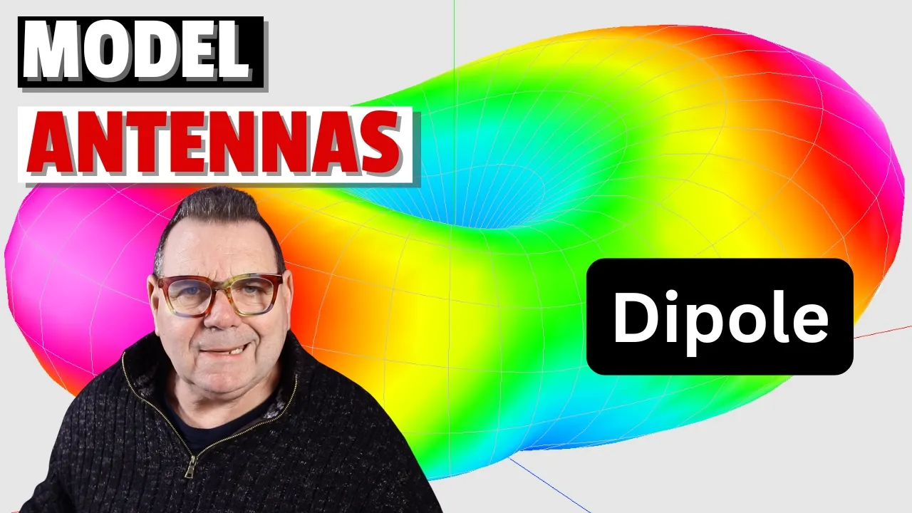
Added:Fundamental antenna concepts, specifically dipole and monopole designs, and how they radiate electromagnetic waves.
Key RF performance metrics such as Standing Wave Ratio (SWR), feedpoint impedance (R + jX), and antenna gain (dBi).
The mathematical relationship between frequency, wavelength, and the physical length of an antenna element.
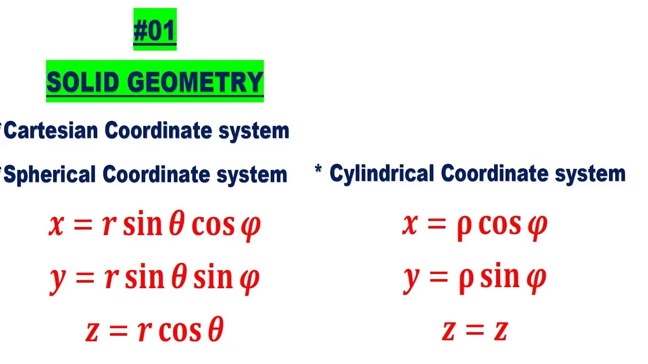
Basic 3D Cartesian coordinate geometry (X, Y, Z axes) used to map wire endpoints in modeling software.
Advanced optimization techniques within MMANA-GAL to automatically tune antenna dimensions for specific target frequencies and SWR.
Analyzing the effects of real-world environments, such as ground conductivity, elevation, and nearby structures, on simulated radiation patterns.
Translating virtual models into physical antenna builds, including accounting for wire insulation velocity factors and structural support.
Exploring alternative electromagnetic modeling software (such as NEC-2 or EZNEC) to understand the limitations of thin-wire simulation engines.
2.4K views37likes9:35Original Release: 2021-08-14
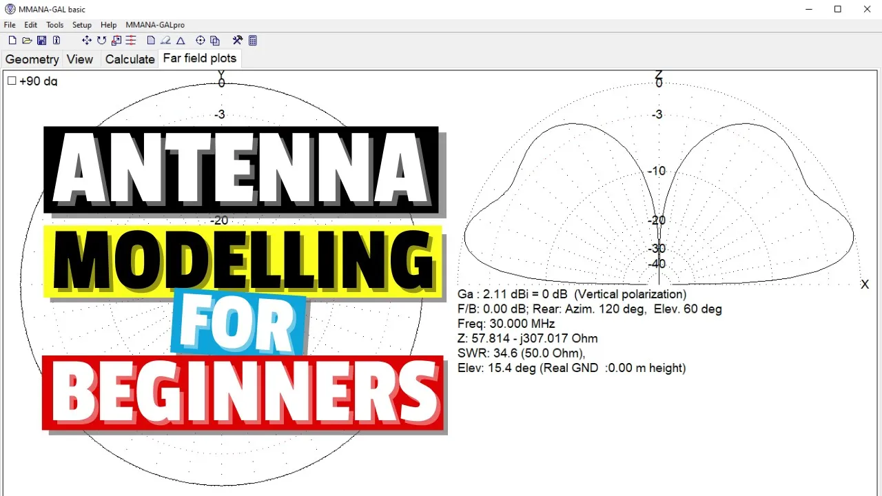
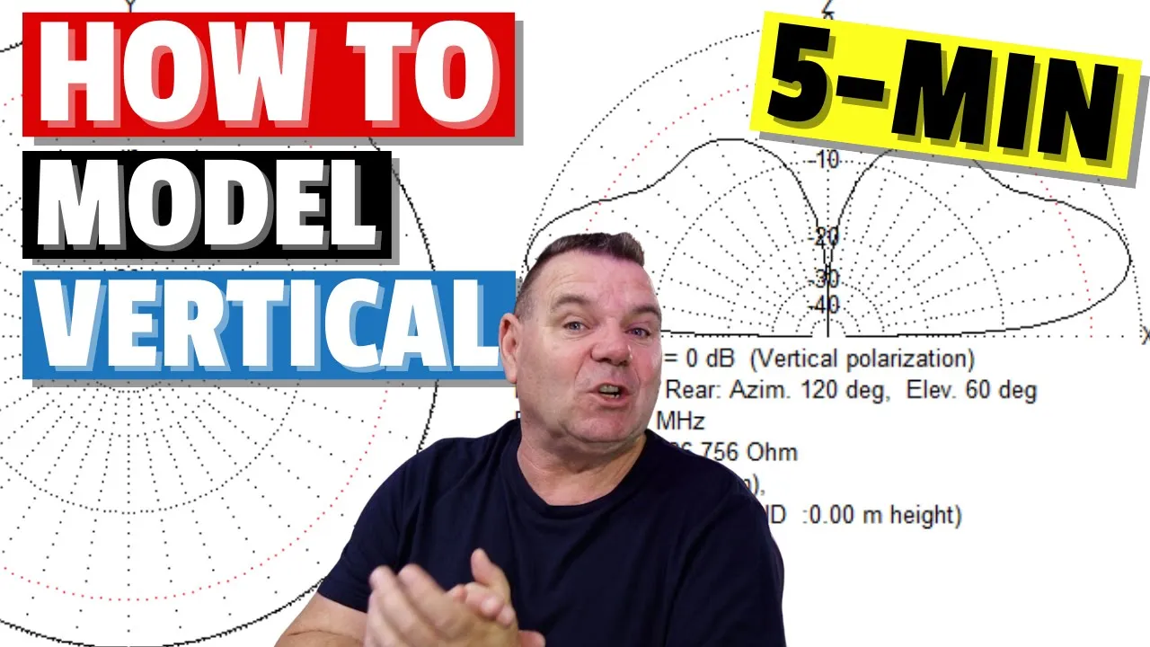
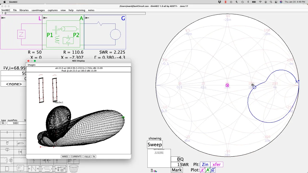
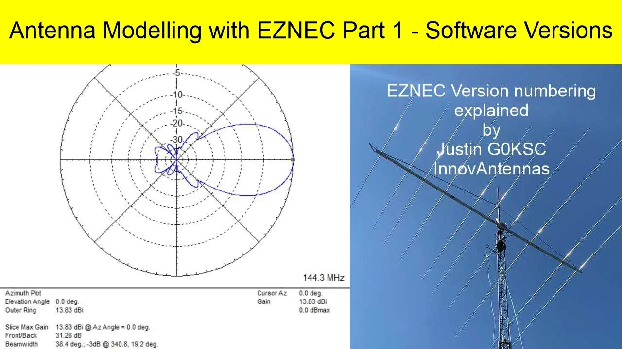
hello today we are going to go ahead and use the mana gal program to analyze an antenna that is going to actually serve to show us the capabilities of this program and uh well let's get started by the way the version that you're seeing right here of mana gao is the free version there is a pro version pro which is paid and but i'm finding that i'm using the free version and it's working very very well for me uh just a couple of things to note there's a menu bar at the very top with the usual buttons file will allow you to create a new button and you want to analyze an antenna from the ground up or you can open an existing file that you might have had or reopen one that you might have been working on before there are four tabs across the top and the first one is geometry it actually is where we define the antenna that we're working with and define the sources in other words how much voltage we're going to be applying and at which point and loads any sort of inductive coils or capacitances that we might have added to our antenna the next tab is view this will allow us to you hold down the mouse and move it down or sideways you're able to rotate and view your antenna in more detail you can select the middle point of the antenna to focus on and then use this to zoom in or zoom out and then the third button is really the main button for the uh for the program this is the calculate button this is actually what's going to be running the calculation for the modeling of our antenna notice that you have an excel like grid down at the very bottom here and you will have for each one of these rows you will have all of these parameters that are computed and are outputted by the program such as the swr the gain and the elevation at which that maximum gain was at and so on the other thing to note is that you also have ways to specify the grounds now to be fair i've only found any any use for the real option here why because we're not in free space that would be something like the space station uh it's not a perfect situation we're going to be dealing with a ground that is real when you select real then you select ground setup this window pops up in which you can actually specify dielectric constants and conductivity at least sieverts per meter and such about the ground and really it depends on how humid the ground is and properties of the ground whether it's rocky or close to the water and salty water etc i find that i leave the default values here and that seems to work fine with me of more importance maybe is this check box right here here by checking this you're able to tell the program to consider the use of radials which is very important for vertical antennas and you can actually enter the number of radials and the radius of the wire that you want to use so pretty much that's an introduction to this program when you finish this information here and you've defined the geometry you click on start and that will go ahead and give you the results here there are another there are a couple of other buttons that are very useful that i find one is optimization and the other one is plots we'll delve into those a little bit later the fourth tab is very useful in that it actually shows you the far field plots and this is an acid youthful view of your antennas if you're flying over the antenna and it'll show you if it's a focal antenna if it's focused in one direction or another it'll highlight those features think of a yagi a yagi antenna will definitely be focusing in one direction so you'll see that focusing here on the right hand side you have essentially an elevation plot so you're looking at the cross section in the case of a dipole it might be one big lobe if it's close to ground uh when a vertical you'll have two lobes and such and you'll be able to see at what point the maximum gain is found by the calculations of the program planned the other point is uh following uh the dx commander's example you can always define clicking this elevation button five degrees so you can actually see how well your antenna design would work for long dx contacts and uh and that's that's about it so let's go ahead and see an example click on the geometry tab and we'll go ahead and say for example let's create an antenna we're going to go ahead and name it vertical antenna we'll go ahead and define it to be from 0 0 0 0 the origin up to say about 10 meters remember the scale is in meters so you have to convert you know 32 feet to 10 meters and such and the other thing we want to leave is everything default for poles we'll go ahead and say we're going to put a source wire and it's going to be on an element one we get this one right here from element one the only element that we have and we're going to go ahead and place it in the center c now as soon as we hit enter it defines a one volt test current that is going to be a test voltage that is going to be running up and down the antenna and ac test voltage if we click on view there's our antenna right there as a matter of fact let's go ahead and change that source to the base which would be more of a realistic point we highlight the antenna right click on it and you'll see that there's an option now to move the source to the beginning of the wire so that drops the source down to here the little loop right there is the source the x would be a load we don't have a load on here we haven't defined it we can go ahead and zoom in not not very exciting because it's a single element we can rotate it we can hold the shift key and move this up and down fair enough calculate we'll go ahead and leave the ground set up with 24 radius which is pretty good and we'll leave it at a height of zero meters because radio i mean the vertical is going to be actually sitting on the ground with its radius we'll define it as copper wire and we'll go ahead and click start the program in 0.11 seconds has figured that we have a very high resistance 50.5 swr which is not good and a dbi of 0.08 but for this example is we'll leave it like that the fifa field plots show that it's a very symmetrical antenna but it does have a focusing for dx it may be a good antenna for dx of course the swr being an issue and other issues but if you highlight here you see that it's a 0.1 decibel dbi visible isotropic gain which is not bad at all and over here if you highlight up and down you'll see that it's at 18 degrees 19 degrees it's got 0.1 dbi not bad and then by clicking on elevation if we put 5 degrees elevation we were talking about that's the a good idea from callum uh to go in the dx commander to go ahead and give us an idea of how good a dx antenna this would be we get a minus 5.2 tbi at five degrees just something like that that pretty much is it well except let's go ahead and change this to seven point one five oh it'd be in ten meters we're thinking that this would be a good quarter wavelength antenna for for the 40 meter band so we'll go ahead and leave that there leave everything the same click on start now we're talking now our swr has dropped to 1.71 resistance is 34.
gain is 1.74 plus 0.72 and the elevation is 25.9 our far-field plots show 1.7 dbi which is not bad at all elevation we click on elevation and we put in 5 degrees of elevation and we see that we're at minus 5.0 dpi that's what the numbers show that pretty much is uh is a quick introduction in the next videos we'll look into optimization and the plots button but that gives you an idea of how easy it is to enter an antenna in the mana gal program
Up Next
22:58
How to Build a Compact High-Gain 2.4GHz Yagi Antenna
@andrewmcneil
33.7K views•2015-12-11

30:32
Ultrasonic Transducers: Resonant Frequency Measurement and Horn Design
@imajeenyus42
229.9K views•2017-02-22

54:16
Polymer Environmental Degradation: Mechanisms & Stabilization
@iit
1.8K views•2012-07-10

33:39
How a Student's Question Saved a NYC Skyscraper from Collapse
@veritasium
22.8M views•2025-04-26
Related Study Plans & Knowledge Roadmaps
Structured learning paths in Engineering
engineering
Building Acoustic Levitators: Physics & Arduino
01The Physics of Sound and Standing Waves
02Piezoelectric Transducers and H-Bridge Drivers
03Arduino Programming: Generating 40 kHz Signals
+ 2 more learning modules
14h5 modules
Explore Roadmap
engineering
Building Peltier Cloud Chambers: Particle Tracks
01Cosmic Rays & Cloud Chamber Physics
02Thermoelectric Cooling (TEC) Fundamentals
03Custom Liquid-Cooling Loop Design
+ 2 more learning modules
18h5 modules
Explore Roadmap
engineering
Yagi-Uda Antennas: Modeling, Build & VNA Test
01Introduction to RF and Antenna Fundamentals
02Yagi-Uda Antenna Design Principles
03Antenna Modeling and Simulation in 4NEC2
+ 2 more learning modules
18h5 modules
Explore Roadmap
engineering
ECG Monitor Design: Op-Amps, Filters & Noise
01Electronics & Breadboard Basics
02Op-Amps and Instrumentation Amplifiers
03Bioelectricity and ECG Fundamentals
+ 2 more learning modules
18h5 modules
Explore Roadmap