
![[ VẬT LÍ 12 - ÔN TẬP KIỂM TRA GIỮA KÌ 2] Chữa đề GK02 - số 01 | IPCLASS](https://i.ytimg.com/vi_webp/Vuk8yhSi73s/maxresdefault.webp)




















This video demonstrates how to construct a 14dBi Yagi antenna for 2.4GHz Wi-Fi applications using brass tubing (8mm square, 150mm long) for the boom and copper wire (1.5mm diameter) for the elements. The design features three parasitic elements spaced at 30mm intervals with a 60mm gap to the reflector, and a looped dipole driven element positioned 20mm from the first parasitic element. The antenna achieves approximately 10% better signal strength than commercial alternatives while maintaining a compact 200mm footprint, making it suitable for portable Wi-Fi range extension or FPV drone applications.
How to Build a Compact High-Gain 2.4GHz Yagi Antenna
Added:Fundamentals of electromagnetic wave propagation and the mathematical relationship between frequency (specifically the 2.4GHz ISM band) and wavelength.
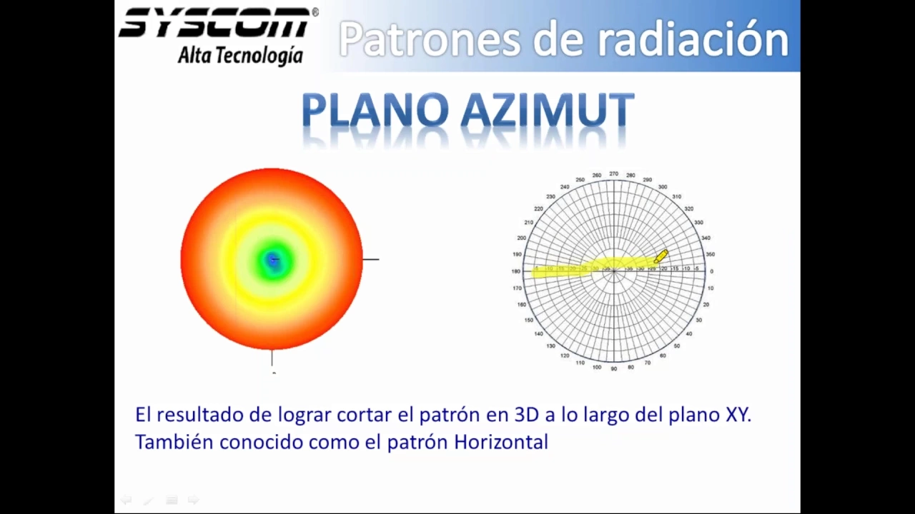
Basic antenna theory concepts, including gain (dBi), radiation patterns, directivity, and polarization.
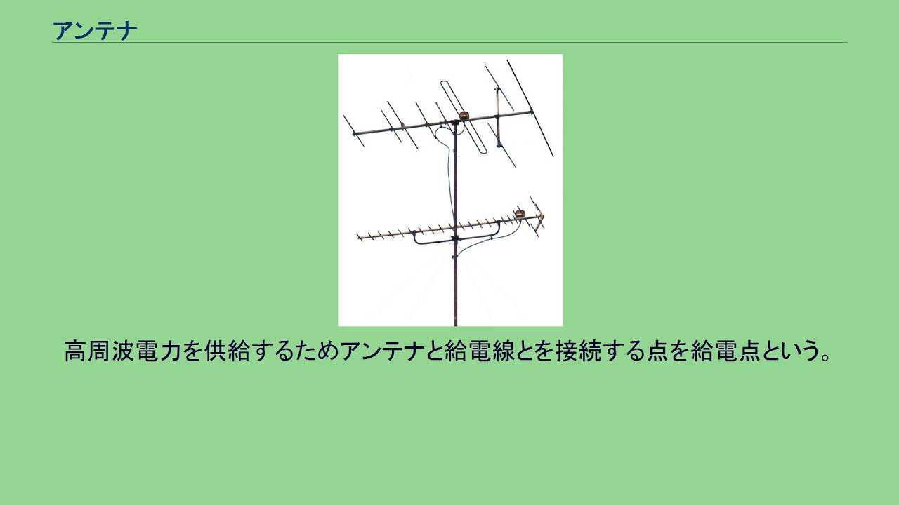
The fundamental anatomy and operating principles of a Yagi-Uda antenna, distinguishing the roles of the reflector, driven element, and directors.
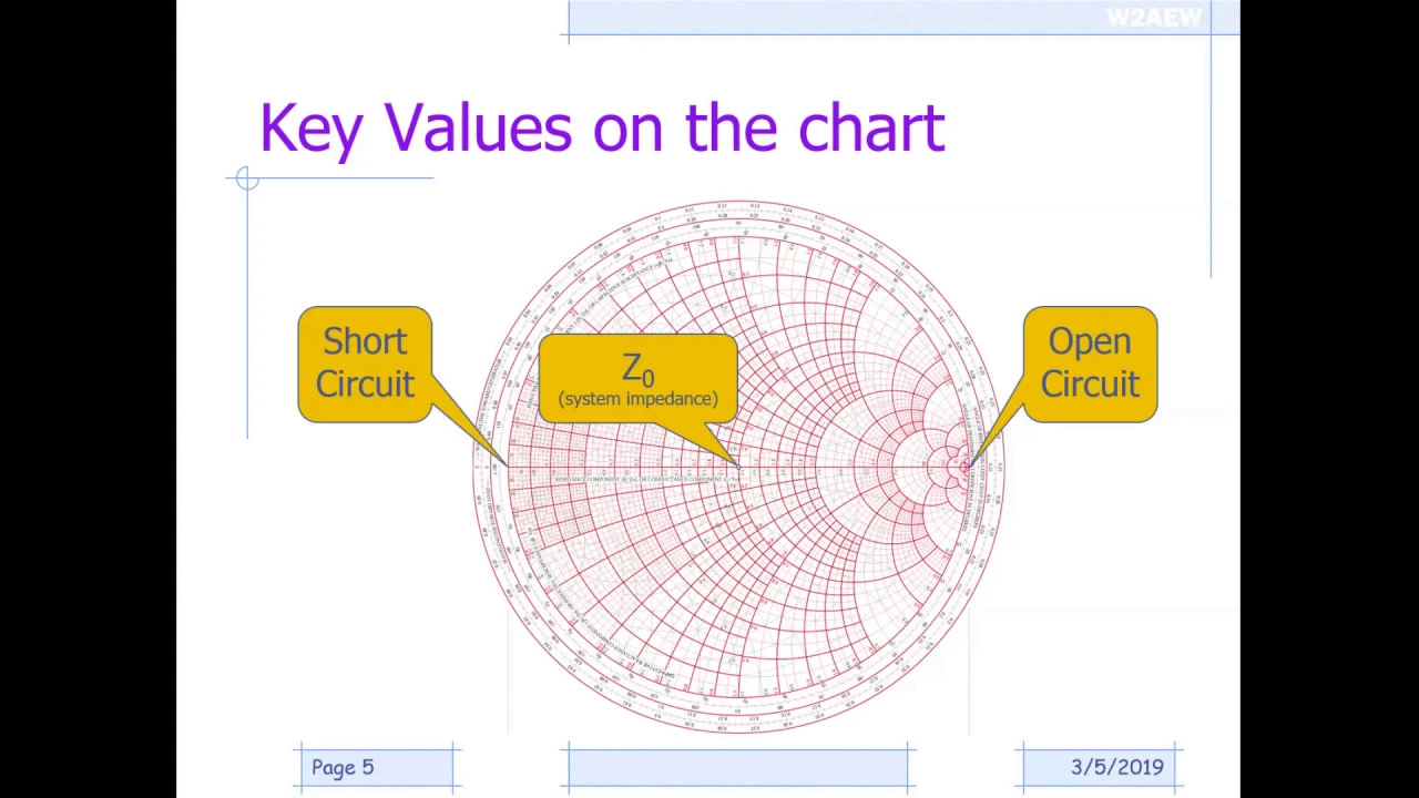
Impedance matching principles and transmission line basics, particularly understanding the significance of VSWR (Voltage Standing Wave Ratio) in a 50-ohm system.
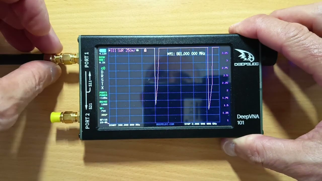
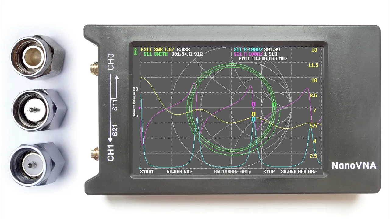
Antenna testing and calibration techniques using a Vector Network Analyzer (VNA) to measure S-parameters (S11/Return Loss) and resonant frequency.
Computer-aided electromagnetic simulation using software such as 4NEC2 or HFSS to model and optimize custom antenna geometries virtually.
Practical deployment strategies for directional antennas in wireless communications, such as establishing long-range point-to-point Wi-Fi links.
Exploration of alternative high-gain antenna topologies, such as helical antennas for circular polarization, microstrip patch arrays, or parabolic reflectors.
33.7K views456likes22:58Original Release: 2015-12-11
so I've been trying to find a decent Yari antenna on uh Amazon and eBay and a few other online sites and uh it's just not out there they always tend to be these uh cheap yagi antennas either rebranded and uh you know with a slightly higher price tag but you can pick these up for as low as uh £3 and uh free shipping on eBay and uh you'll find these in um you know on other websites where sellers have uh bumped up the price a little bit just to try and trick you into buying it thinking that you're spending more money you'll get a better quality Yari but they're not they're always you know around this kind of design either with this kind of driven element or uh this uh looped driven element here which is slightly better than this one this one's a dipole uh type element and uh it does have a Balon this one's not it's just a straightforward looped dipole and this one I picked up actually looked nothing like the uh picture on the website when I actually got it and take it I've taken a closer look at it it's just one of these with a different driven element on and it's been cut off here so you know it's it's h no better than uh this one in fact it's probably worse because it hasn't got the uh parasitic elements but I haven't tried them side by side so I don't really know so I've decided to try and uh design my own uh 2.4 GHz yagi specifically for Wi-Fi butth you know you can use it for fpv if you wanted to and other things like that but I just can't find a decent Yari out there so I thought I'll have a go at to making my own now I want to keep the footprint of mine down I don't want it to be as long as this one for instance uh it's a lot more difficult to uh design an antenna with uh a lot of gain you know quite a powerful longdistance antenna but keep it keeping its footprint small it's a lot easier to buy a big or build a big whopping antenna that you know has got decent range and distance but if it's too big you know it's it's not usable I want something where you can just throw it in your backpack and go out and uh you know bring it out when you actually need some some distance over Wi-Fi or whatever it is you're doing so I want to keep my footprint around the same size as this one which is about 200 mm long so here are two yagi designs that I've uh come up with and settled them I uh had to go building quite a few different designs I started out of making them out of cardboard and uh you know and wood and uh I've explained how to do that in previous videos but these two actually show a lot of promise and as I said I want to keep the footprint at um 200 mm 200 mm from the reflector to say the first driven element now these ones are slightly shorter cuz uh they are just basically prototypes I just wanted to build them up and see how they work and uh one way to actually increase the gain of the antenna but still keep its footprint small is to add multiple elements like this one here now this one is uh a nice little performing Yari and I'm going to show you how to build this one in another video but this one here is the one that I'm going to show you how to build in uh this video so in this video then I'm going to show you how I made uh this Yari antenna and I have to admit that as far as looks go I do prefer this one over this one although looks aren't everything because this one is slightly more powerful than this one but uh as I say in this video I'm going to go over the steps on how you actually make this one and this one I'll show you in the next video so the two main materials that I'm going to be using to build this little yagi antenna then I've got this square box tube in here it's uh brass tubing and it's 8 mm each side and it's also 150 mm long so I'm going to be using that box tube in for the boom and for the elements themselves I've got this uh Copper Wear and this is 1. 5 mm thick in diameter so it's still quite flexible but in short length it's quite rigid and holds its shape well so this should work out well for the elements so I've measured off the spacings for the uh three parasitic elements and then the back reflector element here on the brass tubing so what I actually did I uh measured in from the end of the uh tube in here just 5 mm and then I put my first Mark where I want my final parasitic element on the end of the AR here and I've just got a square and I actually just put a mark on each side of the uh brass tube in here just to make it a lot easier so I uh measured off this first one here and then I measured off 30 mm the space in between the uh parasitic element here and this second parasitic element and uh I put a mark just uh like I did for the first one there and then I measured off another 30 mm for the final parasitic element here and then I measured a gap of 60 mm which is the gap from the uh first parasitic element here to the actual B reflector now the main driven element is going to go in the middle of the first parasitic and the reflecting element but that's going to be completely separate for the boom so I don't need to mark that off so then I'll just put my final Mark here for the reflector and again I just drew the line all the way around the boom there so next what I'm going to actually do is use my bradle here to put an indentation right at the top of the line here right up next to this side wall of this brass tubing and then a second one around here up to the side wall here at the bottom of the tubing and do that to all the elements where I want to actually drill the holes and because I don't have a drill press what I'm going to do is flip it over to the opposite side and do the same on the opposite side if you don't have a drill press you want to try and drill your holes on each side independently and that way you'll get them nice and straight if you try to drill all the way through and one go without a drill press then you will get them slightly bent you won't get them straight but of course if you do have a drill press then you can actually drill all the way through and save yourself a little bit of time so the holes punched on both sides of the boom now top and bottom of each Mark and the same on the opposite side so what I'm going to do now is use the Dremel to actually drill the holes using a 1.5 mm drill bit so now that I've got all the holes actually drilled in the boom itself I'm now going to start making the elements now with this particular yagi I find it a lot easier to start at the end here with the smallest parasitic element and work my way backwards to the uh reflector itself now because the elements are going to be made in this U shape like this one here what uh I actually do and find easier is if you make all the elements first and make them uh slightly longer than what you're actually going to need the uh smallest uh parasitic element this one here is uh 15 mm this one is 16 mm and the final one here is 7 18 mm so it's really easy to uh remember those measurements so what I'm going to do then is just measure off a piece of the copper wire here at 45 mm and then I'm going to put another Mark roughly in the middle at around uh 22 1/2 mm it doesn't need to be precise it's just so I know where to actually put my uh curve in there and that can trim these legs away then so next I take my copper wire and I've got here a 3 mm drill bit that when to use to actually Bend round to put the curve in and I just find that 3 mm is the perfect size especially when you're using uh 8 mm Square Tubing like this so basically just put it up against the drill bit like so roughly where that Mark is and applying some pressure just gently bend the copper wire around that curve so you get a nice even curve all the way around and then once you've got it bent LAX so you can just trim this off and then repeat until you got all your elements made so now that I've got all my elements bent I need to start trimming them down to size now I want a small amount of the uh leg to actually penetrate the boom on the side here but uh I don't want it long enough where it's going to take up all the space so I can't get the legs in the opposing element on the other Sides Now what I've done I've got my ruler and I've got it bang on the 50 mm that this element needs to be and remember that we're taking the measurement from the side wall here so I need to trim a little bit of that waist off those legs there so I've got my uh needle noose pliers just come at the side here and then I can remove the element and then that way I know I can trim back some of these legs but still leave a little bit protuding through so I can actually solder it in place so I've trimmed away the waist and because I've got them held in these needle noose pliers I know that I've got these two lengths here actually uh penetrating the boom but not going to be long enough to interfere with the opposing element now to make it a lot easier to solder together you want to actually pre-tin around the holes on the boom here and also pre-tin the legs now I find it a lot easier to actually get in with the soldering iron and flow some solder around these holes and then actually get a small blow torch heat it up and give it a quick tap on this piece of wood here and the solder actually falls through the holes and leaves it nice L tinned up around the holes themselves so if you get yourself a small blowtorch like this one heat up the solder around the holes and as soon as it starts to go molten give it a quick tap so I've got the elements all pre-tinned and in place there I've just measured done with the ruler but now I've uh made this little jig here that I can actually tighten up around the boom and I can have the elements resting on these two pieces of scrap wood and uh I don't have to worry about making sure that those elements are at nice right angles to the boom you could also use a vice as well but I found that my Vie because it's metal was just acting as a big heing but I was able to do it if I turn the iron up quite high so I've Got The Jig in place there and tightened up I'm just uh doing one last final measurement just to double check that it is 15 mm at the peak of that curve there on both of these elements and then what I can do is just get in at the side there with the soldering iron and start soldering those in place and it's very very easy now because I've pre-tinned everything it's just a matter of getting some heat in there and getting it all flowing so I've got both legs on both sides actually solded up so what I can do now is remove this little jig and then get in there again with the soldering iron just to tidy these up a little bit but what I can do is just apply heat to opposite sides of these legs and let it cool down and that way the uh solder on one side will hold it in place while this side goes molten let that cool down and then do the opposite side and you can do a much neater job that way so I'm just soldering this second element in now and if you take your time to make a little jig like this it does make it all much easier so now that I've got the three parasitic elements in place I'm now going to move on to creating the main driven element for this antenna I've also put some heat shrink tubing around the boom here just to uh insulate the main driven element from the boom you don't want the main driven element to come into contact with the boom otherwise the antenna will not work so I've got a length of the copper wire here the same copper wire that we've made the elements out of so far and uh I've cut it off at 126 mm that's uh one full wavelength at 2.4 GHz and uh I've measured in a quarter wavelength from each end which is 31.5 mm and put a black mark on these positions here so here I've got a piece of wooden doweling it's actually 6 mm in diameter and I'm going to use that to put some bends just where this black mark is just as I did with the uh parasitic elements so I'm going to bend it around where that black mark is until I get this part of the uh copper wire all the way around the other side so I've got the bend in this side so I'm just going to do the same on the opposite side so these two ends actually meet in the middle now now I'm going to connect all this up with this short pigtail here so I've already prepared it I've got an SMA connector on the end and I've flared the outer braiding out here and the inner core here so I created this t-shape and I'll strip this back and cut away any excess just so I can actually solder it directly onto the uh main driven element like so now as for the length of this what I've done is uh I've changed a measurement with this uh particular design of yagi antenna and I'm getting slightly better results if you move the main driven element just 20 mm away from the first parasitic I used to put the main driven element dead center between the first parasitic and the back reflector here but moving it slightly closer I'm finding I'm getting better results so 20 mm away from the first parasitic is is where the main driven element is going to sit and as for the length of the uh pigtail itself what I've done I've just measured back from uh where the main driven element is going to be positioned roughly to the end of the boom so I think we're about 6 mm over the boom and that should be enough for me to actually connect that to a Wi-Fi card on the back here so I've got the pigtail solded onto the main driven element there now I prefer to use this kind of driven element which is a looped dipole it Loops back on itself and uh with this particular driven element I don't feel that there's any real need to put a dipole on this not at these kind of high frequencies anyway it does run slightly higher than uh you know you would like but uh actually adding a Balon is quite lossy so any kind of benefit you'd get with this type of loop dipole by adding Balon it would negate because it's uh so lossy and uh you know it would even itself out but if you were going to use this kind of uh dipole for instance as a main driven element on a Yari you do need a ballon with this and this is what this piece is here we've got a quarter wavelength here and a quarter wavelength here and uh you have a quarter wavelength of ballon I just like to wrap them back around itself on the coax to keep it tight and I would normally cover this with some heat rink tubing as well but I don't particularly like these I think you get much better gain and performance out of using a driven element like this one so I've got the main driven element in place then what I'm going to use to hold it in place is I'm going to put a small amount of epoxy putty over the top here just to cover those joints and protect them and I'm going to drizzle a little bit of epoxy on the bottom here just to hold that in place and finally I'm going to use some more heat shrink tubing over the top of the coax here just to hold that down as well and that should be more than strong enough now to make the B reflector I've cut a piece of the copper wire 90 mm long and I've put a small black mark in the center here at 45 mm and I'm going to be bending it round the drill bit just like I did with the parasitic elements so again I've got my 3 mm diameter drill bit so I'm just going to bend it around there nice and slow just like before just get that curve nice and uniform so I'm using the same technique to measure the reflector as I did with the parasitic element so I've just got it mounted through the holes there and the uh reflective element the wants to protrude out from the side of the boom itself that to 38 mm at the peak of the curve there so that's roughly just about 38 mm the actual measurement of the reflector is something that you can actually experiment with making it slightly smaller or slightly longer but again I going to use my needlenose pliers put it up to the side of the uh boom there extract the element and then I know that I can trim back the legs of these and just leave about 2 mm protruding in so I get a nice solder joint so I've got the uh B reflector soldered in place so what I want to do now is add a little platform on the back here just uh like so I've got a piece of PCB board here but uh doesn't have to be PCB it could be some kind of plastic or thin wood and I'm going to rivet it to the back and what I'm hoping that will do is give me a nice platform to hold my Wi-Fi card in place especially if I fasten it on with some velcro as well so I've got the platform riveted in place there and I'm quite pleased how that's actually come out but uh what I want to do now is drill a hole through the boom itself about here and uh what I'm actually going to do is tap that out so I can attach a small tripod to actually hold all this in place so to test its performance then I'm going to test it alongside the turbo tener which you know is not a bad yagi antenna by any means but it's just not worth the uh price tag that most sellers ask for it now I am using identical Alpha cards as well so it should be a fair test so quick test then I've got my yagi set up on the right of the screen and the Turbo tenis setup on the left both identical Alpha cards so let's give them both a quick scan so we'll let them both settle down so now that they've settled down they've both picked up a similar number of access points but if you look at the access points on the right that my yagi has picked up it's definitely 10% more signal strength on the majority of those access points so it's performing much better than the uh turbo tener and remember the turbo C has uh an extra two parasitic elements compared to mine so I'm really pleased with uh this little test it definitely is performing better than the turbo tener so not a bad little performing design this one I do actually like this one as far as uh Aesthetics go uh this one is my uh favorite of the two Yaris that I want to show you but um it definitely outperforms the turbo tener even though we've got two less uh parasitic elements on this one that I've made but uh how I'm going to take this forward now I want to add possibly another two parasitic elements even maybe three still keeping it in that small fo factor I don't want to go any longer than 200 mm from the reflector to the end parasitic there so I still want to keep it as a small footprint but I think I can add at least two parasitic elements to this and uh still keep it nice and small in that footprint design so as you saw in the test as I say definitely uh outperformed the uh turbo tener the picked up a similar amount of um wireless access points as you saw but uh if you actually take a close look at the uh test part of this this video you'll see that there's at least a temp % increase along the most of those access points that it actually did pick up so I'm quite pleased how this is actually turned out so I hope you found this uh video useful and interesting and you have a go making your own uh yagi antenna much better to actually make one than uh buy one off eBay any day of the week but um you know any questions comments drop them below and uh and as I say I know there are a lot of people out there who are fans of the yagi antenna some of my yagi antenna builds in the past have been uh some of my most viewed videos so as I said at the beginning I do have a second design to uh show you that really does show promise as well and uh hopefully that'll be on the channel in the next week or so but uh hopefully you enjoyed this video and hopefully you'll join me for the next one
Up Next

5:18
Build a 2.4 GHz Yagi WiFi Antenna: Design & Performance Test
@electrictechnic9740
45.6K views•2020-05-31

30:32
Ultrasonic Transducers: Resonant Frequency Measurement and Horn Design
@imajeenyus42
229.9K views•2017-02-22

54:16
Polymer Environmental Degradation: Mechanisms & Stabilization
@iit
1.8K views•2012-07-10

33:39
How a Student's Question Saved a NYC Skyscraper from Collapse
@veritasium
22.8M views•2025-04-26
Related Study Plans & Knowledge Roadmaps
Structured learning paths in Engineering
engineering
Building Acoustic Levitators: Physics & Arduino
01The Physics of Sound and Standing Waves
02Piezoelectric Transducers and H-Bridge Drivers
03Arduino Programming: Generating 40 kHz Signals
+ 2 more learning modules
14h5 modules
Explore Roadmap
engineering
Building Peltier Cloud Chambers: Particle Tracks
01Cosmic Rays & Cloud Chamber Physics
02Thermoelectric Cooling (TEC) Fundamentals
03Custom Liquid-Cooling Loop Design
+ 2 more learning modules
18h5 modules
Explore Roadmap
engineering
Yagi-Uda Antennas: Modeling, Build & VNA Test
01Introduction to RF and Antenna Fundamentals
02Yagi-Uda Antenna Design Principles
03Antenna Modeling and Simulation in 4NEC2
+ 2 more learning modules
18h5 modules
Explore Roadmap
engineering
ECG Monitor Design: Op-Amps, Filters & Noise
01Electronics & Breadboard Basics
02Op-Amps and Instrumentation Amplifiers
03Bioelectricity and ECG Fundamentals
+ 2 more learning modules
18h5 modules
Explore Roadmap