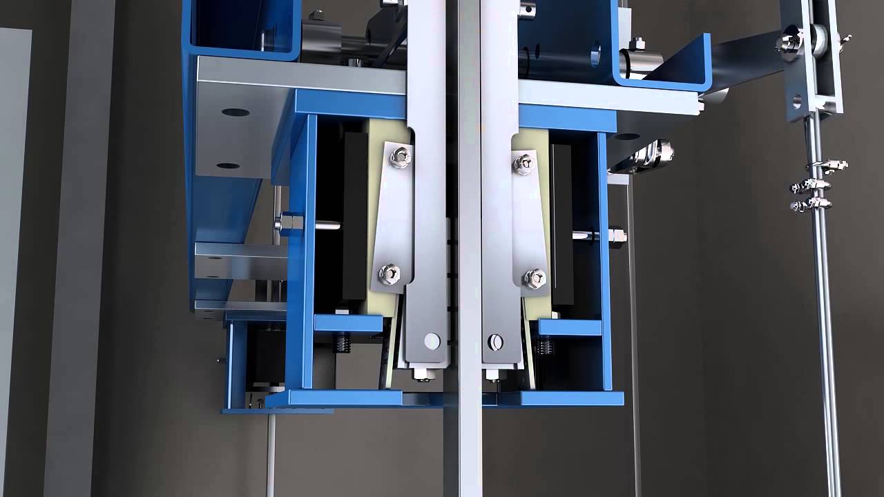
An elevator's governor-safety device prevents cab falls by automatically activating when rope tension drops or speed exceeds safe limits; the governor pulls a linked rope that engages a wedge on the emergency stop device, pressing it against the guide rail to halt the cab's descent.
Rope Elevator Governor & Safety Device | TOSHIBA Machine Room Explained
Added:Deep Dive
Basic mechanical principles of traction elevators, including the roles of the hoistway, car frame, guide rails, and counterweight.

Module 3 - Lecture 2 Classifications of elevator Part 1
562
Traction elevators operate on a pull mechanism using steel ropes or belts wrapped around a grooved pulley (sheave). One rope end connects to the electric motor, while the other connects to the lift car. A counterweight, composed of stacked steel plates in a frame, balances the car's weight to reduce motor workload and improve energy efficiency. Key components include the elevator car, traction machine, sheaves, counterweights, hoistway, guide rails, and machine room. The counterweight moves alongside the car in the shaft, guided by rails on the back wall. This balanced system reduces power demand and enables smoother, more efficient vertical transportation compared to hydraulic alternatives.
Click to watch →

Elevator Basic Components | Part-3 | Elevator Hoistway | Lift | in Urdu/Hindi
17.7K
The elevator hoistway is a vertical shaft structure where the elevator car travels between floors, containing essential components including guide rails (for both car and counterweight), counterweight, and landing pads. The counterweight system balances the elevator car's weight using the formula: Counterweight = (Car Weight + Rated Load) × 50%, where the car weight includes the complete structure, frame, lighting, flooring, and ceiling, plus the rated load capacity. The counterweight assembly consists of top assembly, bottom assembly, vertical profiles, and guide rails positioned at four corners to ensure smooth vertical movement.
Click to watch →

Elevator Systems Fundamentals: Dover B.E.S.T. Training Video
27.2K
Traction elevators have steel cables called wire ropes attached to the top of the car, extending over a drive sheave (pulley) generally located in a penthouse or room above the hoistway. After passing over the drive sheave, the ropes attach to a balanced weight called the counterweight, consisting of a frame filled with steel or iron weights. The counterweight improves traction and reduces power consumption. Wire ropes consist of many small wires twisted together for flexibility, wrapped around a fiber core that provides lubrication.
Click to watch →
Basic Principles in Building Conveying Systems
872
Traction elevators use electric motors driving pulley-like drive sheaves that hold steel cables (hoisting ropes) supporting both the elevator car and counterweight. Typically, three to eight cables per elevator with diameters from 1/4 to 1 1/4 inches (6-32mm) composed of multi-strand steel wire wound around hemp or polymeric cores. The counterweight equals the car's dead weight plus 40-50% of load capacity, creating balanced tension. Friction between cables and the drive sheave enables vertical movement. Various configurations exist: conventional hole systems with deep pits, telescoping systems with concentric plungers for shallow installations, and holeless systems with jacks beside rails. Dual jack configurations allow front and rear entrances while single jacks permit only front access.
Click to watch →
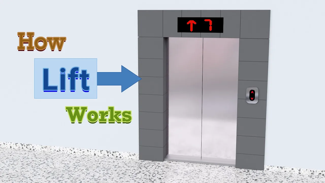
How do Elevators work(Animation)
924.5K
An elevator operates using an electric motor that turns a pulley, with a flexible rope winding or unwinding along which the elevator car rises or lowers. The counterweight travels along vertical guide rails in the opposite direction to the elevator car. The counterweight plays a crucial role in stability and energy efficiency by balancing the system, so the motor only needs to provide torque to tip the balance rather than lifting the entire weight.
Click to watch →
Deep Dive
The physical concept of centrifugal force and how rotational speed can be used to trigger mechanical mechanisms.

Урок 68. Явления в неинерциальных системах отсчета
72.9K
Centrifugal force is the inertial force acting on bodies at rest in rotating reference frames, directed radially outward with magnitude F = mω²R. It explains why riders on chain carousels feel pushed outward and why chains angle outward. Centrifugal mechanisms harness this force: centrifuges separate substances by density, centrifugal pumps move fluids, and centrifugal governors regulate machine speeds. These devices exploit the outward tendency of objects in rotating frames.
Click to watch →
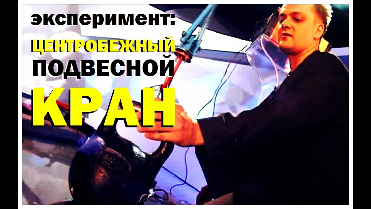
Галилео. Эксперимент. Центробежный подвесный кран
127.8K
A centrifugal lifting mechanism uses the principle that centrifugal force is proportional to the square of angular velocity, allowing small rotating masses to generate sufficient force to lift heavier objects; when the lifting load is released, conservation of angular momentum causes the rotating masses to speed up as they move closer together, maintaining the lifted position through continuous energy conversion between potential and kinetic forms.
Click to watch →

エヴァのバリア、俺にもつけたら最強なんじゃね?
10.7M
A barrier mechanism can be created using centrifugal force, where CO2 gas is injected and released while a rod spins, causing the barrier to open outward due to the rotational force; this demonstrates how centrifugal force can be applied to create protective barriers in mechanical systems.
Click to watch →

Complete Chapter 1 Rotational Dynamics Class 12th Physics #fightersbatch #newindianera
199.8K
Centrifugal force is the force acting on a particle performing circular motion which is directed away from the center. It is a pseudo-force that appears in the rotating reference frame. It is not a real force but is the reaction to centripetal force. Examples include coins on a gramophone disk moving outward and clothes in a washing machine dryer being pushed outward.
Click to watch →

КРУТИ! Как сделать Сейф из ЛЕГО / Без Техник
97.2K
This segment demonstrates how centrifugal force can be applied to create a mechanical locking mechanism. The LEGO safe uses two white pieces that initially block the door. When the safe is spun, centrifugal force pushes these pieces outward, away from the center, disengaging the lock and allowing the door to open. This principle shows how rotational motion can control mechanical systems without electronic components, making it an accessible physics demonstration for understanding force dynamics in everyday objects.
Click to watch →
Deep Dive
The fundamentals of electrical safety circuits (safety loops) and how mechanical switches interrupt power to industrial machinery.
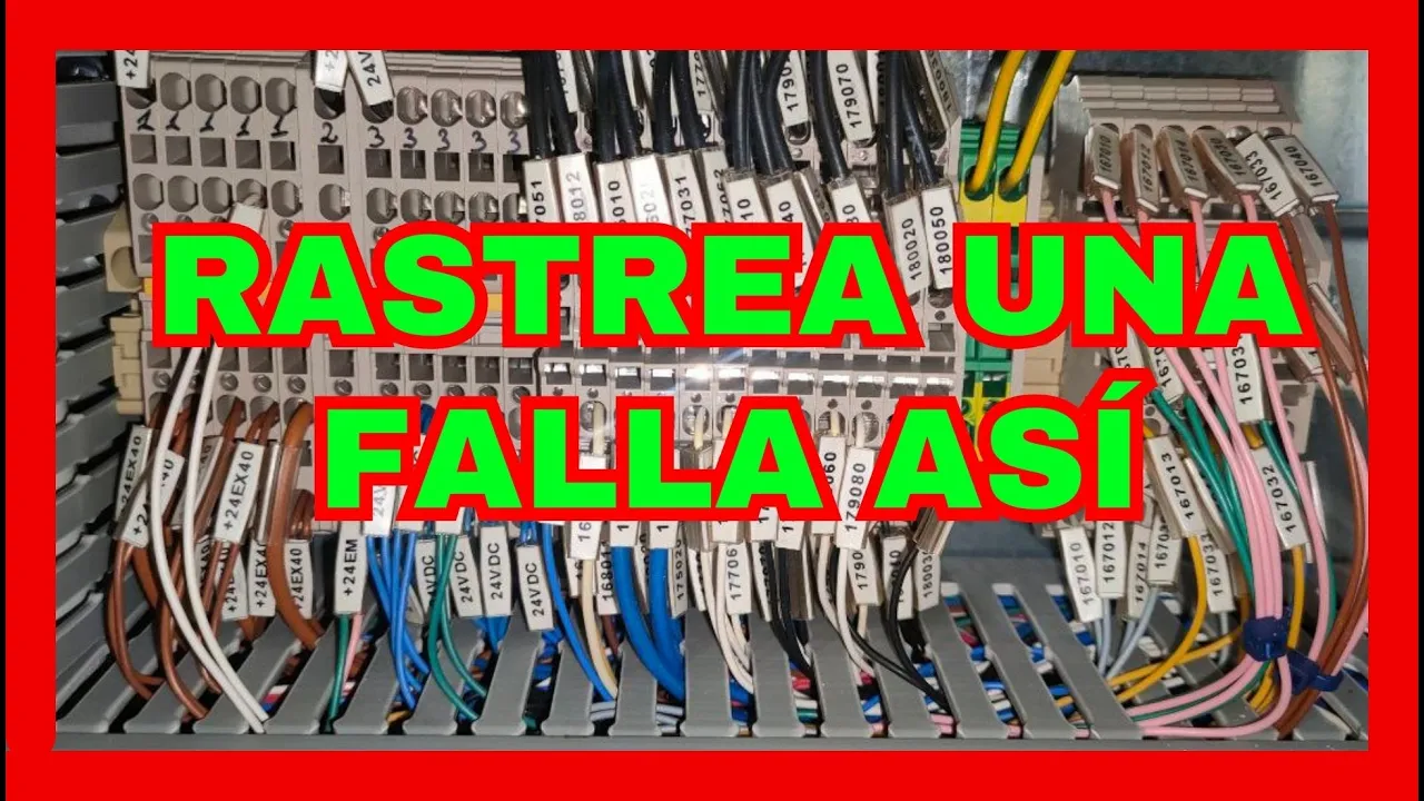
⚡⚡Análisis de Fallas Eléctricas en un modulo de Seguridad REAL
7.4K
Electrical safety is critical in industrial machinery and must be implemented during equipment creation. Safety modules require specific conditions to function, including normally closed (NC) contacts for doors and gates that open when safety devices are triggered. All safety components must be connected in series to ensure any single failure interrupts the entire safety circuit. Terminal blocks interconnect field equipment to the main electrical panel, serving as connection points for wiring from sensors and devices. Understanding these fundamentals is essential for implementing and troubleshooting safety systems.
Click to watch →

Ep 1: Disconnect Switch Basics & Safety Explained
948
A disconnect switch is a mechanical device that completely shuts off electrical power from a system, circuit, or equipment by creating a physical break in the electrical circuit, serving as the first line of defense for electrical safety; it operates in three main modes: load brake switches that interrupt power during operation, isolators that maintain disconnection after power is off, and safety switches that provide overall protection during maintenance or emergencies.
Click to watch →

Principe de l'Interrupteur de sécurité pour scie d'atelier et autres - 5mc #3
41.8K
A safety switch circuit for industrial machines uses a relay-based system with multiple components working together. The 230V power enters through two terminals and flows through a normally closed emergency stop button. Current reaches the start pushbutton and the relay's holding circuit. When the start button is pressed, it closes the circuit to the relay coil, which is connected to the neutral. The energized relay closes its three internal contacts, completing the motor circuit at 130V. This creates a self-maintaining path where the relay contacts now carry current to keep the coil energized, allowing the motor to continue running even after the start button is released.
Click to watch →

APRENDE A ANALIZAR FALLAS ELÉCTRICAS en un CIRCUITO de SEGURIDAD | teslamatic
16.4K
Safety circuits (emergency stop circuits) completely disable machinery when activated, including emergency stop buttons, magnetic contacts, and limit switches. These circuits cut power to main contactors, preventing operation until all safety conditions are restored. Safety relays use normally closed contacts (S11, S12, S21, S22) connected in series with safety devices. The circuit requires all safety conditions to be met before the relay energizes. Troubleshooting involves disconnecting safety devices and testing continuity between relay contacts. If continuity is open, the corresponding safety device is faulty. Each safety device must be verified individually for proper circuit function.
Click to watch →

Understanding Industrial Safety Circuits | Safety Relays, E-Stops, and Best Practices Explained
2.4K
Machine safety circuits confirm multiple device functionality before allowing operation, operating like a chain where all elements must satisfy conditions. Four energy sources require shutdown: mechanical, chemical/process, electrical, and pneumatic. A basic safety relay emits 24V DC through safety devices (estops, light curtains); if any device triggers, the circuit breaks and machine stops. A reset circuit with a push button is required because relays cannot automatically confirm safety status. This foundational understanding applies to both simple and complex safety systems.
Click to watch →
Prerequisite Knowledge
- Concept 01Basic mechanical principles of traction elevators, including the roles of the hoistway, car frame, guide rails, and counterweight.
- Concept 02The physical concept of centrifugal force and how rotational speed can be used to trigger mechanical mechanisms.
- Concept 03The fundamentals of electrical safety circuits (safety loops) and how mechanical switches interrupt power to industrial machinery.
Subsequent Learning
- Step 01In-depth analysis of safety gear types (instantaneous vs. progressive) and how they physically grip the guide rails during an overspeed event.
- Step 02Regulatory standards and codes for elevator safety, such as ASME A17.1 in North America or EN 81-20/50 in Europe.
- Step 03Procedures for periodic maintenance, calibration, and safety testing (e.g., category tests and governor pull-through force tests).
- Step 04The evolution toward Machine-Room-Less (MRL) elevator safety designs and electronic governor systems (PESSRAL).
Safety measures
Rope break action
Emergency brake
Stopping motion
Safety measures
0:00Playing Section
- 1
Additional measures prevent potential cab falls.
- 2
Systems are designed to ensure passenger safety.
Electronic Safety Systems (PESSRAL) and Machine-Room-Less (MRL) Technology
While traditional mechanical rope governors and safety gears in dedicated machine rooms have long been the industry standard, modern elevator engineering is increasingly shifting toward Programmable Electronic Systems in Safety Related Applications for Lifts (PESSRAL) and Machine-Room-Less (MRL) configurations. Traditional mechanical systems rely on physical governor ropes, tension weights, and centrifugal force, which require regular maintenance, are prone to mechanical wear, and demand significant structural space. In contrast, PESSRAL replaces mechanical governors with electronic sensors, absolute encoders, and software-driven safety controllers to monitor speed and position. This shift eliminates bulky ropes and pulleys, reduces mechanical failure points, and allows for real-time diagnostics. Furthermore, modern architecture increasingly favors MRL designs to maximize usable building space and lower construction costs, challenging the necessity of traditional machine-room-dependent safety layouts.
Deep Dive
In-depth analysis of safety gear types (instantaneous vs. progressive) and how they physically grip the guide rails during an overspeed event.

การใช้ลิฟต์และบันไดเลื่อนอย่างปลอดภัย
2.2K
Elevator safety gears include: instant-action gears (lock immediately upon activation) and progressive gears (gradually engage). Safety gears are mounted on the car bottom and activate when the speed governor detects overspeed. These systems prevent free fall by locking the car to the guide rails.
Click to watch →
SRH Safety device
235K
The overspeed governor is a critical safety device that monitors and controls elevator cabin running speed in real-time. It is precise, accurate, and stable in its operation. When the elevator cabin moves downward at excessive speed (overspeed), the overspeed governor activates by pulling the wire rope connected to the safety gear located at the lower part of the car. This action causes the safety gear to grip the guide rails and stop the car, thereby protecting against dangerous downward overspeed conditions.
Click to watch →
승강기기능사 ▶현장사진+기출중심 강의◀Ⅰ. 승강기개론 - 엘리베이터 개념과 구성요소
19.1K
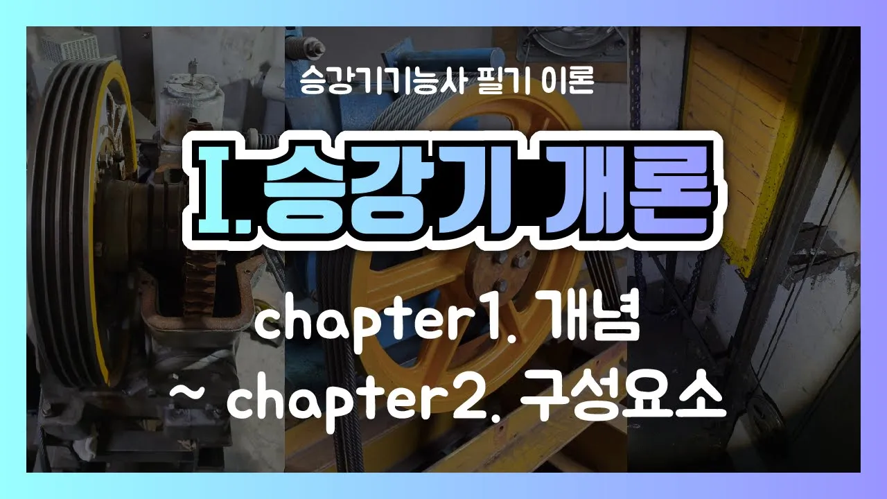
Wire rope specifications include strand count and core type, with termination methods (clamped most efficient, swaged, crimped). Guide rails maintain car alignment, prevent tilt, and provide emergency stop reference (T-shaped most common, sizes 8-32mm, 5m standard length). Emergency stop devices prevent falls: immediate action (safety gear) and gradual action (flexible guide clamps, flexible buffer clamps). Speed governors detect speeds exceeding 115% of rated speed (friction stop for low-speed, flywheel/disc for high-speed). Buffers absorb impact at bottom of travel. Counterweights balance the car with overbalance of 35-55% of rated load. Compensation systems (rope for high-speed, chain for low-speed) maintain balance as car moves.
Click to watch →
How elevator brakes actually work#education #howthingswork #science #shorts
29.4K
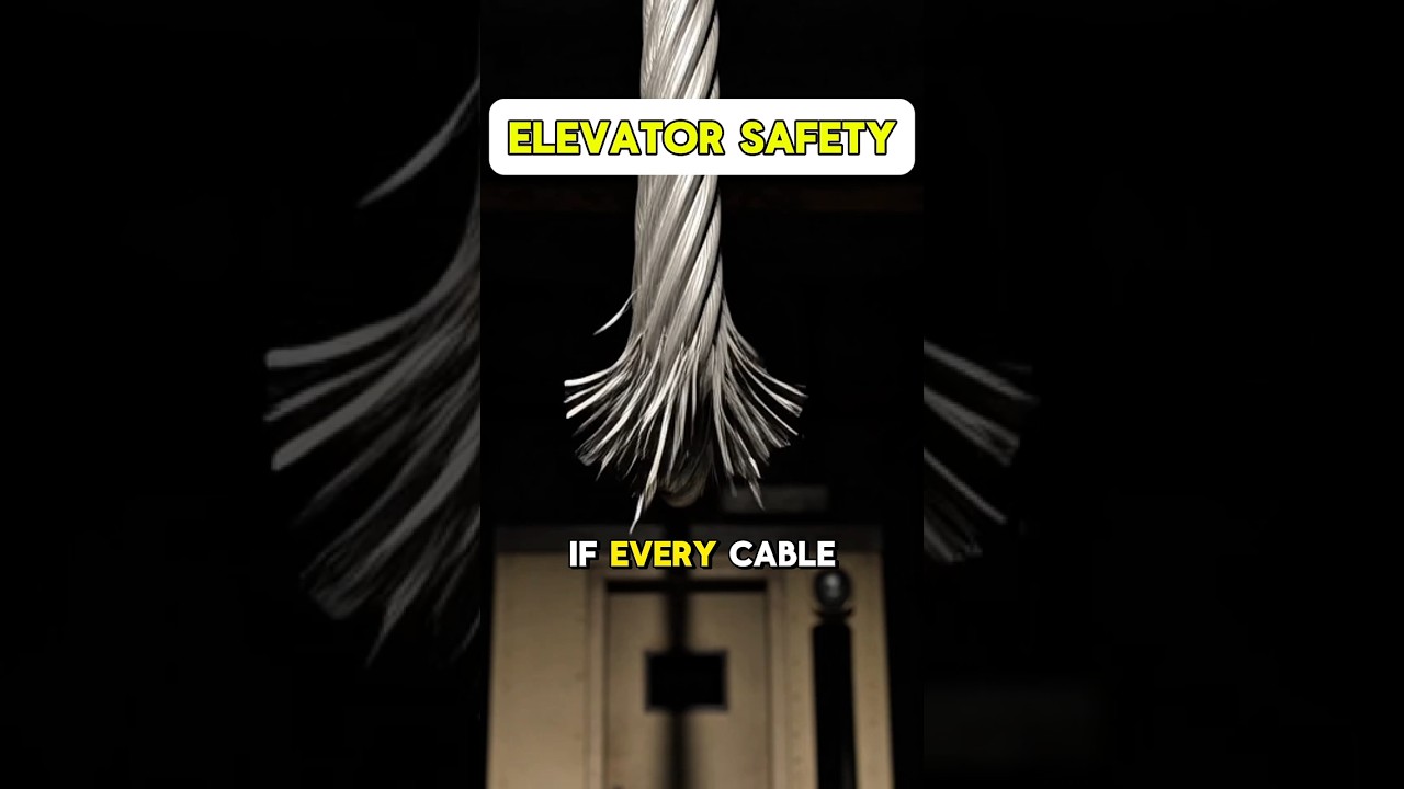
Elevators are equipped with an overspeed governor, a separate pulley system that continuously monitors the elevator's falling speed. If the speed exceeds a predetermined safety limit, the governor's arms trigger a mechanical switch that activates safety wedges, which are forced into the guide rails. This creates friction that stops the elevator. The braking force is proportional to the passenger's weight—heavier passengers cause the wedges to grip the rails more tightly, providing stronger braking. This system ensures that even if all elevator cables snap simultaneously, the elevator will not fall to the ground.
Click to watch →
Elevator Systems Fundamentals: Dover B.E.S.T. Training Video
27.2K
Governors and safeties are used on traction and roped hydraulic elevators but not on non-roped hydraulic elevators. A governor senses overspeed conditions and trips an electrical switch to remove power from the motor and brake, setting the brake to stop the car. If overspeed continues during descent, the governor trips a mechanical switch locking the governor rope to the safety lever, activating safeties mounted on the safety plank under the car. When safeties engage, jaws grip the rails to bring the car to a controlled stop. Safeties can only be used with T-rails, which is why less expensive Omega rails may be used on non-roped hydraulic applications.
Click to watch →
Deep Dive
Regulatory standards and codes for elevator safety, such as ASME A17.1 in North America or EN 81-20/50 in Europe.

15-54 Elevator and Escalator Standards and Codes
415
Currently, two organizations are certified by ANSI to accredit elevator inspectors: the Elevator Industry Preservation Fund (through the International Union of Elevator Constructors) and NAIA (National Association of Elevator Safety Authorities International). Both must follow QI1 requirements including 10 continuing education hours annually, original examination, and possession of all necessary code books. ASME develops A17.1, one of the oldest and most respected technical standards in the United States, comparable to the National Electrical Code. ASME serves as the parent organization that develops foundational elevator standards while A77 handles specific technical standards for technicians, representing a vertical integration of elevator technology standards.
Click to watch →

ITEEA - Cables de Acero para Ascensores - A cargo de IPH SAICF
5.4K
La norma ASME A17.1 establece reglas de seguridad para ascensores, incluyendo factores mínimos de relación de sobre (diámetro de polea/diámetro de cable) y factores de servicio. A diferencia de la norma europea, la norma americana permite menores relaciones de sobre y admite el uso de cables de menor diámetro en ciertos casos.
Click to watch →
Normativa ascensori-UNI EN 81-20 e UNI EN 81-50 (video 1 di 2)
2K
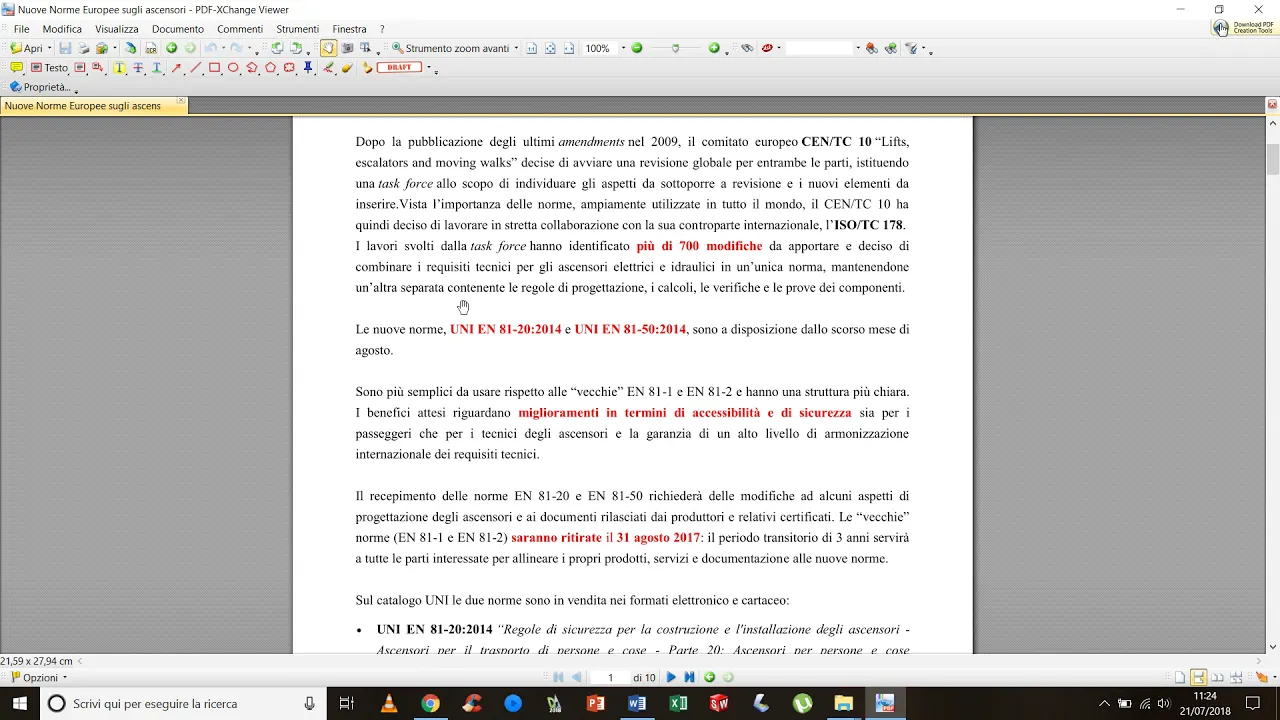
The European standards EN 81-20 and EN 81-50, published in August 2014 and effective from August 31, 2017, replaced the older EN 81-1 and EN 81-2 standards, establishing comprehensive safety requirements for new passenger and goods elevators, including rules for accessibility, safety, and component verification procedures.
Click to watch →

ระบบลิฟท์และบันไดเลื่อน
1.7K
Elevator safety in Thailand is governed by the Building Control Act (B.C.A.) with five versions (2522, 2535, 2541, 2550, 2558), ensuring urban order, building safety, fire prevention, and public health. Buildings are classified by area and height: residential/small (≤500 sqm, ≤15m), large (>1,000 sqm, 15-23m), extra-large (≥10,000 sqm), and high-rise (≥23m). Firefighting elevators require 630 kg minimum capacity, stop at every floor, and travel within 1 minute. Standards include Thai, American (ANSI A17.1, ASME), European (EN 81, EN 115), Singapore (SLS), and UK (CIBSE) standards. Components include elevator shaft with car and counterweight (balancing 50% of load), machine room with motor and controls, and elevator pit. Safety systems include speed governors limiting speed to 125% of design speed, safety gears locking the car to guide rails, limit switches with final limit switches as backup, and buffer systems (oil or spring) in the pit. Door interlocks prevent movement when doors are open.
Click to watch →

HOA Complained About My Porch Steps, So I Installed an Escalator!
10.4K
ASME A17.1 is the safety code for elevators and escalators, written for commercial buildings. Key requirements include: power requirements (often three-phase power), structural requirements (escalators weigh tons and need reinforced pits and heavy-duty support), weatherproofing (outdoor installation requires specialized components, drainage, and heating elements), and safety features (sensors, emergency stops, skirt guards, comb plates). The code assumes indoor commercial environments, not suburban residential porches.
Click to watch →
Deep Dive
Procedures for periodic maintenance, calibration, and safety testing (e.g., category tests and governor pull-through force tests).
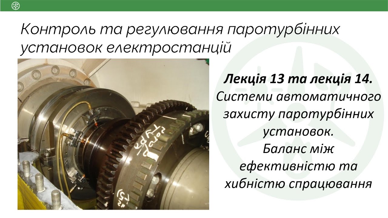
Лекція 13, 14. Системи автоматичного захисту турбін. Баланс між ефективністю та хибністю спрацювання
177
This section details safety governor testing and maintenance procedures. Safety governors require periodic testing to ensure proper operation. Testing is performed by adding oil to the safety governor's chamber, which increases the effective mass of the ring and lowers the trip threshold. This allows testing at lower frequencies (e.g., 3100 rpm instead of 3300 rpm). The complete chain is verified: sensor detection, signal transmission, solenoid operation, and stop valve closure. Testing should be done during operation, especially after long shutdowns, typically before synchronization.
Click to watch →
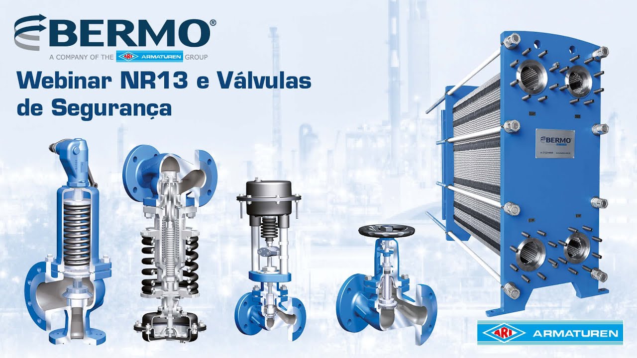
NR13 e Válvulas de Segurança | Aula Bermo - ARI Armaturen
2K
Safety valves require periodic inspection combined with internal and external vessel examinations: (1) 12 months for Category A and B boilers; (2) 15 months for Category C boilers; (3) 24 months for Category A boilers with annual pressure testing. The valve must undergo accumulation test, functional test, and opening test. Online testing is not permitted for annual inspection per NR13 - valves must be disassembled, inspected, and calibrated on a proper maintenance bench.
Click to watch →

How To Do Pull Force Test
2.3K
Before conducting pull tests, the testing machine must be calibrated. Calibration requirements include: (1) Third-party calibration must be valid with a sticker showing the calibration date (e.g., 26/11/2024), (2) Daily morning calibration must be performed before use, (3) The responsible person must be identified and the SF board must be displayed.
Click to watch →

Virtual Lunch & Learn: Safety Categories
4K
Safety Category 2 requires the safety function to be checked at machine startup and periodically by the control system. If a fault is detected, a safe state must be initiated or a warning provided. ISO 13849 assumes 100 tests per interaction, meaning if a guard door opens once per shift, it must be tested 100 times per shift. This ensures loss of safety function is detected between checking intervals. Safety monitoring relays constantly monitor inputs and use normally closed contacts to test output safety ratings, providing diagnostic coverage when contacts weld.
Click to watch →
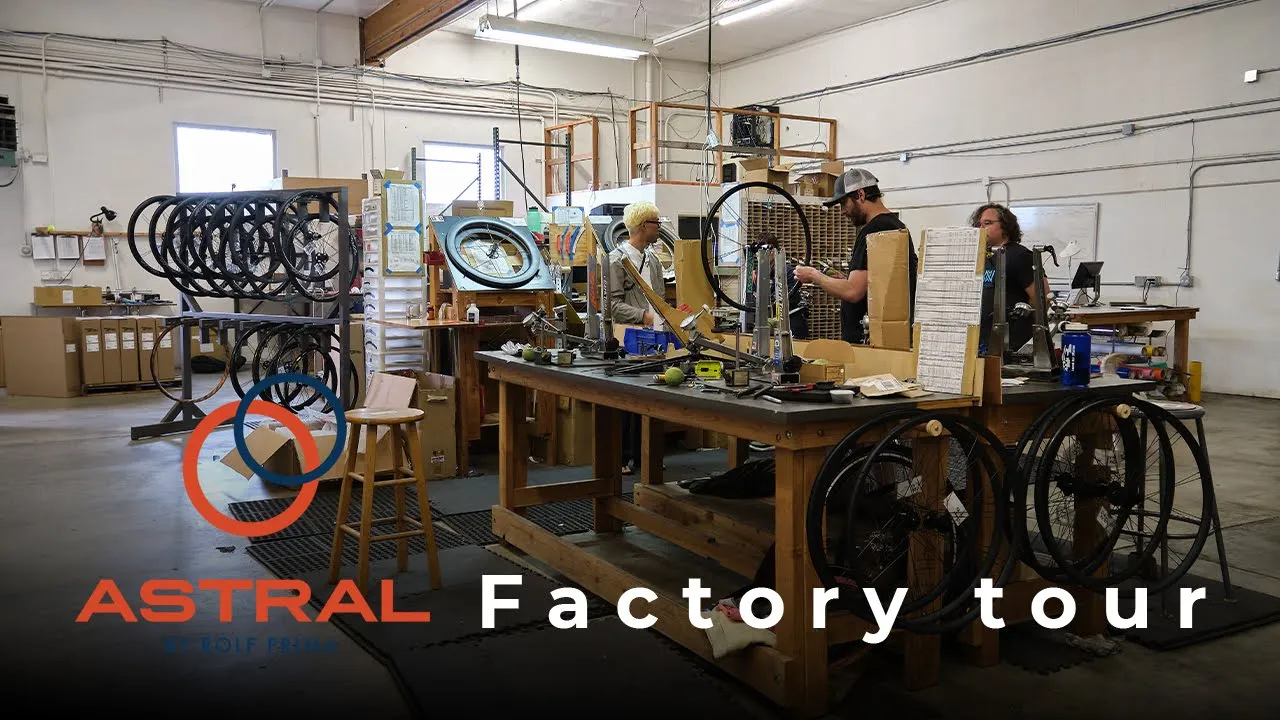
【Factory Tour】ASTRAL CYCLING/Rolf prima
9K
Spoke pull-through testing measures how much force is required to pull a spoke out of the rim. The machine pushes the hub down until spokes begin to pull through. This test measures the rim's ability to hold spokes under stress. The deflection point indicates the rim's strength and durability.
Click to watch →
Deep Dive
The evolution toward Machine-Room-Less (MRL) elevator safety designs and electronic governor systems (PESSRAL).

Poudre Fire Authority Department Elevator Rescue Class
18K
Three main elevator types exist: Traction elevators are cable-driven with traction machines, cables, counterweights, overspeed governors, and controllers. Machine rooms are typically in penthouses above the hoistway. Hydraulic elevators use pistons powered by hydraulic fluid, with machine rooms near the hoistway (first floor or basement). MRL (Machine Roomless) elevators have components contained within the hoistway except for the Controller, which is located adjacent to the motor near the top floor. MRL elevators are cheaper, easier to maintain, and more condensed than hydraulic elevators, making them the predominant choice for new installations. Motors can be mounted on sidewalls, head beams, or in pits, requiring rescuers to adapt their approach.
Click to watch →
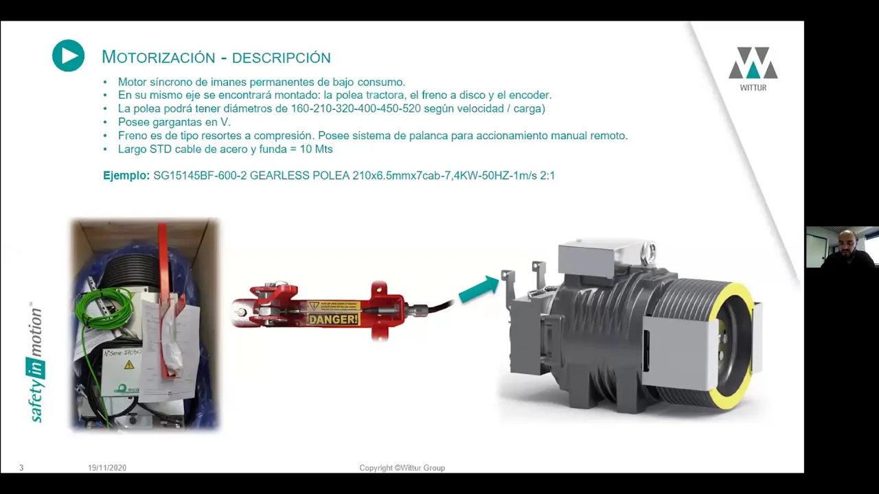
ITEEA - Ascensores sin sala de máquinas - A cargo de WITTUR S.A.
6K
MRL (Machine Room Less) elevators eliminate traditional machine rooms, liberating construction space for other uses. Key features include bidirectional parachute safety systems, silent operation without reducers, and automated emergency rescue. Technical specifications range from 450-2500 kg capacity, 1-2 m/s speed, and 60m travel distance. The suspension uses 21 cables with deflection pulleys on both counterweight and cabin chassis. The motorization employs synchronous permanent magnet motors with low consumption, compact size, and high torque. Pulley diameters range from 360-520 mm with cable diameters of 160-210 mm. The brake system uses spring-compression brakes with two independent plates and manual disconnection levers. Electrical connections include variable frequency inverters, thermal protectors, and micro switches for brake monitoring. The brake regulation is factory-set with high precision. MRL elevators use absolute encoders (Heidenheim SN 13 13) providing continuous rotational reference without zero-point detection. Cable installation requires alignment with longitudinal markings to prevent torsion damage. The UCM (Unintended Card Moment) system detects unintended cabin movement and triggers the speed governor. The emergency power system (UPS) activates during power cuts, moving the elevator to the nearest floor and opening doors for passenger evacuation. MRL elevators are delivered in modular packaging organized by installation sequence, with guide supports and hardware pre-organized for each floor level. Guide rails have specific upper section lengths (approximately 1500mm) with pre-drilled holes. Installation can start from top to bottom or bottom to top, with calculations determining exact positions.
Click to watch →
![[English] NEXIEZ-MRL -Machine-Room-Less Elevator- [Mitsubishi Official Video]](https://i.ytimg.com/vi/H8lpMYCz3aU/sddefault.jpg)
[English] NEXIEZ-MRL -Machine-Room-Less Elevator- [Mitsubishi Official Video]
8.6K
Machine-room-less (MRL) elevators eliminate the need for a separate machine room by integrating the motor and control systems directly into the hoistway, featuring energy-efficient regenerative converters that return braking energy to the building's electrical grid, destination-based dispatch systems that optimize traffic flow by assigning passengers to specific cars based on their destinations, and advanced safety systems including multi-beam door sensors, signal-type safety sensors, and 3D Hall motion detectors for enhanced passenger protection during emergencies such as power failures, fires, or earthquakes.
Click to watch →

TK EVOLUTION MRL Traction Elevator at Manezh Square Exhibition Center in Downtown Moscow, Russia
291
The Thyssenkrupp EVOLUTION MRL (Machine Room-Less) traction elevator at Manezh Square Exhibition Center in Moscow demonstrates modern elevator technology with a 1350kg capacity for 18 persons, featuring safety mechanisms like brakes and door locking systems, and operates at 1.0 m/s speed across 5 floors including basement levels.
Click to watch →

MRL Elevator Lift Shaft in running action
134.5K
This video demonstrates an MRL (Machine Room Less) elevator system in operation, showing the hoist motor, governor, Zenodine Zillbeg drive unit, brake chopper, and controller box working together; it illustrates how the counterweight moves downward as the lift car ascends, balancing the weight of the car and passengers to reduce energy consumption.
Click to watch →
Safety measures
Rope break action
Emergency brake
Stopping motion
Safety measures
0:00- 1
Additional measures prevent potential cab falls.
- 2
Systems are designed to ensure passenger safety.
Electronic Safety Systems (PESSRAL) and Machine-Room-Less (MRL) Technology
While traditional mechanical rope governors and safety gears in dedicated machine rooms have long been the industry standard, modern elevator engineering is increasingly shifting toward Programmable Electronic Systems in Safety Related Applications for Lifts (PESSRAL) and Machine-Room-Less (MRL) configurations. Traditional mechanical systems rely on physical governor ropes, tension weights, and centrifugal force, which require regular maintenance, are prone to mechanical wear, and demand significant structural space. In contrast, PESSRAL replaces mechanical governors with electronic sensors, absolute encoders, and software-driven safety controllers to monitor speed and position. This shift eliminates bulky ropes and pulleys, reduces mechanical failure points, and allows for real-time diagnostics. Furthermore, modern architecture increasingly favors MRL designs to maximize usable building space and lower construction costs, challenging the necessity of traditional machine-room-dependent safety layouts.
Basic mechanical principles of traction elevators, including the roles of the hoistway, car frame, guide rails, and counterweight.
The physical concept of centrifugal force and how rotational speed can be used to trigger mechanical mechanisms.
The fundamentals of electrical safety circuits (safety loops) and how mechanical switches interrupt power to industrial machinery.
In-depth analysis of safety gear types (instantaneous vs. progressive) and how they physically grip the guide rails during an overspeed event.
Regulatory standards and codes for elevator safety, such as ASME A17.1 in North America or EN 81-20/50 in Europe.
Procedures for periodic maintenance, calibration, and safety testing (e.g., category tests and governor pull-through force tests).
The evolution toward Machine-Room-Less (MRL) elevator safety designs and electronic governor systems (PESSRAL).
7K views0likes0:45@東芝エレベータ株式会社Original Release: 2017-10-10
other measures are also used to prevent the possibility of cab Falls [Music] even if a rope were to be severed once the cab reached or exceeded a certain speed a rote linked to a governor would be pulled engaging the wedge on the emergency stop device on the cab [Music] this is pressed against the guide rail bringing the cab to a stop [Music] you
Up Next
1:58
The Invention That Made Skyscrapers Possible | History of Building Design
@OUPAcademic
32.8K views•2015-08-28

12:54
Triumph of Orthodoxy Icon: Byzantine Art & History Explained
@BenCallan
2.1K views•2024-08-06

9:49
FastAPI vs Flask vs Django: Choosing the Right Python Web Framework
@TechWithTim
302.5K views•2024-05-26

1:42
Game of Thrones Opening Credits: A Cinematic Analysis
@gameofthrones
46.3M views•2011-04-18
Related Study Plans & Knowledge Roadmaps
Structured learning paths in General & Interdisciplinary Studies
general-studies
Elevator Engineering: History, Physics & Cities
01From Hoists to Safety Brakes: The Dawn of Vertical Lift
02Hydraulic vs. Traction: The Engineering Physics of Elevators
03Modern Speed, Safety, and Algorithms
+ 2 more learning modules
12h5 modules
Explore Roadmap
general-studies
Rubber: Material Science, History & Geopolitics
01Origins of Natural Rubber & Mesoamerican History
02The Chemistry of Natural Rubber & Vulcanization
03The Geopolitics of the Rubber Boom & Colonization
+ 2 more learning modules
12h5 modules
Explore Roadmap
general-studies
Containerization: Evolution, Logistics & Trade
01Ancient Trade & Bulk Cargo: Amphorae to Barrels
02The Industrial Revolution & Cardboard Packaging
03The Containerization Revolution: Malcom McLean
+ 2 more learning modules
12h5 modules
Explore Roadmap
general-studies
Textile Tech: Evolution, Labor & Global Impact
01Pre-Industrial Textiles: Handloom & Cottage Industry
02Mechanization: The Spinning Jenny to the Power Loom
03The Factory System & Global Labor Transformation
+ 2 more learning modules
10h5 modules
Explore Roadmap