


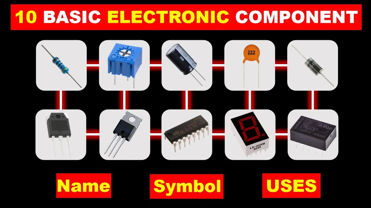









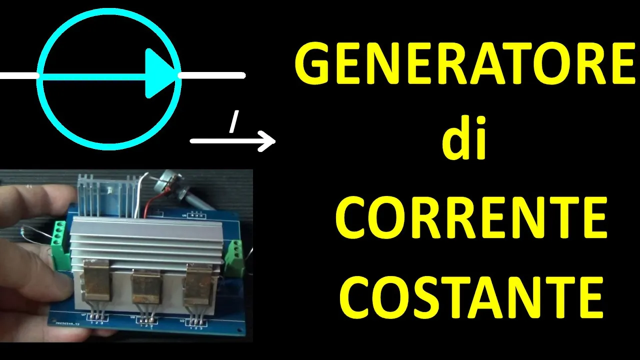











This video demonstrates how to build a simple adjustable lab power supply using the LM317/LM350 voltage regulator, covering component selection, circuit calculations, and testing procedures. The key principles include understanding the regulator's 1.25V reference voltage for adjustable output, calculating resistor values for desired voltage ranges, designing input/output filtering with appropriate capacitor values, and managing heat dissipation through proper heat sink selection. The LM317 can deliver up to 1.5A with a maximum dropout voltage of 2.5V, making it suitable for adjustable power supplies in the 1.25V to 37V range. The design requires a transformer with sufficient VA rating, bridge rectification, input and output capacitors, and a potentiometer for voltage adjustment, with the heat sink size determined by the power dissipation calculation (P = (Vin - Vout) × Iload).
Building an LM317 Lab Power Supply: Part 1 - Design and Calculations
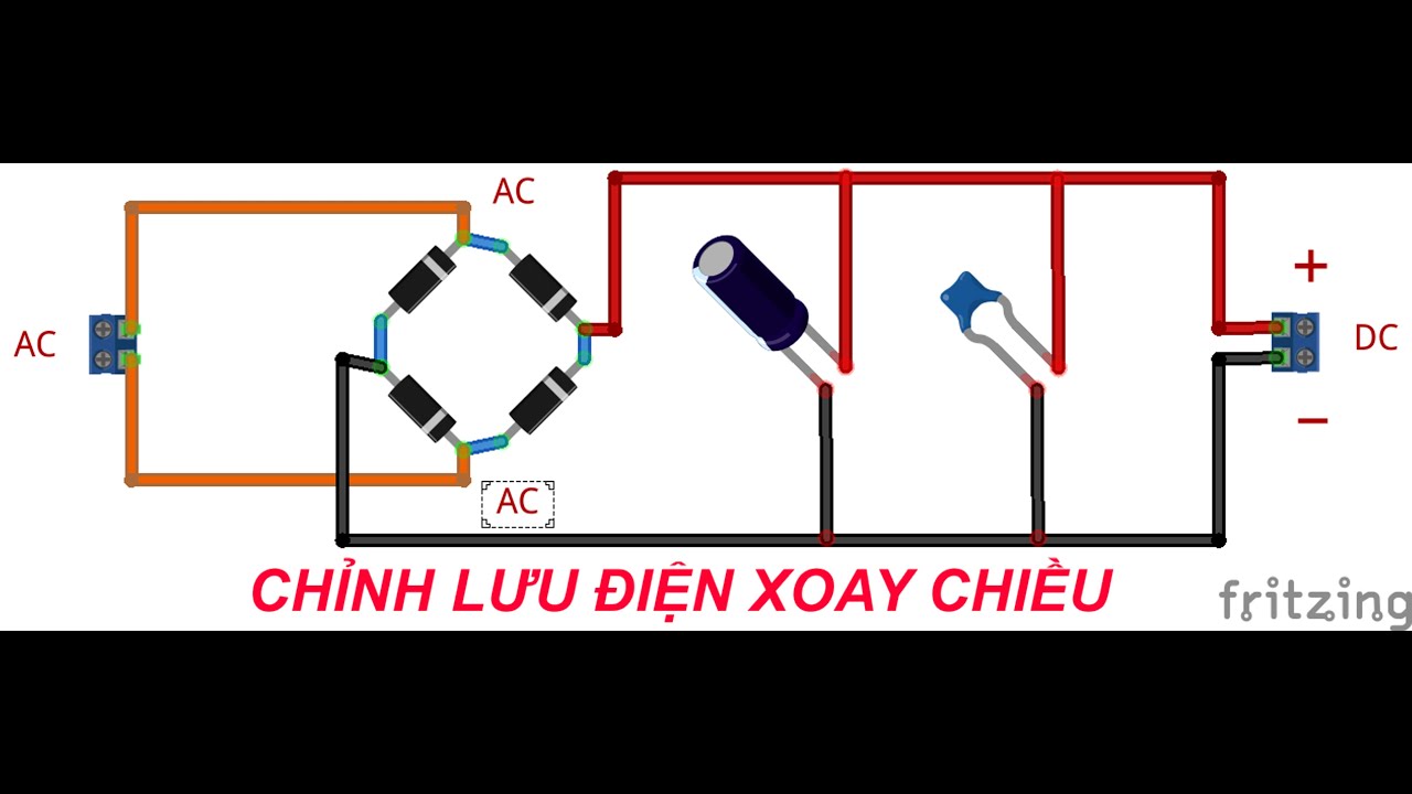
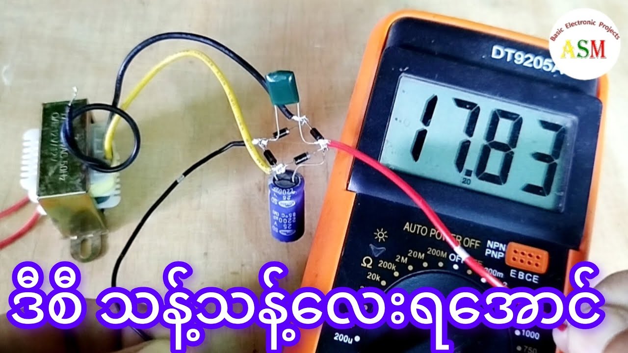
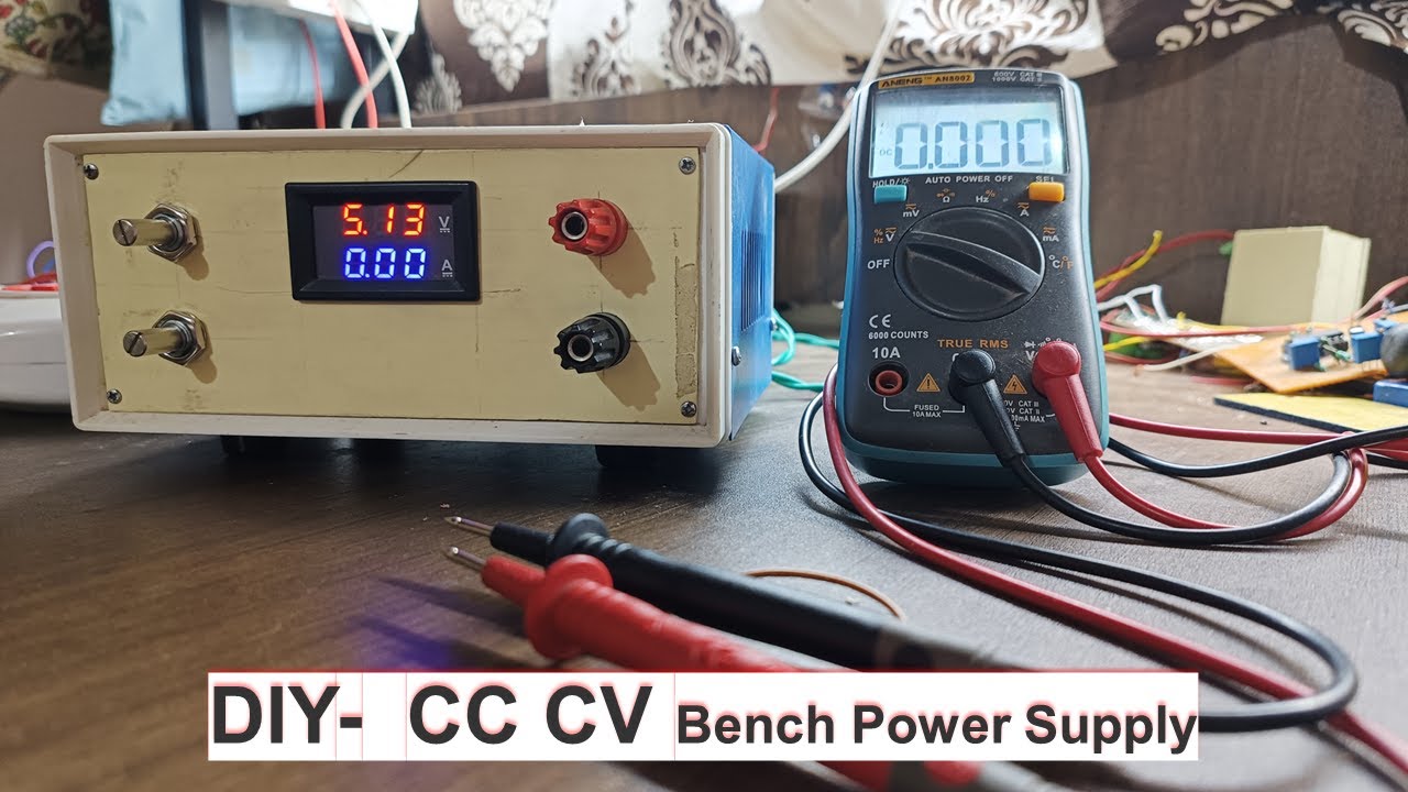
Added:hello and welcome to e projects today we will go through how to make a simple adjustable power supply out of the LM 317 voltage regulator or in this case I use the LM 350 but it's almost the same and the calculations will be the same the power supply will be capable of delivering voltage between 1.25 and in this case 28 volts but the regulator can go all the way to 37 volts so if you have a Transformer that's outputting that much then you can easily make that happen so let's start by taking this power supply apart so you can see how I have built mine you can make up your own mind how you want to do yours [Music] T so the most important things we have in here is the Transformer and the voltage regulator but of course we need a bit more we have the mains power coming in down the bottom there then go into the uh onoff switch then goes to the fuse goes to the Transformer then from the Transformer secondary windings we have this tap select switch so we can select between 12 and 24 wats this gives us 14 and 28 wats in DC we then have the wire going to this main board down here with uh some rectifying diodes to make a bridge rectifier we have two input filter caps we have the rest of the circuitry for the regulator and we have the regulator itself mounted on this heat sink with a little fan on it then we need a potentiometer to control the voltage this is a tin Turn part i h recommend that but you can use a single turn if you want and we have a voltmeter to measure the voltage and we have our finding posts down here and we then have a a load switch to turn the output on and off and I also have a 12v regulator for the fan a little diode and the capacitor over here just kind of botched in there but there was a secondary winding that I didn't use on this Transformer so I use that for the fan so I don't introduce any unwanted noise to the rest of the power supply SE and let's just take a look at the back and see what we got here then we just have the main input again the power switch fuse and the tab select switch on the transform you can see the back side of the voltmeter and the part and the onof switch for the output so when I first designed this I had the regulator mounted on the bolt down here but the heat sing on it and there that didn't last very long it broke off eventually and so I It Up by just gluing it to the bottom of the case down there that seems to hold so to get to how to build one of these I have the schematic in board layout and everything on my website so you can download that there's also a text version of how you build one of these if you prefer that but you will probably prefer to just watch the video so let's find the data seat for the regulator and see what we can come up with we might as well take a look at what made me choose the lm350 in the first place this was the first power supply that I built and uh when I made it I had very little knowledge about Electronics so I searched around the internet for some simple voltage regulators and I found the lm317 but uh I noticed that it's only capable of 1.5 as and uh I went to my local component distributor and I asked him if he had something similar to the lm317 that will give me about 3 or five as so he had the lm350 that was almost as cheap as the lm317 and he had this uh LM 338 it's in a T3 package and uh this was much more expensive so I didn't buy that one at the time I chose the lm350 there's not very much of a difference between the lm317 and the LM 350 except that the lm350 can uh deliver free amps and it's only capable of going to 33 Watts where the lm317 can go to 37 volts also the uh input output differential voltage versus the output current is better on the lm350 so if I have an input of 30 volts and an output of 5 volts then I can maybe deliver we can take a look at the uh Curves in a minute but if this one can deliver 1 a this might only deliver 300 milliamps or there about I don't know but that was something I didn't know about at the time so I had a little experience with the the regulator shutting down and all kind of weird stuff so that's something you learn when you play around with these things without knowing what you're really dealing with but I managed to make a power supply out of this regulator and that's why I chose it to uh to be the one I will talk about in this video because it is very easy to use so if we take a look at the lm317 data sheet we can get an overview of what we need to make it run as I said the output voltage range is from 1.2 to 37 watts and it's capable of delivering in excess of 1.5 amps the L load regulation is better than.1% and the it's a floating regulator so you can use Min in series if you want that and also it's it's not about [Music] the the input to ground voltage it's about the input differential voltage so you can have a maybe an input voltage of 50 volts as long as your output voltage stays within 37 volts of that it has compl complete series of protections this is very important for us because we don't want the power supply to blow up if we accidentally short the output or something like that it has a thermal shutdown and a safe operating area control and The Regulators are monolitic integrated circuits in to220 and so on packages intended for us as positive adjustable Mage regulators and here's something important the nominal output voltage is selected by the means of only a resistive divider making the device exceptionally easy to use and eliminating the stocking of many fixed Regulators but uh in this case we just want to use it as a a variable Supply so so we have skipped on to a page three of the data sheet and here's an example of a typical application this is a basic adjustable regulator and that that is exactly what we want but we're going to add a little extra circuitry some input and output caps and some diodes and a capacitor from the uh uh from the adjust pin to ground so the way this regulator works is that it's it have an internal reference of 1.25 volts it will have this reference across the adjust pin and the output so by putting a fixed resistor across there and then a variable resistor to ground we can change kind of the feedback voltage to the regulator and it will rise the output until the input uh matches the reference so in this electrical characteristics table for the regulator we find all sorts of parameters that give us some space and information on the regulator there's some important things in here like a minimum load current and the reference voltage we talked about earlier from up here this minimum load current is one of the things that affect this resistor R1 which we have to choose later on when we are designing the circuit we want to use because if this resistor is too high then there's not enough current going to going to Gra round through this resistor and then the output cannot go all the way down to 1.25 Vols if there's nothing connected to the output of course and we of course have to look at the uh right table because this is only for the LM 1117 and 217 so if we take the next pce we can see that actually the minimum load current has changed from 5 mamps Max to 10 milliamp Max so we designed it for 5 milliamps and it might not work on the LM 317 because it it can need as much as 10 MMS and if we take a look at this graph I talked about earlier about the output current versus input output differential voltage you can see that uh we can only have an input output differential voltage of about 15 17 volts if you want the full 1.5 amp output if we go above that then the output current will drop off so this is one thing that's better in the lm350 regulator if you want an output of 1.5 amps then we can use the the whole uh voltage range and if you want the 3M output that it's capable of it will be around 15 watts in difference between the input and output but another thing is to get the heat away from the regulator if we start to dissipate huge amounts of watts in it it will uh go into a thermal shutdown anyway because it's overheating and another thing to care about is the Dropout voltage of the regulator the input have to be a few volts over the output voltage at any time for the regulator to stay in its regulation so if we uh do not meet this requirement then the output will start to drop when we uh put a certain amount of current through the regulator and we don't want that so so this Dropout voltage is affected both by the temperature and the output current so as we can see here the the lower graph is for 20 mamps and this upper one is for 1.5 amps the xaxis is the temperature and the y- AIS is the uh voltage drop or the Dropout voltage so if we kind of take the highest possible Dropout voltage for the regulator that is 2.5 volts so if we keep our input 2.5 volts over our output we should not uh get any problem with the regulator dropping out of its regulation so we'll keep that in mind when we design the circuit so another thing is this uh power supply is not going to be very uh stable on the output if you draw a huge amount of current out of it or it will it will stabilize but if you uh set it to 10 volts and then you hook up a 1.5 aamp load then the output voltage will will start to drift a little until the uh temperature has settled inside and this is something to do with the the reference voltage versus The Junction temperature and all the other components in the regulator and we will measure that when we start doing some tests of the power supply this will still be usable for most Electronics Works anyway so but if you need some very very fine and stable output voltages maybe you shouldn't use the LM 317 so to calculate the output voltage from this regulator we given this formula here that's uh we out equals the voltage reference Time 1 + R2 R1 plus I adjust * R2 and they are saying that the device is designed to minimize the term I adjust micro 100 microamps Max and they're saying that in most cases we can just delete this and just use this and the since we are probably using five or 1% resistors anyway then this gets much slower than than our other tolerances so in this case we'll just forget about this iust it doesn't really matter that much as said we will be using the typical application circuit from this data seed and they state that the performance may be improved by adding capacitance as follows and an input bypass capacitor of.1 microf an adjustment terminal to ground capacitor of 10 microf to improve the Ripple rejection of about 15 DB a one microf tlum or 25 microf aluminum electrolytic capacitor to the output to improve the trenant response and in additional to external capacitors it's good practice to add protection diodes as shown in figure five and we will also do that so as a funny little detail we'll take a look at figure five again as they claim will show the protection D I can't seem to find any but I found it in in figure eight instead so we'll take a look at that one so we have this diode of the up the top here that will protect against shorts on the input so the output capacitor will not discharge back through the regulator and this one will protect against the this capacitor on the adjustment pin so that cannot discharge through the regulator in a DAT sheet from another manufacturer they are claiming that these diodes are not necessary if the output current and output voltage is not in excess of some limit but we will put them in there anyway so this circuit is in fact the thing that we will be building we'll need to add something on the input here and we'll need to add something on the output as well since we're using a Transformer to deliver the current to this regulator we will need to rectify the AC so we get a DC signal and we'll need some input capacitors to reduce the Ripple on the input on the output we'll need an load switch we'll need some binding post and we will need a voltmeter so we can uh read the output voltage we could also add a m meter if we want that so we can read the output current as well and just to sum up we will have to take a look at the Transformer the rectification the input caps the two divider resistors to set set the output voltage we'll need a heat sink and we'll need some uh panel meters to show us the voltage and current outputs for the rest of the circuitry we will just use what they have specified in the data sheet you can find the exact schematic I have been using on my website e- projects.com and it's all the way on the bottom of the page when you select the simple adjustable power supply so this is basically just what's in the data seat but I have added the bridge rectifier the input caps the output caps and all the rest of the circuitry I have also labeled all these components so they match the component designators on the PCB itself you can also find the board layouts the component overview some drawings of the Transformer wiring and uh the board I have been making and again I have mounted the uh the regulator and the heat tank on the board and it's just hold in place by the solar joints on the regulator and that's not how you're going to do it but we will get back to that and I have a much better idea of what you can uh do just to have the heating on the board if you have a a need for that and I have done some experiments with the uh input fill cap values and we'll also do that in this video there's some uh values for the potentiometer and the R1 resistor uh versus different output voltages there something about heat TS how to calculate the size and values of the heat sink and uh most important there the materials list and a nice picture and yes it took quite some time to get it to 3.30 on the multimeter now that we know what we need to look at we can start to do some calculations and if we start with the Transformer all the way at the input side we can then slowly move across to finish at the output let's start by taking a look at the Transformer because this is where we get our power to the regulator there's uh many different types of Transformers but you can use pretty much anything you want there's these standard types of Transformers I think they call the H frame or something like that and this is basically the same as this one this is just a PCB Mount version and then there's uh these toot Transformers now which type of Transformer you get does not really matter but the important thing is that it is rated for your Mains voltage and here in Denmark we have 230 volts at 50 HZ so this Transformer will be capable of that you can see the secondary winding is 2 * 12 Vols at 3.3 amps AC this means that we can either use these as two separate 12vt supplies or we can make 124 Vol or we can make a combination of those so we can get a a lower voltage when we using a lower voltage on our power supply so we don't have to dissipate as much heat in the heat tank but we'll get to that in a minute it is of course important that you don't exceed this maximum current rating on the Transformer because then the Transformer will get hot and it can actually melt and uh short out and start a small fire you don't want that to happen now this Transformer does only have one secondary winding and one primary winding and the way you can tell which is which will be that the since this is a Step Down Transformer and I know this is rated for the main voltage then the fine wire on this side will be the the primary winding in the course f wire on this side will be the secondary winding because the voltage will drop equally to the ratio of the turn so if you have a this is a a 24 volt transformer so if we had 2 40 volts going in and 24 volts going out it would be 1/10th of the turns on this side than on this side here if you don't have a confidence in working with Main's electricity you probably shouldn't use a Transformer you can then use one of those uh AC to DC brake adapters that come with uh laptops or printers or something like that instead of the Transformer you'll then just wire those across the plus and minus DC on the board instead of the AC and uh that's these two notes here so you're you're just skipping the uh the rectifying part of the circuit but you can do that when you're using a a DC input if you're going to buy a transform it's a good idea to get one with a split secondary winding like I showed you with the toal Transformer before and uh it can be either one of the these two types here now this typ thing is just something I came up with but you can get a Transformer where the winding is just split with a and only a single wire is coming out in the middle of the Transformer here or you can get one with two separate secondary windings and this type is the most common one but these two also exist now which one of these you get doesn't matter because we are going to make it into one of these Anyway by connecting the two Center conductors here and we're going to connect them in a way so we can select between 12 or 24 volts if that's the case with a a toggle switch so the way we can do this is very simple we have U one end of one of the secondary windings going directly to the board and the other end of that winding combined with the the first end of the next winding will go to one position on the switch one of the on positions and uh the other end of the second winding will go to the other on position and then the common position on the uh the switch will go directly to the board so when you flick the switch you will just either use that part or the whole transform but you can also do some more advanced stuff where you can put multiple windings in par and stuff like that but we won't go into that because there's risk of getting unbalanced load and you can melt down your transform so that's not a good thing in this case my Transformer was still capable of delivering all the current I needed with the one of the windings so I didn't bother to do that but uh you can look that up if you want to make yours like that and on the primary side of the Transformer you always want to add a fuse and you probably want to have a switch as well so you can cut the power to the whole thing but if your Transformer doesn't have a split secondary winding then you don't have to worry about all of this you will just have the the two conductors going to the B and you can also add a fuse on the secondary side as well if you want that so when you have your Transformer in place you'll have a signal that looks like this from the output of the Transformer and uh this is an AC signal and of course we cannot make it ecy Power Supply out of that so we use a bridge rectifier to get all the the negative voltage kind of flip over to the positive side and we will build up a little experiment to experiment with the capacitors we need to flatten this out because this doesn't make a very good power supply either because we have all these bumps that go all the way down to zero Watts I have hooked up the Transformer to the Main's electricity and I have put in the the uh rectifying diodes and uh we have the regulator here don't mind all the rest of this that is just for something else I am working on so I put a fuse in the series with the Transformer just so if anything should touch each other then it won't uh destroy the Transformer or melt down any wires or anything let's first take a look at what the signal looks like when we uh measure it directly on the secondary winding of the transform so this is a a 24v RMS Transformer and we can see we're getting a 28.7 vol RMS AC out of this and uh when we load this with the 3.3 amp I'm pretty sure that would be almost 24 wats but they uh they do drop in voltage when you load them so that's something to take into account and we can also see that the peak to Peak voltage is 80.8 volts so uh it's not something you want to play around with if you're not careful so let's see what happens when we look at the signal on the other side of the bridge rectifier so we'll turn off the power here we will move the ground lead and the probe to the other side of the rectifier we'll try to turn on the scope again you can see that's way out of range here so there's something wrong here it we'll just uh put a little bit of a load on there so I've just put a a 12K resistor across the the ground and the positive and now we can see that the uh waveform have been flipped so that the negative now is also a positive signal we can see that our Peak to Peak voltage is now a little under half of what it was before this is because there's a little bit of a voltage Dr over the the rectifying diodes but that's nothing to worry about really it's about6 Volts for each diode so we have two of those in series and we will get a a 1.2 Vol drop so if we just change the time base a little here we will be able to see the differ it makes difference it will make when we put in this uh filter cap we'll just turn off the power again so we don't show out anything and uh now we can see what difference that makes now can see that 100 microfat capacitor made a huge difference in the uh amount of reel we got here it's it's almost disappeared and if we change this to AC coupling and uh change the lot per division you can we can Center this and you can see that that's about a 320 molt Riel with that um 12 KO resistor in there that would be perfectly fine for power supply but uh but the problem is that when we put a huge load on this then the uh 100 microf capacitor will just be discharged to Z volts and then charged up again at the at the next uh Power Cycle so just by changing that resistor we will see that this uh Ripple will get much worse so I'll try to find something with a little lower value so we can try to put that in there so now with a 4.7 KO ohm resistant there we already getting 720 Ms of ribon and uh since we that will give us uh 8 milliamps of load and we'll need to be able to to draw well over 1.5 amps out of this so we will need a lot more of input capacitance and there's uh formulas to calculate the value of the capacitor we need so if we say we want a maximum of 2 volts ripple at a full load of 3 amps on our power supply then we can uh calculate the capacitance needed to obtain that and that formula is not very difficult at all uh assuming that we have um our capacitors charged to the maximum voltage each time uh we can use this formula that the um Ripple voltage or the difference in the voltage equals the amps that you're pulling out of them divided by the frequency of the charge of the capacitors this is the Main's voltage times two because we are rectifying it through the bridge Rectify so we get all the negative Peaks flipped up so we have the we have the double of the frequency and this is times the capacity of the capacitance but since we don't know the capacitance but we know the the uh Ripple voltage that we want to obtain then we can uh flip these around so we can calculate the uh capacity from the drawn current divided by the frequency times the uh rer voltage so to to get a 2vt ripple voltage we will need a 15 mad capacitor or 15,000 microfarad and you can easily get a 10 Millar and 4.7 mad so that's probably what I would use if I had to design this today and when I built this I used 6.8 mad so that's uh just over half this so I could expect 4 WS of in my power supply and this Ripper voltage is important when we have to calculate the uh resistive divider for setting the output voltage if we uh set the output voltage above what uh our voltage at the the minimum voltage of the capacitor so that's the voltage in minus the Ripple voltage if we set the output above that then the uh output will start to have the Riel as well when we uh draw enough current and we don't want that so we have to set the output voltage below this uh level if we could say so the only problem with these uh 10 m capacitors is that they are quite large and and I don't think you will be able to fit these in the board I have designed so if you want to use this large capacitors you have to to do your own board but I used one of these uh 4.7 m capacitors and 2.2 m in my P and it seems to work fine but you'll get a little more Ribble current you could maybe fit two of these in there but I'm not sure and I don't know if you will be able to get a 10 m that's kind of have a a smaller footprint and will be a little higher but you can also work with the with the L the 6.9 very so if we wanted to use the lm350 voltage regulator we had a problem here because our input voltage will be too high even if we subtract the minimum output voltage of uh 1.25 volts we still have an input output differential voltage of about 36 volts and that's uh 3 volts above the um specified value but again the lm317 will be capable of 37 volts input output differential voltage now I can also subtract the 1.25 volts so this will be just suitable for the LM 31 in I have now connected the regulator to the rest of the circuit and added a potentiometer and the resistor and we will go into the calculations of these in uh in just a minute but first I want to show you what will happen if you set the output voltage higher than the input voltage minus the Ripper voltage we are now at 4 volts at the output and we can uh turn the potentiometer to rise the output voltage you can see when we hit the uh about first 34 volts it's starting to to get to get into the the Ripple and with these uh resistor and part values I have chosen I still have about 1/8 of a turn on the potentiometer so we will need to find [Music] a value for the resistant the potentiometer so that we will not get into this ripple at the top of the uh voltage range so to calculate the resistor divider values we will need to know the maximum output voltage from the regulator and we know that the output voltage from the Transformer is 24 volts RMS and that is uh 33.943398 volts at the peak of the waveform and uh to calculate the maximum output voltage we take this voltage and we uh subtract the voltage drop over the bridge rectifier and we have a 2vt ripple on the input filter caps and then we have the 2.5 Vol uh Dropout voltage of the regulator and so that that gives us 28.24 volts as our maximum output voltage and this will be at a full load of 3 amps so if you're using the lm317 regulator you can maybe get a little more out of it because you only need to calculate with the 1.5 amps instead of 3M so this will only be about 1 watt instead of 2 Watts if you're using the same input for the capacitor so now that we know our maximum output voltage we can calculate these two resistor values here and with the resistors I have in there now the potentiometer and the fixed resistor we are able to get an output voltage of 36.66% [Music] 28. 24 Vols this is way too high so we need to change one of these two resistors and the potentiometer is not that easy to change so we will change the fixed resistor to a value that will match the desired output voltage and we can find a new value for R1 by using this equation here which gives us uh I was using a 4.7 KO ohm potentiometer but it measured 5,100 ohms so I used that value instead and we will not be able to find a 236.50 ohm in series and we'll be out by 1.2 ohms and then that'll be just fine so I changed the resistor R1 to the uh 235 5 ohms and it was a little bit oh it was reading 28.9 volt so so I changed the 15 Ohm resistor to a 18 ohm and uh now let's see where we are going to have our maximum voltage and now it's 28.4 volts on the scope at least it could be a couple of couple of hundred Ms out but that's not far away from our 28.24 volts now we should be able to load this with the fre amps and uh the output should stay clean and uh free of any Ripple but there's something else that we can uh take a look at if we wind the pot all the way down we might just be able to see here on the scope that it will start to kind of oscillate down the bottom here like that so if we if we change the scope to AC coupling uh adjust the time base we can now see that we have this uh oscillating signal at uh around 6 MHz and that's about uh 1.4 Vols Peak to Peak so this will not make for a really good power supply but you might remember that we did not put any uh output capacitors on this regulator so I'm pretty sure if we uh put the uh 25 microfarad capacit that they recommend in the data seat we will see this oscillation disappear and I'm about to connect the capacitor right now but if we uh turn the the vertical scale all the way down you can see we still have these spikes and the frequency is measuring 100 HZ so that's the double of the main Main's frequency or it's the same frequency as the uh the signal we have after the uh Bridge rectifier so my guess is that this is uh the Ripper from the input of the regulator getting through to the output now there's not much load on this regulator but uh as you might remember I did put a uh 4.7 KO Ohm resistor across the input filter capacitor so it act as a load when we measured the uh the rectified signal so let me try to remove that 4.7 KO Ohm resistor and you can see this ramping has gotten lower in amplitude and there's also a figure in the data seat specifying how much of the input RI will get through to the output and this uh now we have about 20 mws of Ripple and I guess that's about normal so this is the line Trent response for the lm350 voltage regulator and you can see if we have an input voltage change of 1 volts we will have an output voltage deviation of about 1.25 volts with a uh 1 microf and a 10 microf capacitor on the uh output and the adjust pin and I put a 25 22 microfarad on both so we should see a little better than this and it's and of course this is for the lm350 it's and we're using the lm317 so it could be slightly different but it's not far what we're seeing from the scope here and as we saw when we measured the Ripple on the input we had about uh just under 800 Ms of Ripple with the resistant place so this would be another reason to have a high amount of input capacitance as we increase the load we will have more Ripple on the input filter caps and that will result in more Ripple on the output so the more input capacitance the better so the next thing to calculate on the list here is the heat sink and I also have an example of that on my website so we can take a look at that so the power dissipated in the regulator will be equal to the difference in the input and the output voltage times the current so if you have an example of 24 volts in and the lowest setting of 1.25 volts out that's a different of difference of 22.75 volts and you times that with the current and you get 34 one to five Watts so you will need a heat sink that has low enough FAL resistance so that the regulator will not overheat but 34 wats is a lot of power and uh that's another reason why we need to have a tap select switch on the Transformer so that when we're working with the uh lower voltages we can select an input voltage that is half of the maximum so will not dissipate as much in the heat sink so if we lower this V in to 12 volts then our difference will only be 10.75 volts and we'll have just over 16 watts to dissipate instead of 34 and by adding a fan to the heat tank we can lower the Firma resistance by a great amount so that's a good idea to include a fan in your design the Firma resistance of a heat sink tells how many degrees it will rise in temperature if you put one wat into it and of course a smaller heat sink will heat up faster than a a larger heat sink and of course by blowing air through the heat sink that will cool it down and and therefore the thermal resistance will be lower usually the data seat for the heat sink tells what the f resistance is both uh with passive Cooling and with active cooling where the active cooling will be where you blow air through it with a fan and uh for this power supply you will probably need a heat sink about this size or maybe a little larger if you are using a fan if you don't use a fan then you will you'll need a larger heat sink if you're going to draw a a lot of current over a long period of time and the only thing left on the list is the panel meter in my power supply I used one of these uh cheap up meters from eBay and uh they seem to work very well they have an uh adjustment part on the back so you can trim them for the best accuracy uh there's only one deal place in these meters and they can go to 99.9 volts but they are accurate to that uh decimal so that one decimal place over the entire range so I'm quite happy with these and if I remember correctly they cost under $4 so that's nothing really but you can of course use one of these old school analog meters this is is kind of a uh a blank 500 microamp a meter but can also be turned into a volmeter but you can of course also make your own VA and aater by using a microcontrol and using the built-in ADC I'm working on this little board where I have a pig 16 F 616 reading the voltage directly with the ADC and reading the current through a current sense amplifier and you might have seen this Bard in my PCB manufacturer tutorial and I will also make a video of this project when it's finished and uh the schematic and Bo layouts will be available on my website once L on and test it of course but the idea with this was that it should be uh small enough to fit on the back side of one of these 16x2 LCD displays you can also get one of these four half digigit voltmeter chips that will put out a uh binary coded decimal signal and you can then decode that with a BCD to seven segment or LCD decoder and then you can use an LCD or seven segment displays and uh just remember with these digital panel meters that you'll need one that has the separate sense wire because when you're going down to 1.25 volts you don't want your display to dim out I think this will work from here we have it it will work from 4.5 to 30 volts and it can measure a DC from 0 to 99.9 Watts so we have to power this from the non-regulated side of the power supply so right after the input filter caps that they go way higher than 30 volts in some situations so what I have done is uh since this uses very little current I have just uh put a Cena diode in series with the Positive lead so that when uh the Taps switch is on the high then it will not go over the 30 volts and when it's on the low it will still be over 4.5 and that way we don't uh fry the back end out of this meter
Up Next

SMD Heatsink Design: Thermal Vias & PCB Case Cooling
@EEVblog
100.3K views•2015-05-15

Ultrasonic Transducers: Resonant Frequency Measurement and Horn Design
@imajeenyus42
229.9K views•2017-02-22

Polymer Environmental Degradation: Mechanisms & Stabilization
@iit
1.8K views•2012-07-10

How a Student's Question Saved a NYC Skyscraper from Collapse
@veritasium
22.8M views•2025-04-26
Related Study Plans & Knowledge Roadmaps
Structured learning paths in Engineering