In wind turbine applications, modifying blade design to be more aerodynamic significantly increases electrical voltage output; flattening and refining blade shapes can boost voltage from approximately 2 volts to over 4 volts, demonstrating that optimized blade geometry improves energy conversion efficiency in small-scale wind power systems.
Measuring DC Motor Voltage Output for Wind Turbine Battery Charging
Added:Deep Dive
Basic principles of electromagnetism, specifically how a DC motor can function in reverse as an electrical generator.
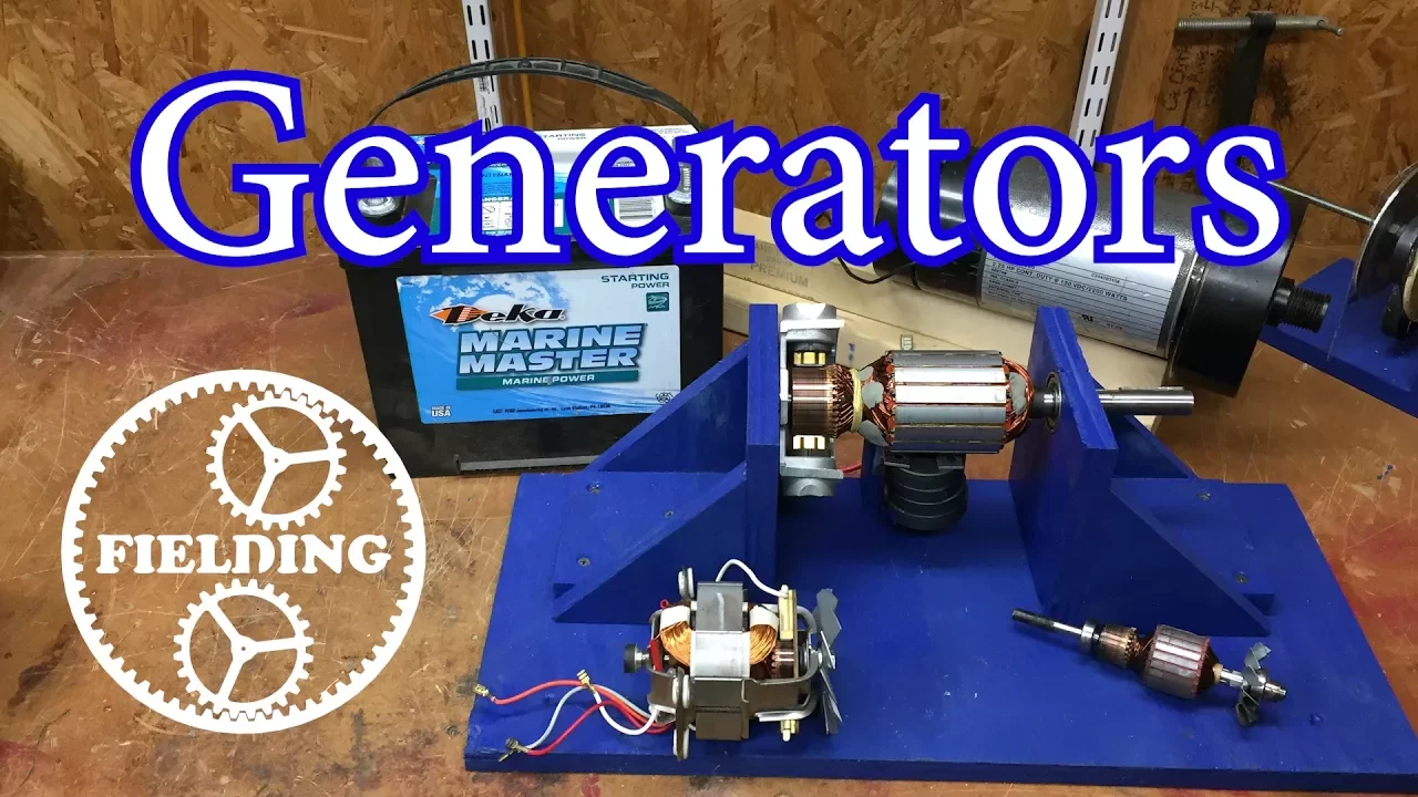
How Motors Work for Beginners (Episode 2): The Generator and Universal Motor: 033
557.9K
A DC motor can function as a generator when its shaft is spun mechanically. When the rotor wires move through a magnetic field, electromagnetic induction causes current to flow in the wires, which then passes through the commutator. This principle demonstrates the reversibility of electric motors and generators.
Click to watch →
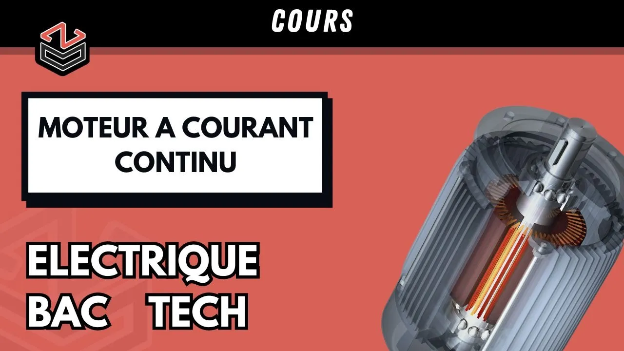
.ÉLECTRIQUE ⚡ (Part 3) : Principe de fonctionnement d'un M.C.C
72.7K
This video explains the fundamental principles of DC motors and generators. A conductor placed in a magnetic field experiences a force (Lorentz force) that causes motion. The same machine can function as either a motor (converting electrical energy to mechanical energy) or a generator (converting mechanical energy to electrical energy), making it reversible. To reverse the direction of rotation in a DC motor, one must reverse the direction of the current. The video demonstrates these principles through practical examples and explanations of electromagnetic interactions.
Click to watch →

MOTORS -The Secret Life of Components, a series of guides for makers and designers 11
164.7K
DC motors can function as generators when spun mechanically. Connecting two motors together, spinning one with a drill causes the other to rotate. This principle underlies most household electricity generation, where fossil fuels create steam to power turbines that drive generators similar to ordinary DC motors. The intimate connection between magnetism and electricity enables this bidirectional energy conversion.
Click to watch →

Lecture - 27 D C Motors
160.5K
The DC motor is structurally identical to the DC generator but operates in reverse energy flow direction. While the generator converts mechanical energy to electrical energy (rotated by prime mover, producing voltage), the motor converts electrical energy to mechanical energy (applied voltage causes rotation). Both share the same gyrator relationship: T = KI and E = Kω, but with reversed input-output ports. The same machine can function as either device depending on energy flow direction.
Click to watch →
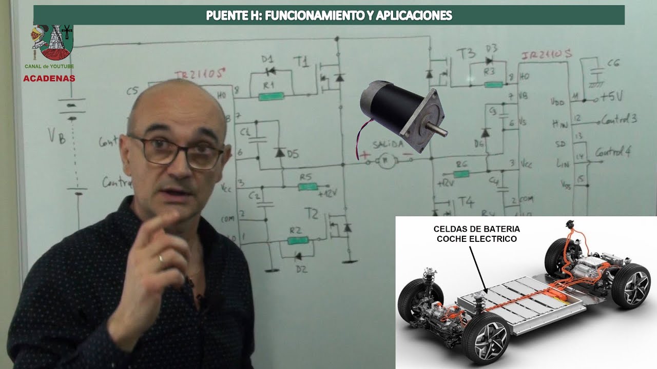
Puente H: Funcionamiento y aplicaciones (Clase 119)
58.1K
A DC motor can function as a generator when mechanical energy is applied to rotate it. When the motor is spun, the magnetic field induces a voltage (back EMF) that generates current. The current flows in the opposite direction to the motor operation, creating a braking torque. This principle is fundamental to regenerative braking systems. The motor's inertia and magnetic field cause it to generate electricity when mechanically driven, converting kinetic energy back to electrical energy.
Click to watch →
Deep Dive
Fundamental electrical concepts such as voltage, current, resistance, and how to safely use a multimeter to measure them.

How To Use A Multimeter: The VERY Basics!
341.5K
A multimeter is an essential electronic tool for measuring four fundamental electrical quantities: continuity (whether two points are electrically connected), resistance (how much a material opposes current flow, measured in ohms), voltage (electrical potential difference, measured in volts), and current (flow of electric charge, measured in amperes). To use a multimeter safely and effectively, always connect the black lead to the COM jack and the red lead to the appropriate measurement jack (Ω for resistance/continuity, V for voltage, A for current). For continuity and resistance measurements, the circuit must be disconnected from power; for voltage and current measurements, the circuit must be powered on. When measuring current, break the circuit and insert the multimeter in series, then immediately remove the leads from the current jacks afterward to prevent damaging the fuse. Understanding these basic principles allows beginners to diagnose circuits, verify component connections, and troubleshoot electrical problems systematically.
Click to watch →

How to read & use analogue/digital multimeters
11.5K
This section introduces the three fundamental electrical concepts: voltage (potential energy difference per charge, measured in volts), current (flow of electrons, measured in amps), and resistance (opposition to current flow, measured in ohms). It explains how to measure each: voltage requires parallel connection across a component, current requires series connection by breaking the circuit, and resistance requires removing the component from the circuit. The section also covers multimeter probe connections, with the black cable always connecting to the COM port and the red cable to the appropriate measurement terminal.
Click to watch →

MULTÍMETRO: DO BÁSICO AO AVANÇADO NA PRÁTICA
1.4M
Current measurement requires connecting the multimeter in series with the circuit, allowing current to flow through the device. This creates a vulnerable state where excessive current can damage equipment. Always return the multimeter to voltage mode after current measurements. Resistance is the opposition to current flow, with every component having internal resistance. Always measure resistance on a de-energized component because the multimeter provides its own power source. Ohm's Law (V=IR) explains the relationship between voltage, current, and resistance: low resistance causes high current, while high resistance (oxidation, poor contact) reduces current.
Click to watch →

ELECTRÓNICA ELEMENTAL, CLASE 1, MAGNITUDES ELÉCTRICAS BÁSICAS , MULTÍMETRO Y MEDICIONES.
1.5K
A multimeter (also called polímetro, metro, or digital multimeter) measures three fundamental electrical magnitudes: voltage, current, and resistance. Voltage is the force that pushes electrons to move, also called 'tensión' or 'diferencia de potencial'. Electrons move from areas of higher concentration to areas with fewer electrons, creating current. There are two types of voltage: DC (fixed polarity) and AC (changing polarity). Electric current is the flow of electrons through a closed circuit, measured in amperes. Circuits are closed paths that allow current to flow. LEDs are semiconductor devices that convert electrical energy into light through electron movement. Semiconductors can emit visible or invisible light. Resistance opposes current flow, measured in ohms. To measure resistance, the circuit must be disconnected from power.
Click to watch →

How to Use Multimeter Readings for Electrical Troubleshooting (Webinar) | TPC Training
192.9K
A multimeter measures three fundamental electrical quantities: current (flow of electrons), voltage (potential difference between points), and resistance (opposition to current flow). Current can be observed through visible effects like lights illuminating or motors humming. Voltage requires comparing two distinct points rather than measuring a single location. Resistance is measured in ohms and determines whether current can flow through a component. Understanding these three parameters is essential for effective electrical troubleshooting.
Click to watch →
Deep Dive
The basics of battery chemistry and charging requirements, including nominal voltage thresholds for rechargeable cells like AA batteries.

Pilhas de 1,5 v usb e 1,2v recarregáveis bateria de 9v usb DAWEIKALA recarregável tipos e modelos
13.4K
This section covers the basic principles of rechargeable batteries and cells. It explains the different types available (AA, 9V, and stick cells), their physical characteristics, and charging requirements. The video demonstrates that rechargeable batteries require external chargers, with simple chargers taking 5-16 hours and intelligent chargers providing automatic detection and display. A key technical point is that rechargeable batteries have a nominal voltage of 1.2V, which is lower than standard 1.5V batteries, potentially causing compatibility issues with some electronic devices. The section also covers voltage measurements showing fully charged batteries at 1.29-1.35V and discharged batteries at around 0.5V.
Click to watch →
20 Amp Battery Charger with Computer Power Supply - 220v AC to 1.5v / 3v / 6v / 9v / 12v / 24v DC
1.9M
Different battery types require specific charging voltages. AA/AAA alkaline batteries (1.5V nominal) can be charged using a combination of +3.3V and +5V outputs (producing approximately 1.673V). The charging process is verified by monitoring voltage increase over time; if the measured voltage rises, the battery is receiving charge.
Click to watch →
Зарядное устройство для аккумуляторных батареек. Сколько заряжать аккумуляторные батарейки.
157.5K
Rechargeable batteries are primarily nickel-based (nickel-cadmium and nickel-metal hydride) or lithium-based (lithium-ion and lithium polymer). For nickel batteries, charging current should be 1/10th of capacity (e.g., 210 mA for 2100 mAh). Higher currents (400-1000 mA) charge faster but reduce lifespan. Simple charging devices ($3) require filling both slots, mixing incompatible battery types, capacities, or dates. Users must manually calculate charging time (capacity ÷ current) and monitor with timers to prevent overcharging, which causes reverse discharge and capacity loss.
Click to watch →

EEVblog #751 - How To Debunk A Product (The Batteriser)
368.9K
Products designed to work with both rechargeable and primary batteries must operate down to at least 1.1 volts per cell, which is the standard cut-off voltage for rechargeable batteries. This ensures that rechargeable batteries are not over-discharged, which would damage them. The Bizer's claim of 1.35V cut-off is incompatible with rechargeable battery requirements and represents a misunderstanding of battery management principles.
Click to watch →

QUÍMICA ENEM DIGITAL 2020! "As pilhas recarregáveis, bastante utilizadas atualmente, são formadas.."
4.4K
Rechargeable batteries function as galvanic cells during discharge (spontaneous process) and as electrolytic cells during charging (non-spontaneous process). To calculate the minimum voltage a charger must provide, determine the cell potential using standard reduction potentials: for Ni-Cd batteries, E°(Ni²⁺/Ni) = -0.230 V and E°(Cd²⁺/Cd) = -0.402 V. The minimum voltage required is the absolute difference between these potentials, which equals 0.172 V. This represents the minimum energy input needed to reverse the spontaneous discharge reaction.
Click to watch →
Deep Dive
Elementary aerodynamics, particularly how wind flow exerts force on a turbine blade to produce rotational torque.
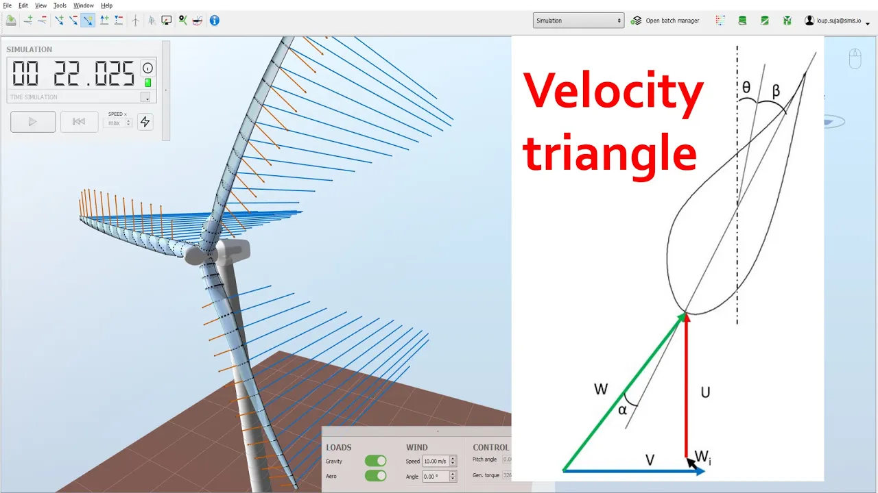
Wind turbine velocity triangle explained with ASHES - the wind turbine simulation software
70.4K
Wind turbine blades experience two primary aerodynamic forces: lift (perpendicular to relative velocity, 100-200x larger than drag) and drag (parallel to relative velocity). The total force combines these to create torque (tangential component causing rotation) and thrust (radial component pushing backward). Despite high lift-to-drag ratios, turbines produce more thrust than torque due to design constraints. This fundamental trade-off shapes modern turbine engineering, where optimizing blade geometry aims to maximize useful rotational torque while minimizing structural loads from excessive thrust.
Click to watch →
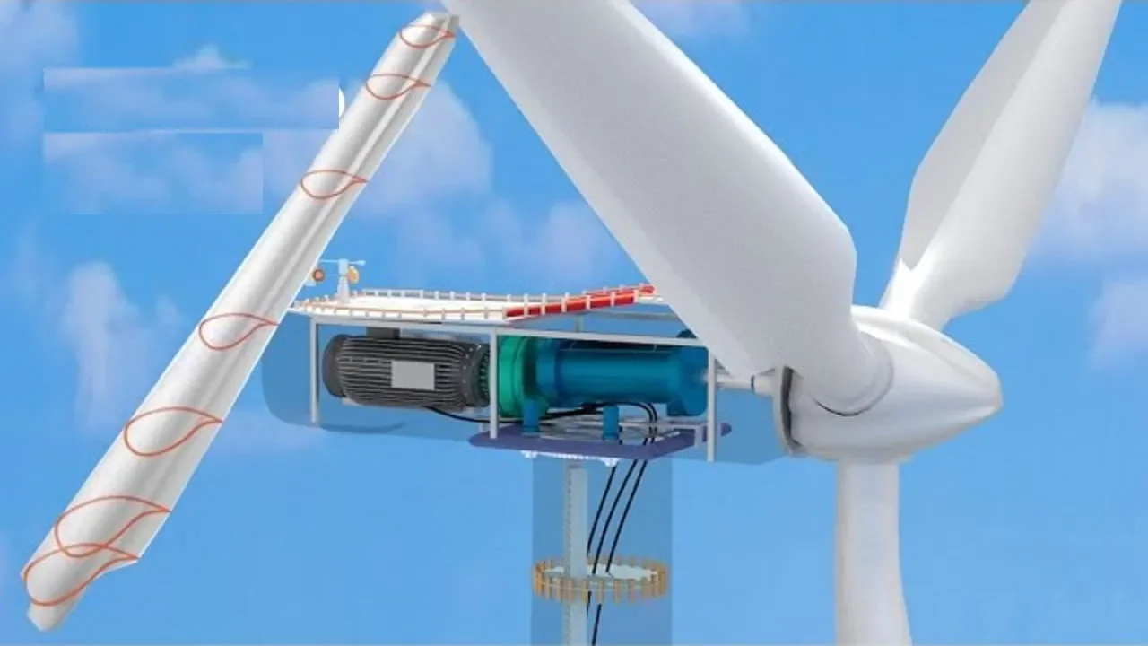
Como Funcionam As Turbinas Eólicas?
2.4M
Wind turbine blades are designed with multiple cross-sectional airfoil sections that vary in size and shape from root to tip. The aerodynamic technology causes the blade to rotate when wind flows over it, producing a lift force. This lift force is generated when fluid (wind) moves over the airfoil surface, creating the rotational motion that drives the turbine.
Click to watch →

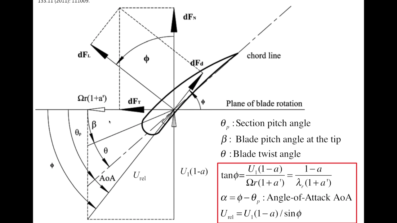
Blade Element Momentum Theory, Wind Turbine Aerodynamics Lecture 4
1.6K
This section covers the fundamental velocity relationships and force resolution in blade element analysis. Two tangential velocity components act on the blade: rotational velocity ΩR and tangential flow induction factor a' times ΩR, giving net tangential velocity (1 + a')ΩR. From velocity resolution, sinφ = [U∞(1 - a)]/W and cosφ = [(1 + a')ΩR]/W, where W is the resultant relative velocity. Lift L acts perpendicular to airflow while drag D opposes it. These forces resolve into: vertical direction Lcosφ + Dsinφ (contributing to actual force) and horizontal direction Lsinφ - Dcosφ (generating torque). Aerodynamic forces use lift and drag coefficients: ΔL = ½ρW²cCLΔR and ΔD = ½ρW²cCDΔR.
Click to watch →

14. Flow and forces around a wind turbine blade
121.6K
Wind turbine blades operate based on aerodynamic principles where the relative wind velocity creates lift and drag forces that drive rotor rotation; the velocity triangle combines the incoming wind velocity, rotational velocity (ωr), and induced velocities to calculate the flow angle, which determines the angle of attack for airfoil lift generation, enabling engineers to compute blade forces using standard airfoil data and optimize power extraction through the relationship between induction factors and tip speed ratio.
Click to watch →
Understanding Wind Turbines (09) - Aerodynamics 7
18.3K
This section develops the methodology for calculating forces on turbine blades. Lift force acts perpendicular to relative wind, while drag force acts parallel, forming a right angle. These forces project onto rotor plane axes to yield normal force (DF_N = DF_Lcosφ + DF_Dsinφ) for thrust and tangential force (DF_T = DF_Lsinφ - DF_Dcosφ) for torque. Lift and drag coefficients (C_L, C_D) are dimensionless parameters obtained from wind tunnel testing, defined as force per unit area divided by dynamic pressure (0.5ρu²). These coefficients depend on angle of attack and enable prediction of blade forces under various operating conditions.
Click to watch →
Prerequisite Knowledge
- Concept 01Basic principles of electromagnetism, specifically how a DC motor can function in reverse as an electrical generator.
- Concept 02Fundamental electrical concepts such as voltage, current, resistance, and how to safely use a multimeter to measure them.
- Concept 03The basics of battery chemistry and charging requirements, including nominal voltage thresholds for rechargeable cells like AA batteries.
- Concept 04Elementary aerodynamics, particularly how wind flow exerts force on a turbine blade to produce rotational torque.
Subsequent Learning
- Step 01Designing and implementing voltage regulation circuits, such as DC-to-DC boost converters, to stabilize fluctuating generator outputs.
- Step 02Understanding charge controller circuit design, including the use of blocking diodes to prevent battery discharge back into the motor.
- Step 03Exploring power optimization techniques like Maximum Power Point Tracking (MPPT) for micro-scale wind generation.
- Step 04Scaling up renewable energy storage systems, including battery management systems (BMS) for multi-cell packs.
Motor Test
Blade Boost
Motor Test
0:20Playing Section
- 1
Salvaged DC motor from printer tested for voltage output.
- 2
Aerodynamic blade shaping increased voltage from 1.5V to 1.73V.
- 3
Potential use for charging AA batteries in parallel.
Limitations of Brushed DC Motors and the Necessity of Electronic Power Conditioning
While using a micro brushed DC motor and relying on blade design to boost voltage is a popular educational project, it is highly inefficient for practical wind power generation. Brushed DC motors suffer from high internal resistance, friction, and brush wear, making them poor generators compared to brushless alternators. Furthermore, relying purely on aerodynamic blade design to match battery charging voltage (e.g., boosting from 2V to 4V) is unreliable due to fluctuating wind speeds. A standard engineering approach utilizes electronic power conditioning, such as step-up (boost) DC-to-DC converters or Maximum Power Point Tracking (MPPT) controllers. These electronics dynamically adjust the voltage and current to match the battery's charging profile, ensuring safe, efficient, and consistent power transfer regardless of wind variability, while preventing the battery from discharging back through the motor during low-wind conditions.
Deep Dive
Designing and implementing voltage regulation circuits, such as DC-to-DC boost converters, to stabilize fluctuating generator outputs.

Джоуль вор со стабилизацией напряжения
49.4K
A low-voltage DC-DC boost converter with voltage stabilization uses a blocking generator circuit with two bipolar transistors, a dual-winding transformer, and a Zener diode feedback system to convert low input voltage (0.7-1.6V) to a stable higher output voltage (e.g., 5V), suitable for powering small electronic loads like LEDs and microchips with maximum output current around 580mA.
Click to watch →

Como funciona o controle e a estabilização da tensão de saída num Conversor DC-DC | Vídeo 3/4
10.4K
DC-DC converters maintain stable output voltage through negative feedback control systems where a voltage divider samples the output and sends it to an error amplifier, which compares it against a reference voltage and adjusts the PWM signal to the MOSFET switch; the error amplifier uses a transistor configuration with a Zener diode reference (typically 2.4V) to precisely control the feedback signal, while an optocoupler provides electrical isolation between the primary and secondary circuits, ensuring the output voltage remains within 1-2% of the target value (e.g., 18.5V-19.5V for a 19V output).
Click to watch →
DC-DC Boost converter tutorial
758.9K
A boost converter is a DC-DC converter circuit that steps up voltage by storing energy in an inductor when a switch is closed and releasing it to the output when the switch opens, using pulse width modulation to regulate output voltage; the output voltage is determined by the duty cycle and can be calculated using specific formulas, though real-world designs require controller chips for proper regulation and include components like inductors, diodes, capacitors, and frequency compensation networks for stable operation.
Click to watch →
Pr#23 Convertidor elevador de voltaje | BOOST DC-DC converter
104.8K
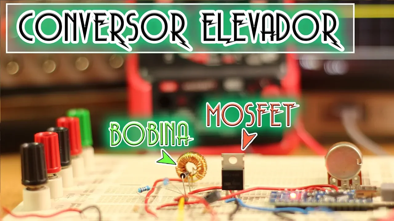
A boost DC-DC converter increases voltage from input to output using an inductor that stores energy when current flows through it and releases it as a higher voltage when the current is interrupted; the circuit requires a switch (typically a MOSFET), a diode to prevent reverse current, and a capacitor to smooth the output, with feedback control (via PWM duty cycle adjustment) maintaining stable output voltage despite changes in load or input voltage.
Click to watch →

Najdroższy głośnik BT na świecie ma poważny BŁĄD elektroniki !!
377.3K
DC-DC converters (switching regulators) efficiently convert input voltage to stable output voltages for electronic circuits. The video demonstrates analyzing a Texas Instruments TPS560200 converter that creates 3.3V from a 15V input. Key concepts include: (1) Enable pin function for controlling converter activation, (2) Soft start functionality using capacitors to prevent inrush current, (3) Voltage drop measurement to identify circuit resistance problems. The analysis shows how to identify the converter's enable pin and understand its role in the power delivery system.
Click to watch →
Deep Dive
Understanding charge controller circuit design, including the use of blocking diodes to prevent battery discharge back into the motor.

2038 Using Motor As Generators
31.4K
To prevent a battery from causing a motor generator to spin uncontrollably (which would discharge the battery), a diode must be connected in series with the positive output lead. The diode's anode connects toward the motor/generator, and the cathode connects toward the battery. This unidirectional flow prevents electricity from flowing back into the generator when it is not being driven, protecting both the battery and the generator.
Click to watch →
Inside a cheapo NiMh charger with schematic.
145.9K
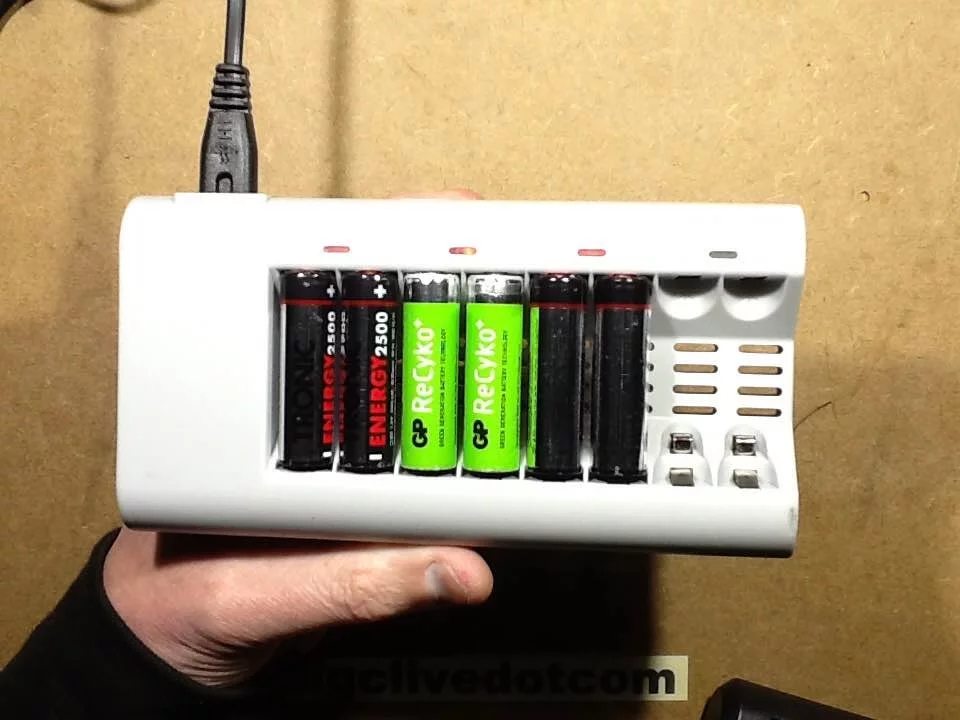
Protection diodes are placed in reverse parallel with MOSFETs to prevent reverse current flow when power is disconnected. This prevents battery discharge back into the charger circuitry when the unit is turned off, protecting both the batteries and the charger electronics.
Click to watch →

DC Rectifier/Charger Design Explained
713
Blocking diodes prevent reverse current flow from damaged chargers to healthy ones during faults, protecting control circuits from voltage feedback. They are essential for system stability and safety. Marketing terms like 'steering diodes' or 'auctioneering diodes' are misleading—natural voltage differences already determine current flow direction. Blocking diodes provide genuine functional value by isolating faulted equipment and maintaining control circuit integrity.
Click to watch →

Inside an Iso-tip rechargeable soldering iron. (And charger hack.)
212.9K
The charging circuit contains a single silicon diode in series with the transformer. The diode prevents reverse current flow and allows charging current to flow from the transformer to the battery. The presenter identifies this as a typical generic 1 amp diode. This simple design ensures that the battery is only charged when connected to the charger and prevents battery discharge through the charging circuit.
Click to watch →
Diode checking in PCB | Diode complete testing working principle in hindi | Diode explained in PCB
337.3K
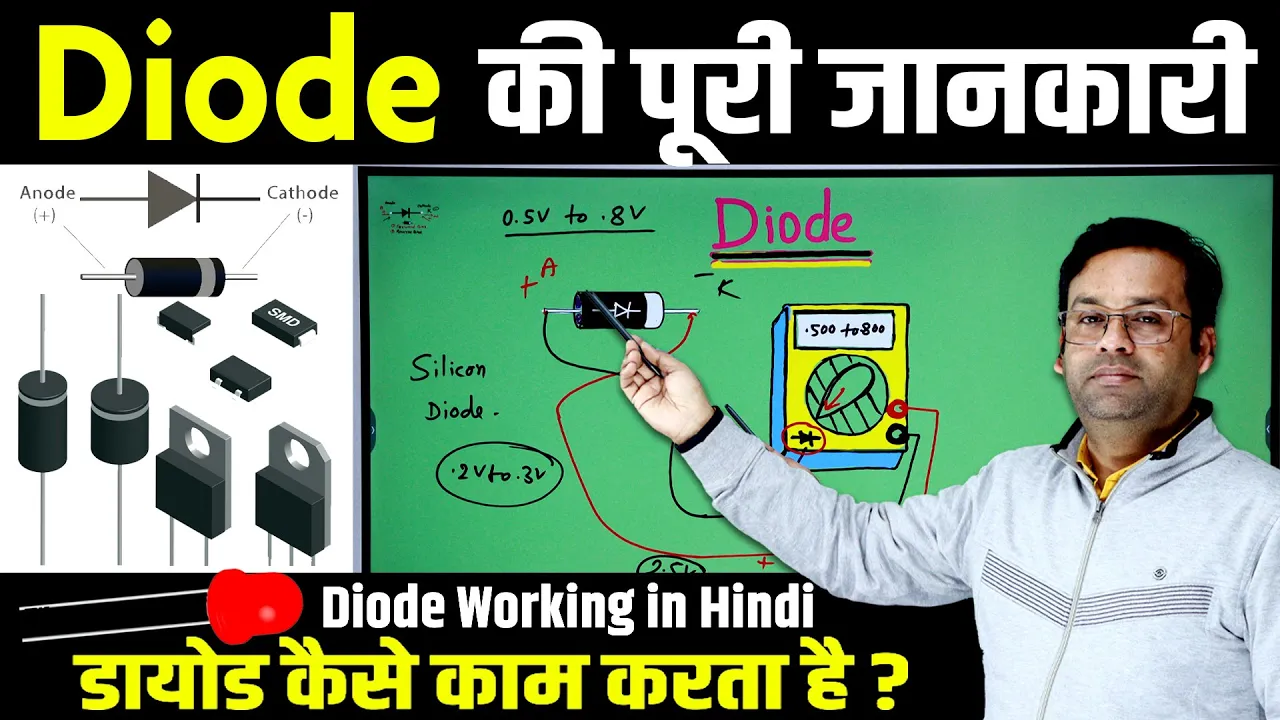
Diodes are used in battery chargers to prevent reverse current flow. When the charger is connected, current flows from the charger to the battery (forward direction). When the charger is disconnected, the diode prevents battery current from flowing back to the charger. This protects the battery and prevents the charger's indicator LED from glowing when power is off.
Click to watch →
Deep Dive
Exploring power optimization techniques like Maximum Power Point Tracking (MPPT) for micro-scale wind generation.
I tried to Power my Home with Wind Generators! (Worth it?)
1.6M
Maximum Power Point Tracking (MPPT) is an essential technology for optimizing wind power generation. The principle involves finding the optimal balance between current draw and generator speed - if too much current is drawn, the generator slows down and produces less power; if no current is drawn, no power is generated. An MPPT controller continuously monitors voltage and current to maintain operation at the maximum power point. In testing, a 12V/400W MPPT controller was found to work effectively but required generator voltages above 15V to function optimally, which may not be achievable under typical low-wind conditions.
Click to watch →
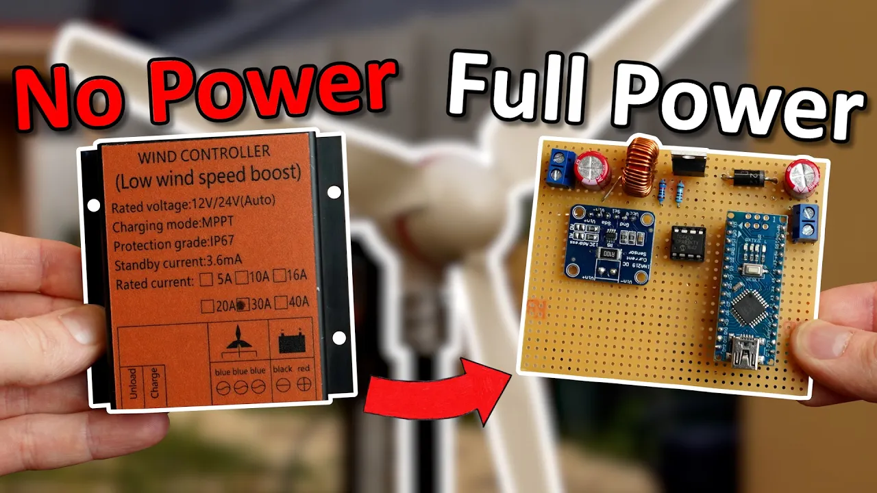
My Wind Generator Was Useless....Until NOW! (MPPT)
438.7K
MPPT is a technique used to extract maximum power from variable energy sources like solar panels and wind generators. Unlike batteries which maintain constant voltage, these renewable energy sources have a characteristic voltage-current curve where maximum power occurs at a specific operating point (the peak of the power hill). When environmental conditions change (less sun, lower temperature, less wind), this maximum power point moves along the curve. A tracker continuously follows this moving point to ensure optimal power extraction.
Click to watch →
Testing A Real Hydro Generator, Missouri Wind & Solar Freedom 1600 PMG
313.5K
Maximum Power Point Tracking (MPPT) is an electronic technique used in solar charge controllers and wind turbine systems to ensure that the generator or photovoltaic array operates at its peak efficiency regardless of changing conditions. Unlike a fixed load connection, MPPT devices continuously vary the electrical load presented to the generator to find and maintain the maximum power point. This is necessary because the optimal load resistance for maximum power output changes with generator speed and other environmental factors. Without MPPT, connecting a generator to a fixed load may result in suboptimal power extraction, as demonstrated when using a water heater resistor (12 ohms) versus a heating element wire (1.5 ohms) produced significantly different power outputs from the same generator.
Click to watch →

1826 What Is MPPT And PWM And What To Do With A DIY Wind Turbine
34.8K
MPPT is an advanced charge control method that tracks the maximum power point on the battery's voltage-current curve to optimize energy harvesting. Unlike PWM which follows battery voltage, MPPT continuously senses both voltage and current to find the optimal operating point. This requires more sophisticated electronics and programming, making MPPT controllers more expensive than PWM controllers.
Click to watch →
Ветряк для отопления дома контроллер #WindSanPro
55.9K
The WindSanPro controller optimizes wind turbine performance by dynamically adjusting the MPPT (Maximum Power Point Tracking) voltage threshold to find the most efficient operating point, where the turbine maintains a stable working voltage while varying current output based on wind conditions; this prevents mechanical stress on the generator and allows the system to automatically block the turbine when power output exceeds safe limits, protecting both the equipment and ensuring reliable long-term operation.
Click to watch →
Deep Dive
Scaling up renewable energy storage systems, including battery management systems (BMS) for multi-cell packs.
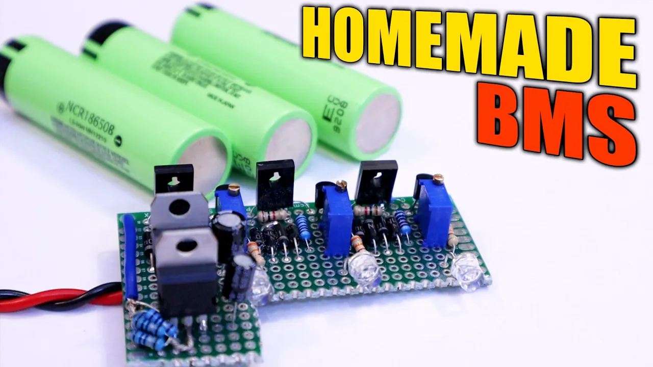
Homemade BMS - Balanced LiPo Charger Multiple Cells and Current Limit
286.3K
Adding current limit protection requires an LM317 regulator in current mode, where current limit equals Vref (1.25V) divided by the sense resistor value. Five 10Ω resistors in parallel create 2Ω total resistance for 600mA limit. A second LM317 at the input regulates output to 4.2V regardless of input voltage (5V-20V), enabling flexible power supply options. The complete BMS scales to multi-cell packs by connecting identical circuits in series—each monitors one cell. For a 3S pack, input voltage is set to 16-20V while output regulates to 12.6V (3×4.2V). LEDs indicate when each cell reaches full charge. Potentiometers allow threshold adjustment. This modular approach enables building BMS systems for any number of cells using standardized circuit blocks.
Click to watch →
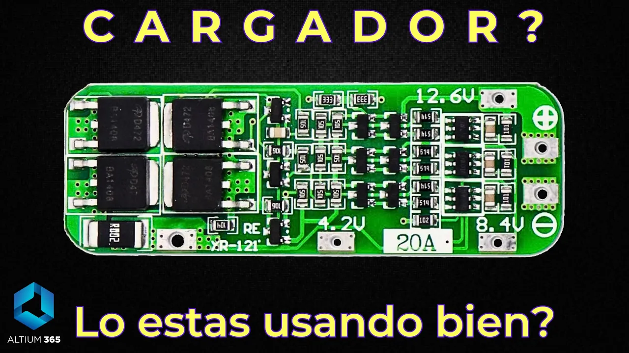
Es cargador o es protector/balanceador? | Cargador baterías de Litio BMS | Sponsor Altium365
68.1K
This section covers Battery Management System (BMS) architecture for multi-cell battery packs. BMS circuits use integrated circuits like the DW01A to monitor each cell's voltage and activate bypass transistors when cells reach full charge (4.2V). This prevents overcharge while other cells continue charging. For charging multi-cell packs from USB (5V input), boost chargers like the CN3303 are required, available in 2S, 3S, and 4S configurations. The 3S configuration is most common because it provides 12.6V output, which can replace many 12V applications.
Click to watch →

cargar 2 o mas BATERIAS DE LITIO con un modulo BMS
127.3K
A Battery Management System (BMS) module enables safe charging and monitoring of multiple lithium battery cells connected in series, with each 3.7V cell requiring independent protection; for a 2S configuration (two batteries in series totaling 7.4V nominal), the BMS provides overcharge protection at 4.28V per cell and over-discharge protection at 2.9V per cell, while the same connection points serve as both charging input and power output for the device.
Click to watch →

VDI Vortrag: Design und Aufbau eines DIY Batteriespeichers - Inklusive Weltpremiere unserer KI: LiLi
99.3K
A Battery Management System (BMS) monitors individual cell voltages in series-connected batteries and disconnects the entire pack if any cell reaches its maximum voltage (typically 4.2V). This prevents overcharging of weaker cells and protects against thermal runaway. The BMS is essential for safe operation of multi-cell battery packs.
Click to watch →
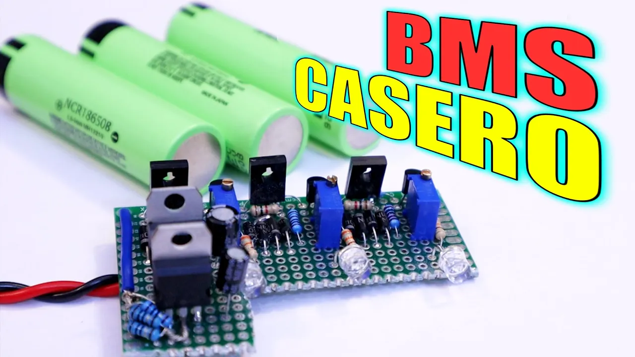
BMS Casero | Carga Balanceada Múltiples Barterías | Límite Corriente
171.4K
Advanced BMS functionality extends beyond basic overvoltage protection to include current limiting and multi-cell balancing. Current limiting is implemented using LM317 regulators in current mode, where the limit follows I = VR/R with VR = 1.25V. Multi-cell balancing scales single-cell circuits to monitor and disconnect each cell individually when reaching 4.2V, preventing overvoltage in multi-cell packs (2S, 3S, etc.). Combined voltage regulation fixes output at 4.2V per cell regardless of input variations. These features enable safe charging of complex battery configurations while maintaining individual cell health through precise control and isolation mechanisms.
Click to watch →
Motor Test
Blade Boost
Motor Test
0:20- 1
Salvaged DC motor from printer tested for voltage output.
- 2
Aerodynamic blade shaping increased voltage from 1.5V to 1.73V.
- 3
Potential use for charging AA batteries in parallel.
Limitations of Brushed DC Motors and the Necessity of Electronic Power Conditioning
While using a micro brushed DC motor and relying on blade design to boost voltage is a popular educational project, it is highly inefficient for practical wind power generation. Brushed DC motors suffer from high internal resistance, friction, and brush wear, making them poor generators compared to brushless alternators. Furthermore, relying purely on aerodynamic blade design to match battery charging voltage (e.g., boosting from 2V to 4V) is unreliable due to fluctuating wind speeds. A standard engineering approach utilizes electronic power conditioning, such as step-up (boost) DC-to-DC converters or Maximum Power Point Tracking (MPPT) controllers. These electronics dynamically adjust the voltage and current to match the battery's charging profile, ensuring safe, efficient, and consistent power transfer regardless of wind variability, while preventing the battery from discharging back through the motor during low-wind conditions.
Basic principles of electromagnetism, specifically how a DC motor can function in reverse as an electrical generator.
Fundamental electrical concepts such as voltage, current, resistance, and how to safely use a multimeter to measure them.
The basics of battery chemistry and charging requirements, including nominal voltage thresholds for rechargeable cells like AA batteries.
Elementary aerodynamics, particularly how wind flow exerts force on a turbine blade to produce rotational torque.
Designing and implementing voltage regulation circuits, such as DC-to-DC boost converters, to stabilize fluctuating generator outputs.
Understanding charge controller circuit design, including the use of blocking diodes to prevent battery discharge back into the motor.
Exploring power optimization techniques like Maximum Power Point Tracking (MPPT) for micro-scale wind generation.
Scaling up renewable energy storage systems, including battery management systems (BMS) for multi-cell packs.
90.7K views208likes3:49@wtam69Original Release: 2013-04-24
what I have here is another small motor that I took out from my Epson printer this one is a DC motor and I'm trying to see what kind of voltage I can get out of this apparently it's a very high RPM Motor so it needs to be turning very fast but I was thinking just using this motor to charge a small maybe a set of double a batteries in parallel so I would need no more than 1.6 volts or so I would have to get a small dial and I just happened to have a sh key dial that I can use also taken out from the Epson printer actually I tested it before and I was getting about 1.5 volt and you see the shape of these blades that I just made for testing purpose when I flatten the the blades it goes a little bit faster so that's what I'm going to do I'm going to flatten it some more than before okay let's try it of course I can gear it up but that complicates the process you would have to engineer quite a bit more right now it's going up to 1.73 volts so I modify the plates a little bit making it a bit more aerodynamic and the volage has gone up [Music] three [Music] volts 8.7.9 4 volts making the blades more aerodynamic more air foil shape does help voltage went up from 2 Vols to 4 volts so this is how it looks maybe if I make the blades thinner it would help maybe I cut off this part here that would help too I'm sure [Music]
Up Next

5:36
Fluid Shear Stress & Viscosity Explained | Fluid Mechanics
@TadhgODonovan1
68.7K views•2013-08-07

30:32
Ultrasonic Transducers: Resonant Frequency Measurement and Horn Design
@imajeenyus42
229.9K views•2017-02-22

54:16
Polymer Environmental Degradation: Mechanisms & Stabilization
@iit
1.8K views•2012-07-10

33:39
How a Student's Question Saved a NYC Skyscraper from Collapse
@veritasium
22.8M views•2025-04-26
Related Study Plans & Knowledge Roadmaps
Structured learning paths in Engineering
engineering
Building Acoustic Levitators: Physics & Arduino
01The Physics of Sound and Standing Waves
02Piezoelectric Transducers and H-Bridge Drivers
03Arduino Programming: Generating 40 kHz Signals
+ 2 more learning modules
14h5 modules
Explore Roadmap
engineering
Building Peltier Cloud Chambers: Particle Tracks
01Cosmic Rays & Cloud Chamber Physics
02Thermoelectric Cooling (TEC) Fundamentals
03Custom Liquid-Cooling Loop Design
+ 2 more learning modules
18h5 modules
Explore Roadmap
engineering
Yagi-Uda Antennas: Modeling, Build & VNA Test
01Introduction to RF and Antenna Fundamentals
02Yagi-Uda Antenna Design Principles
03Antenna Modeling and Simulation in 4NEC2
+ 2 more learning modules
18h5 modules
Explore Roadmap
engineering
ECG Monitor Design: Op-Amps, Filters & Noise
01Electronics & Breadboard Basics
02Op-Amps and Instrumentation Amplifiers
03Bioelectricity and ECG Fundamentals
+ 2 more learning modules
18h5 modules
Explore Roadmap