








![#72 | ARMATURES ET ANIMATION - Débuter sur Blender [TUTO FR]](https://i.ytimg.com/vi_webp/4IvNtSlQL_k/maxresdefault.webp)


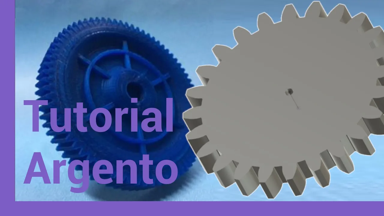
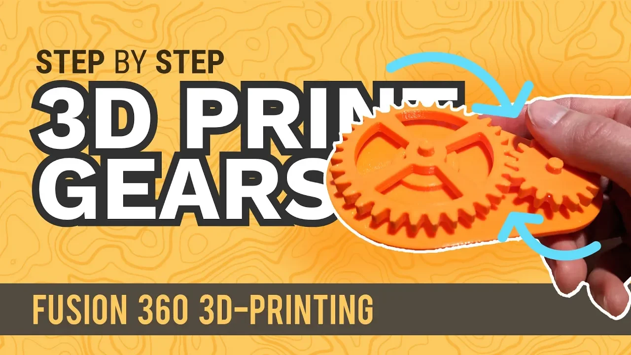







This tutorial demonstrates how to design and test rack-and-pinion mechanisms in Blender using five key parameters: number of teeth, module (which determines gear size and tooth spacing), pressure angle (typically 20°), profile shift (required for pinions with 18 or fewer teeth to prevent tooth overlap), and helix angle/width for helical gears; the process involves creating gear profiles using mathematical equations from an online calculator, constructing the pinion and rack geometry through extrusion, rotation, and duplication techniques, and finally testing compatibility using Blender's rigid body physics engine with hinge and slider constraints.
Modeling a Rack and Pinion Mechanism in Blender
Added:Basic Blender navigation and hard-surface modeling techniques, including mesh editing and modifiers (such as Boolean and Array).
Fundamental concepts of Blender's rigid body physics engine, specifically active vs. passive rigid bodies and collision shapes.
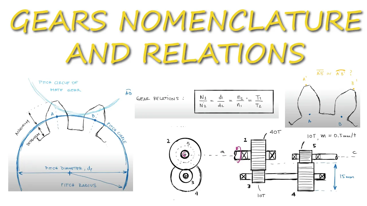
Basic mechanical principles of gears, including the concept of gear teeth pitch, spur gears, and helical gear geometry.
Precision alignment techniques in Blender, such as utilizing the 3D cursor, snapping options, and setting origin points.
Rigging mechanical assemblies using Blender's Armatures, Bones, and Drivers for deterministic, non-physics-based animations.
Designing gear systems with realistic mechanical tolerances (backlash and clearance) for 3D printing and rapid prototyping.
Simulating complex mechanical transmission systems, such as planetary gear sets, worm drives, or differential gearboxes.
Exporting Blender mechanical models to CAD software for engineering validation, motion study, and Finite Element Analysis (FEA).
59.2K views455likes13:02Original Release: 2017-03-22
In this tutorial, you will learn how to model a rack and pinion in Blender and test them for compatibility using Blender's rigid body physics engine. The rack and pinion profiles can be fully defined by these five parameters. Number one, the number of teeth on the pinion. This parameter is self-explanatory.
Number two, module. This parameter measured in length units defines how big or small the gear is. The physical diameter of the gear equals the module multiplied by the number of teeth. The module also determines the linear distance between the teeth of the rack. Number three, pressure angle. This parameter is normally 20°.
Number four, profile shift. When the number of teeth on the pinion is 18 or less, the standard semic-ircular gaps between the teeth are not deep enough to accommodate the teeth of the mating rack. A positive profile shift sharpens the tooth profile, increases the mounting distance between the pinion and rack, and eliminates the overlap. Number five, helix angle and width. These parameters are only applicable if the pinion has helical teeth. We have developed an online calculator which generates the profiles and dimensions of the rack and pinion based on these parameters. This calculator can be found at www.vinted.com/rack.html. Let's start modeling. Delete the default cube.
Press seven on the numeric keypad to switch to the top view and five to switch to the orthographic mode. Select 3D cursor as the pivot point. In user preferences, open the add-ons tab and make sure add mesh extra objects is checked. Press shift A. Select mesh math function XYZmath surface. Go to the online calculator at www.vint.com/ra.
vinted.com/rack.html. Enter 12 for the number of teeth. Press calculate.
Increase the profile shift value by small increments until the warning goes away. Keep the width and helix angle boxes blank for now. Copy the X and Y equations to Blender.
Enter zero for Z equation, zero for U min, one for U max, and 10 for U step.
Uncheck the U wrap box. Press tab to enter the edit mode and press the remove doubles button.
Duplicate and create a mirror reflection relative to the X-axis by pressing shift D, then S, then Y, then minus one, then enter. In the calculator, copy the tooth thickness at base value to the clipboard. Back in Blender, rotate around the Z-axis by this value by pressing R, then Z, then Ctrl +V, then enter. Select the two rightmost vertices and press F to create the tip of the tooth. Select everything, duplicate, and rotate around the Z-axis by 30°, which is 360 divided by the number of teeth.
Select these two vertices. Press shift S and select cursor to select it. Unselect the top vertex. Press the spin button.
Enter 16 for steps and 180 for angle.
Select everything and press remove doubles. Press shift C to return the 3D cursor to the origin. Press the spin button. Enter the number of teeth or 12.
For steps, check the duply box and enter 360 for angle. Select everything and press remove doubles. Note the number of vertices in the geometry. Add a circle with the same number of vertices. Scale it up. Select everything. Press W and select bridge edge loops. The basic outline for our pinion is ready. Press tab to exit the edit mode. Call it pinion.
Press shift A. Select mesh single vert.
Add single vert. In the calculator, copy the slanted addendum and add dendum value to the clipboard. Back in Blender, extrude upwards along the Yaxis by this value by pressing E, then Y, then Ctrl +V, then enter.
Select the bottom vertex and move it downwards by pressing G, then Y, then the minus sign, then Ctrl +V, then enter. Select everything. Rotate by the pressure angle or 20° clockwise by pressing R, then Z, then -20, then enter. Select the top vertex. In the calculator, copy tooth tip length to the clipboard. Back in Blender, extrude to the right by pressing E, then X, then Ctrl +V, then enter. Select both top vertices. Press shift S and select cursor to selected. Select everything. Duplicate and create a mirror reflection by pressing shift D, then S, then X, then minus one, then enter. Select everything and press remove doubles. In the calculator, copy the pitch value to the clipboard. Back in Blender, duplicate and move to the right by that amount by pressing shift D, then X, then Ctrl +V, then enter. Select these two vertices.
Press shift S and select cursor to selected. In the calculator, copy the fillet center shift value to the clipboard.
Move the 3D cursor upwards by that amount by pressing N to show the properties panel and increasing the Y-coordinate by the value from the clipboard. In the calculator, copy the fillet angle to the clipboard. Deselect the left vertex.
Press the spin button. Enter 10 for steps. Uncheck the duply box and paste the angle value from the clipboard.
Select everything and press remove doubles. In the calculator, copy the pitch value to the clipboard again. Back in Blender, duplicate and shift to the right by that amount by pressing shift D, then X, then Ctrl +V, then enter. Press Shift R to repeat the previous operation several times to create more teeth for the rack.
Select everything and press remove doubles. In the calculator, copy the mounting distance to the clipboard. Back in Blender, move the geometry down by that amount by pressing G, then Y, then negative sign, then Ctrl +V, then enter. Move the geometry to the left as far as necessary, and make sure the teeth of the pinion and rack mesh nicely.
Extrude downwards along the Y-axis by a reasonable amount such as five by pressing E then Y then -5 then enter.
Press shift S and select cursor to selected. Align the selected vertices by pressing S, then Y, then zero, then enter. The basic outline for the rack is complete. Call it rack. Extrude along the Z-axis by five, which is going to be the width of both rack and pinion. Press C, then double Z, then five, then enter. Select everything and press CtrlN to fix the normals.
Select the pinion. Press tab to enter the edit mode and extrude along the Z-axis by five.
Also, select everything and press CtrlN to fix the normals. Our rack and pinion are ready to be tested for compatibility using Blender's rigid body physics engine.
Press shift C to return the cursor to the origin. Add a cylinder, call it axis. Add an empty and move it up. Call it hinge.
Add an empty. Rotate it around the Y-axis by 90°. Move it up. Call it motor. Add an empty. Move it toward the pinion. Call it slider. Select pinion. Go to the physics tab. Click rigid body.
Select mesh for shape and zero for margin. Select track. Click rigid body.
Select mesh for shape and zero for margin. Select axis. Press rigid body.
Select passive for type. Select hinge.
Click rigid body constraint. Select hinge for type. Pinion for object one and axis for object two. Select motor.
Click rigid body constraint. Select motor for type pinion for object one and axis for object two. Click enable under angular motor. Select slider. Click rigid body constraint. Select slider for type rack for object one and axis for object two. Our setup is ready. Press play to start the simulation.
Now let's make the rack and pinion helical. In the calculator, enter five for width and 30 for helix angle. Press calculate. In the bottom part of the calculator, two new values appear. Pinion spiral angle per division and rack's shift per division. The default number of divisions for the pinion is eight and for the rack four.
These can be increased or decreased if necessary. Eight divisions correspond to seven loop cuts and four divisions to three loop cuts. Back in Blender, give the pinion seven loop cuts and the rack three loop cuts. In the calculator, copy the pinion spiral angle per division value to the clipboard. Back in Blender, select the pinion, put the 3D cursor on it, enter the edit mode, and select everything. Then deselect the entire bottom layer of vertices. Rotate around the Z-axis by the angle stored in the clipboard by pressing R, then Z, then Ctrl +V, then enter. Unselect the next layer and repeat the rotation operation for all remaining layers.
exit the edit mode. In the calculator, copy the rack's shift per division value to the clipboard. Back in Blender, select the rack. Enter the edit mode. Select everything. Deselect the entire bottom layer of vertices. Move by the distance stored in the clipboard along the X-axis by pressing G, then X, then Ctrl +V, then enter. Unselect the next layer and repeat the moving operation for all remaining layers. Exit the edit mode. If everything was done correctly, the top and bottom layers of the rack and pinion should still mesh nicely. Press the play button. And that concludes our tutorial.
Up Next

13:18
How to 3D Print Functional Planetary Gears: DIY Guide & Test
@Barnacules
1.2M views•2013-05-22

12:54
Triumph of Orthodoxy Icon: Byzantine Art & History Explained
@BenCallan
2.1K views•2024-08-06

9:49
FastAPI vs Flask vs Django: Choosing the Right Python Web Framework
@TechWithTim
302.5K views•2024-05-26

1:42
Game of Thrones Opening Credits: A Cinematic Analysis
@gameofthrones
46.3M views•2011-04-18
Related Study Plans & Knowledge Roadmaps
Structured learning paths in General & Interdisciplinary Studies
general-studies
Elevator Engineering: History, Physics & Cities
01From Hoists to Safety Brakes: The Dawn of Vertical Lift
02Hydraulic vs. Traction: The Engineering Physics of Elevators
03Modern Speed, Safety, and Algorithms
+ 2 more learning modules
12h5 modules
Explore Roadmap
general-studies
Rubber: Material Science, History & Geopolitics
01Origins of Natural Rubber & Mesoamerican History
02The Chemistry of Natural Rubber & Vulcanization
03The Geopolitics of the Rubber Boom & Colonization
+ 2 more learning modules
12h5 modules
Explore Roadmap
general-studies
Containerization: Evolution, Logistics & Trade
01Ancient Trade & Bulk Cargo: Amphorae to Barrels
02The Industrial Revolution & Cardboard Packaging
03The Containerization Revolution: Malcom McLean
+ 2 more learning modules
12h5 modules
Explore Roadmap
general-studies
Textile Tech: Evolution, Labor & Global Impact
01Pre-Industrial Textiles: Handloom & Cottage Industry
02Mechanization: The Spinning Jenny to the Power Loom
03The Factory System & Global Labor Transformation
+ 2 more learning modules
10h5 modules
Explore Roadmap