

![AP Psychology Unit 1 Review [Everything You NEED to Know]](https://i.ytimg.com/vi_webp/4yvfd8aoUBc/maxresdefault.webp)




















Ultrasound is a mechanical pressure wave measured in Hertz, with diagnostic ultrasound operating above 20,000 Hz; key principles include the inverse relationship between wavelength and frequency, the reverse piezoelectric effect for sound generation, and the pulse-echo principle for imaging. The speed of sound varies through tissues (1,040 m/s in soft tissue, 330 m/s in air, 4,030 m/s in bone), affecting penetration and resolution. Higher frequencies provide better resolution but less penetration, while lower frequencies offer deeper penetration but reduced detail. Common imaging modes include B-mode (grayscale), M-mode (motion), and Doppler (color and spectral) for detecting blood flow. Transducers use piezoelectric crystals with matching layers to optimize sound transmission. Key artifacts include shadowing (high acoustic impedance interfaces), posterior acoustic enhancement (fluid-filled structures), lateral cystic shadowing (refraction at fluid interfaces), mirror images (strong reflectors), and reverberations (multiple internal reflections). Proper probe orientation follows conventions where the indicator points toward the patient's right or head, with sagittal, coronal, and transverse planes defined accordingly. Echogenicity describes tissue brightness relative to surroundings, classified as hypoechoic, isoechoic, hyperechoic, or anechoic.
Ultrasound Physics for Emergency Medicine: Modes, Probes, Artifacts, Orientation
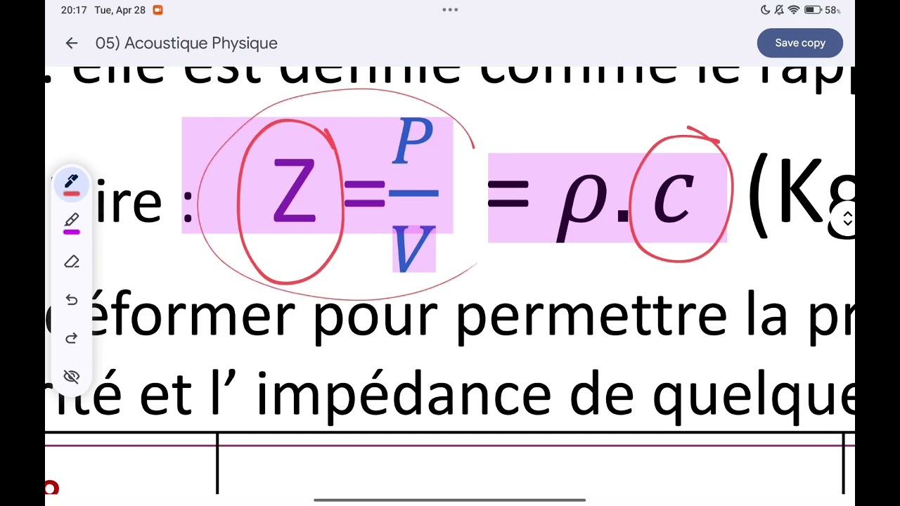
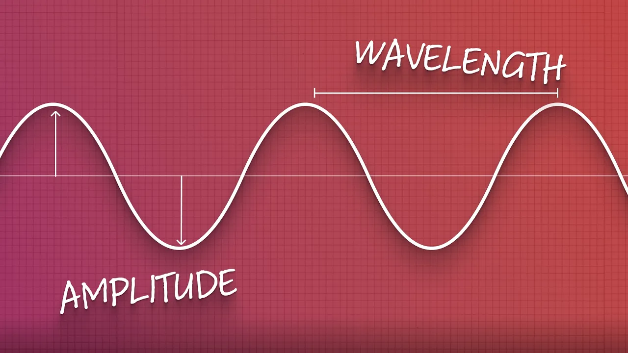
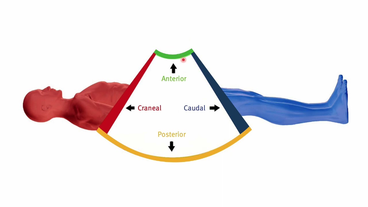
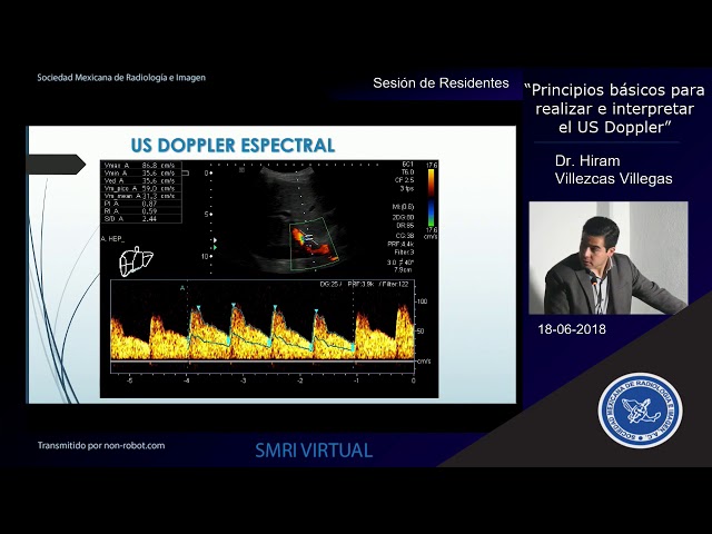
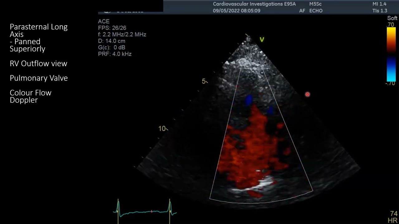
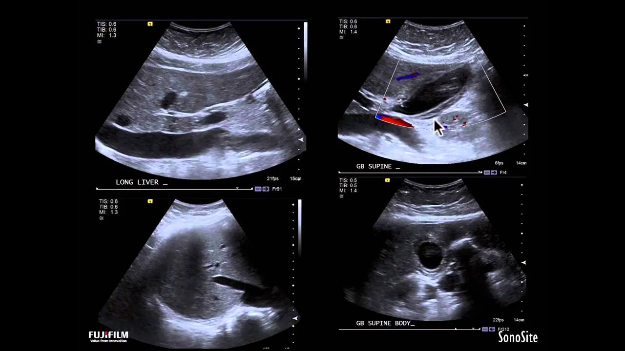
Added:we're going to discuss ultrasound physics and some basic principles we'll be reviewing the definition of ultrasound a little bit about physics transducers artifacts and some basic terminology you need to be aware of ultrasound is a mechanical pressure wave as all sound is and it's measured in cycles per second denoted by the unit hurt now audible sound at which we can hear is 20 to 20,000 Hertz ultrasound is anything above the 20,000 Hertz range but medically diagnostic ultrasound is roughly in the 2 megahertz range or higher or 200,000 Hertz and higher sound is described by its wavelength and frequency and you can see here the wavelength is the distance from a point to another point on the wave and frequency is the number of cycles per second or the number of occurrences over time so if we look at the red marker the number of waves that pass over that area per unit of time is the frequency and frequency and wavelength are inversely related so you can see here we have one wavelength with a set frequency as we have a shorter wavelength we have an increased frequency because there'll be more waves passing over certain area per second and if we have a longer wave there is a lower frequency now ultrasound is a pressure wave and what happens is it causes tissue to vibrate and that tissue vibrates and causes areas of compression where the molecules and the elements of that tissue are closer together and air is a rarefaction where they are more spread out and this is how that pressure wave propagates through tissue let's discuss some basic echo principles and topics related to ultrasound the first is the reverse piezoelectric effect what happens is when charge is applied to a piezoelectric substance it vibrates and creates a pressure mechanical wave the reverse or the piezoelectric effect is when that pressure wave stimulates the crystal and the crystal produces electronic effect and this is how ultrasound is produced from your transducers and what happens is the pulse echo principle is that sound is transmitted from the transducer to a tissue and that tissue then reflects the sound back to the crystals and the transducer and allows you to make an image the echo range principle means that it takes longer for sound to reach certain things and by calculating the speed of sound through that tissue we can determine how far away that substance is and that's how you can have distance displayed on your screen because the distance is correlated to the speed of sound and the time it takes for that sound to be reflected back to the transducer all of this is based on the speed of sound and the speed of sound is related to the density of the tissue the propagation of sound through that tissue in the speed of sounded cell you can see that in air sound travels at roughly 330 meters per second whereas in bone it travels at four thousand thirty meters per second and the all-important tissue is 1040 meters per second and this is the default that ultrasound machine assumes sound is traveling too it assumes we are all made of homogeneous tissue and sounds propagated and travels at 1040 meters per second acoustic impedance is the resistance to propagation of sound this is dependent on the density and the velocity of sound measured in mega rails it has a very low acoustic impedance at very low levels bone has a very high acoustic impedance at oppose you can see as a mid-range at one point three four mega rails however liver I have one point six five mega rails is just slightly different but that a little bit of difference does make a difference in sound reflection you can see here with two different acoustic impedances sound will transmit and with the greater difference between the tissues and the greater difference in acoustic impedance more sound is reflected back to the transducer making a brighter echo attenuation is the weakening of sound as it is transmitted and returned now attenuation occurs that sound is propagated through tissues and weakens as it travels through the tissue reflection also weakens the sound because as sound is returned to the transducer less sound is transmitted through the tissue meaning less sound will be reflected from deeper structure another way that sound being is weakened is by reflection some sound is returned to the transducer meaning less sound is propagated through the tissues but some sound may also be reflected in the direction that does not return to the transducer or propagate further into the tissue and that sound energy is lost scattering is when sound is reflected in a manner that it does not return to the transducer and that information is lost there's also absorption or sound is transformed to heat and absorbed by the tissues heating the tissues but also weakening the sound there are multiple modes of ultrasound that will cover a mode or amplitude mode will have the reflection and you'll see the sine wave where you see different amplitudes as sound as reflected back this is not very commonly used in diagnostic ultrasound anymore and instead we use B mode or grayscale imaging the most common eltra sound mode you'll run into is B mode or brightness mode or all commonly known as grayscale image you see here each of the pixels has a brightness and is displayed somewhere from black to white on a grayscale hence the two names B mode or brightness mode or grayscale M mode is motion mode and what will happen is there'll be a mode spike or that green that you see and what happens every motion over that line over time will be plotted on a graph tracing you can see this is commonly used in echocardiograms we're looking at valve motion the Doppler effect means that a moving object will change the frequency of sound so as objects are moving the frequency of reflected sound is altered and by interpretation of that change in frequency the ultrasound machine can denote motion the most common when you may see is color Doppler and the acronym to remember is Bart or blue away red towards meaning blue is coded for motion away from the probe and red is motion towards the probe you can see here in this office an image of a ear order with bi-directional flow you can see that there is red and blue flow as the blood is swirling around in different directions in motion towards the probe and away from the probe remember the color does not denote arteriovenous flow but rather Direction related to the probe by convention we try to make our turfs appear red and veins blue however this is merely by a physician power Doppler looks at the intensity of the deflectors rather than the actual frequency shift and this is useful for low flow states such as small vessels or ureters with urinal Jets within the bladder spectral Doppler looks at the velocity of the reflectors going through the gate and the Doppler shift of those deflectors and then maps it on a wave format and there's an audio component because the frequency shift is within the audible range you can see here a grayscale image and we'll place the Doppler gate within the vessel now looking at any of the deflectors traveling through that gate between the two green bars it will map out those deflectors on a graphical scale like this now let's discuss the different types of transducer the transducer function based on the piezoelectric principle and there are a key element of the system they're also the most expensive and the most fragile component of the system most modern transducers use synthetic crystals such as LEDs are connected tuning these are heat sensitive and the probe should never be autoclaved for sterilization the reason being that the heat can miss align the crystals and render your probe useless the crystals are generally housed within the transducer a backing layers behind the crystal and a matching layer front the backing layer prevents any pressure waves from exiting the crystals in a reverse fashion and tries to direct all the sound energy forward it travels through the matching layer to try and reduce the acoustic impedance between the crystals themselves and the skin that's that soft spongy layer you see on the surface of the probe electricity is introduced in this system stem you in the crystals to produce the pressure wave the backing layer prevents sound from transmitting and reflecting from the back of the crystals and they exit the matching layer through the skin into the subject broadband transducers are transducers that can produce multiple different frequencies rather than a single frequency like in older systems and you can select a different frequency and because of this you need to understand that higher frequencies will give you greater resolution but less penetration lower frequencies will give you greater tissue penetration but sacrifice resolution you can see an example here we have a sound wave as it travels through the tissue it interacts with the tissue at several point you can see that each time it interacts it with it that sound beam will be attenuated and weakened and be able to travel less if that sound beam interacts with the tissue very frequently we'll have a lot of attenuation a lot of weakening of that sound beam and I won't get very far however it will have interacted with that tissue in multiple areas and give you a better resolution however with the lower frequency will have less resolution because there's less interaction with the tissue but with that less interaction there will also be less attenuation and sound beam or penetrate deeper now there's multiple types of probes and depending on your type of ultrasound system they may look slightly different based on the casein and the model while ultrasound probes are designed differently by different manufacturers the basic type of probes are similar throughout you can see the linear array which is a rectangular phase own this sends our beams in a very parallel fashion giving you a rectangular display on the ultrasound screen a curved array is a linear rate that is Miss lightly curved you can see that the beams plays out giving you a wider field in the deeper portion of the image but the sound beams are located closer together in year-2 the probe and the cavity probe or intra cavatelli probe is merely a curved array with a very tight curve on a longer hand the phased array which is commonly used in cardiac imaging but can also be used for abdominal imaging as a very narrow window but has a very great display so this is very useful for cardiac imaging because the point of contact can be very small to fit in between ribs and round lung artifact but has a very wide field of view the resolution of your ultrasound images based on several things one is based on frequency and one is based on the type of probe you use lateral resolution or the ability to tell that two objects side by side R and D two objects and not blur into one object is based on your beam width if you look at the linear array here on the right side you see those lines or lines of sight in the ultrasound beam are equally spaced near the probe and far probe giving you that rectangular image so the distance between lines of sight are fairly uniform near and far from the probe this produces a greater lateral resolution where as you see in the phase array the lines of sight are very close together near the probe but very far apart as explained outwards deeper into the image reducing your lateral resolution deeper into the view extra resolution or the ability to tell that two objects one in the near field and when the far field are actually two objects are not blurred into one object is based on your frequency higher frequencies allow the sound beam to interact with the tissue more frequently allowing you to differentiate X or resolution much clearer than with the lower frequency is displayed on the left of the screen axial resolution will always be greater than lateral resolution let's discuss some artifacts that you may run into as part of using ultrasound artifacts are based on several presumptions that the ultrasound machine makes one of which is that sound travels only in a straight line sound speed is uniform throughout tissues a single pulse from the probe is emitted and returned attenuation is uniform as signals only occur from the main beam of the ultrasound shattering artifact is produced when there is a high difference in acoustic impedance what happens is there is a high attenuation of the sound beam and that sound because of the high acoustic impedance is reflected back to the transducer making a very bright image but no sound is transmitted past that interface you can see here in the gallstone we can see the brain interface where the sound beam is reflected from the gallstone now the gall stones not calcified but it can have very high acoustic impedance compared to the tissue around it and therefore sound does not penetrate further and this area highlighted in black would be the area of of acoustic shadow meaning that sound does not transmit it past that surface you can see here as we scan through a gallbladder with multiple stones you can see the area where the stones are and the sound beam is reflected back to the probe with shadowing behind posterior acoustic enhancement occurs when there's a very low attenuating circle and this occurs when there is a fluid interface now the fluid does not interact with sound beam as it does with solid tissue and therefore the sound beam is not weakened so the sound being remains very strong so when that echo returns from behind the fluid structure it has not been attenuated as greatly as that they travel through tissue the ultrasound machine interprets this as a greater signal and makes those images brighter you can see here behind the fluid fill bladder the soft tissue is very echo Jenica very bright much more than the surrounding struck first and this is because the sound that has traveled through the bladder has not been weakened as it is only traveled through fluid rather than tissue compare the lateral aspect and the sound that is reflected is much stronger meaning much brighter d focus a artifact occurs when there is a fluid interface and what happens is the fluid bends the sound beam and it causes a deep focusing artifact most commonly you'll see this as called lateral Cystic shadowing meaning that as the sound being travels to that fluid interface it is slightly bent there's a slight refraction of the sound beam causing some echo drop out towards the edges because the sound that would have traveled through that tissue behind it has been bent inward you can see here on the internal jugular vein there's evidence of lateral Cystic shadowing here because the sound beam that would have traveled into that tissue has been bent slightly inward marryin artifact is because when sound travels it hits a very strong reflector it bounces off that reflector to interact with tissue returns through that deflector and returns to the probe however the probe and the Machine assumes that sound is only traveled in a straight line it therefore takes that reflected sound and mapped it in a straight path you will most commonly see this in your fast exam when you're looking about the liver a sound beam interacts with the diaphragm reflects off the diaphragm into the liver bounces off that tissue back off the diaphragm went back to the probe the effect of that is that it appears that there is liver on both sides of the diaphragm this is called the Marian artifact and it's a normal occurrence with aerated lung above the diaphragm you can see as we're scanning through you can see that the liver appears to be mirrored on both sides of the diaphragm reverberation artifacts occur when sound travels into tissue because of high reflection the sound bounces within that tissue and returns multiple signals to the probe because the probe assumes that ultrasound has traveled only in a single line those reflections and reverberations are then mapped in increasing depth throughout the image you can see here the reverberation line passing in through the bladder and you can see that it does cross anatomic boundaries leading you to the assumption that it is an artifact it is a reflection of the probe bouncing off the peritoneum on the anterior surface of the bladder you can see here that the ultrasound beam reverberates between the pleura and pneumothorax you can see those reverberation artifacts passing throughout the field of view here this is also what produces your B lines of pulmonary edema in pulmonary edema the space between the aerated lung and the demo tissue of the lung it's very small so there's reverberation lines are very narrow and very close together looking almost like a vertical line so let's discuss orientation and planes there's an indicator on the probe which aligns with indicator on the screen unfortunately indicators may vary by probe and by manufacturer orientation is based on the indicators and body orientation or abdominal preset orientation is based that the indicator will be pointed towards the patient's right the patient's head or somewhere within that 90 degree range and this is so that you can look at the ultrasound image and be able to orient yourself as the direction of the image so by convention the indicator probe should be pointed towards the patient's right their head or somewhere within that 90 degree plane so if you look at this ultrasound image both of a transverse and Satchel image because of the indicator and orientation Convention I can tell that on the transverse image we can tell which is right and which is left and on the cetera image we can tell which is cranial and caudal you can see here in a sad row image because my indicators oriented towards the patient's head I know that the indicator side of the image is towards the patient's head or cranial and the bottom of the image is towards his feet or caudal in a transverse image because the indicator is oriented to the patient's right I know that the right side of the image has indicator dot on it and the non indicator side is the patient's left making them structure measured is abdominal aorta and not as IVC let's discuss imaging plane sagittal images are cutting from anterior to posterior plane and the indicator would be oriented to which the patient's head a coronal view is cutting from lateral to medial and the indicator would also be pointed towards the patient's head a transverse view will be going from anterior to posterior and the indicator would be oriented to the patient's right now an oblique view would be somewhere within that 90 degrees and the indicator would be pointed towards the patient's right side or towards their head somewhere in that 90 degree range cardiac orientation is slightly different cardiac orientation has the indicator pointing towards the patient's head or their left side now unfortunately when we talk about head we're actually talking about the superior portion of the heart so the indicator should be pointed towards the superior portion of the heart and because a heart is an oblique structure we are scheduled to the heart and not necessarily the external anatomy of the patient you can see here that the indicator is pointed towards the external anatomy of the right shoulder but on the image it is actually pointing towards the top of the hard giving you a sagittal view of the heart rather than a sagittal view through the patient's body and mostly when we discuss specific organs we were talking about satchel and transverse in relation to that organ and not necessary external anatomy so once again in a cardiac preset we are sagittal view of the heart indicators towards the top of the heart or the head portion of the heart and then on indicator towards the foot or the bottom portion of the heart in a transverse view that indicators oriented towards the patient's left side so then when I look at the image you can see a transverse cut through the left and right ventricle and I know which is the left and which is the right ventricle based on probe orientation let's discuss some ultrasound terminology used to describe images and this is echogenicity the amount of echoes or the amount of whiteness within an image determines its echogenicity and it can be hypoechoic hyper Koyuk isochoric or anechoic and it is a relative scale for instance we see more echoes within the circle meaning it is more white within the circle than the surrounding tissue so the circle is hyper a collec to the surrounding tissue the surrounding tissue is hypoechoic to the circle here we see that there is less echoes or less whiteness within the circle so the circle is hypoechoic to the surrounding tissue whereas the tissue is hyper collec to the circle here we can see that there's the same amount of Eckles within and without the circle so the tissues are I so a cork or of similar echogenicity the circle here is completely black and has no echoes within it so it is anechoic you can see here on this image of the lower thorax with a dalit attic lung spleen and a pleural effusion we can use those descriptors to describe the image the collapse lung and the spleen are I select to each other the spleen and the spine are different equitation City the spleen is hypoechoic to the spine the spine is hyper Koyuk to the spleen here at the pleural effusion which is fluid is a Nicole don't forget to follow on YouTube Twitter and subscribe to the channel
Up Next

Deriving the Radial Velocity Equation | Exoplanet Detection Series
@CoolWorldsClassroom
3.3K views•2020-07-08

21cm Hyperfine Transition in Neutral Hydrogen: Radio Astronomy Basics
@AaronRobertParsons
12.4K views•2011-10-13

NMR Spin Physics I: Zeeman Effect, Resonance Condition & Larmor Frequency
@nptel-indianinstituteofsci8064
2.3K views•2024-01-17

Entropy and the Second Law of Thermodynamics Explained
@veritasium
27.5M views•2023-07-01
Related Study Plans & Knowledge Roadmaps
Structured learning paths in Physics