
![Ардуино уроки программирование для начинающих с 9 лет [с нуля] #ДомаВместе](https://i.ytimg.com/vi/RwO_4nhRTUM/maxresdefault.jpg)




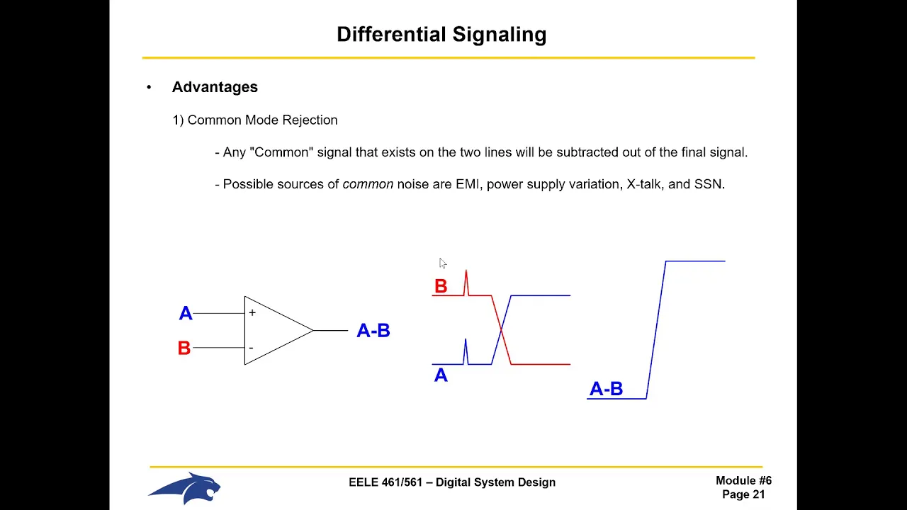





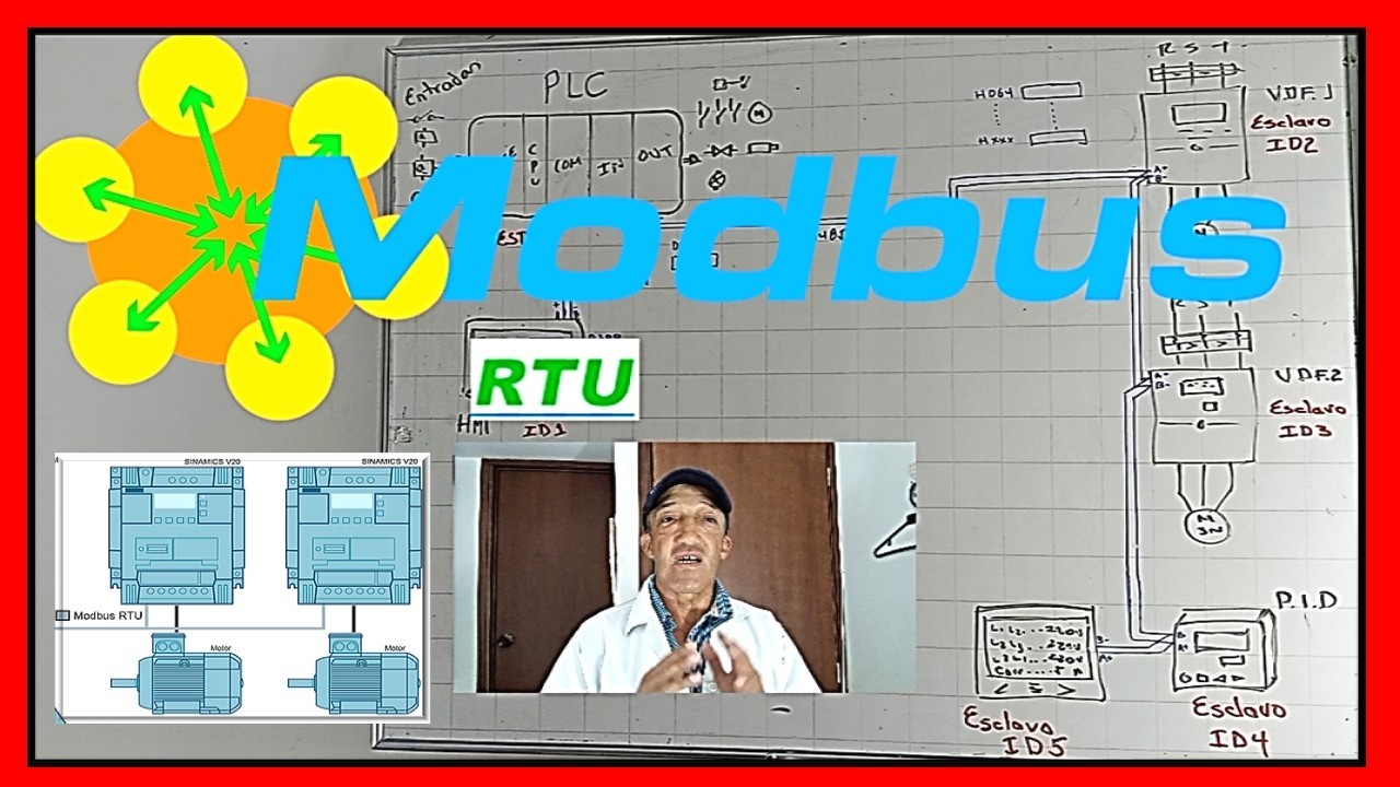


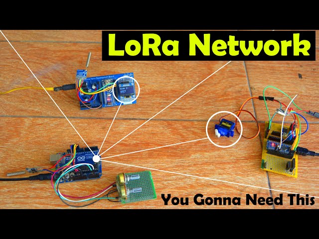





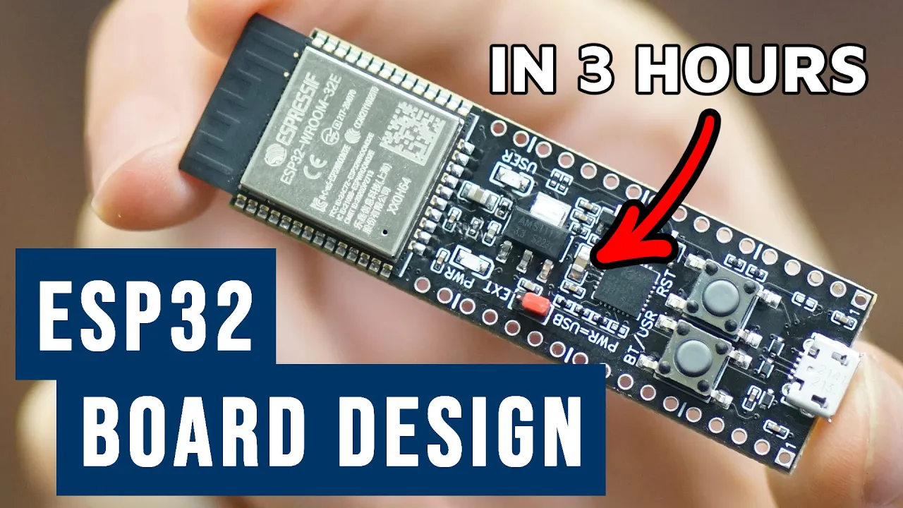




RS485 modules enable reliable serial communication between Arduino boards over long distances (up to 4000 feet) using differential signaling, where two wires carry complementary signals that eliminate common mode noise; the DE/RE pin controls signal direction, and a simple implementation involves connecting TX to DI and RX to DO with proper ground connections, allowing multiple devices (up to 128) to share a single bus.
Max485 RS-485 Module Tutorial: Arduino Differential Serial Communication
Added:Basic Arduino programming and familiarity with the Arduino IDE environment.
Fundamental concepts of UART/USART serial communication, including Tx, Rx, and Baud Rate.
The difference between single-ended signaling (like standard TTL serial) and differential signaling.
Basic breadboarding skills and understanding of common electrical concepts like VCC, GND, and signal degradation over distance.
Implementing the Modbus RTU protocol over RS-485 for standardized industrial device communication.
Designing multi-drop (multi-device) networks using a Master-Slave architecture with addressable nodes.
Signal integrity optimization techniques, including the use of 120-ohm termination resistors and fail-safe biasing networks.
Comparing RS-485 with other industrial communication buses like CAN bus, RS-422, and Ethernet.
16.3K views178likes5:34Original Release: 2020-01-24
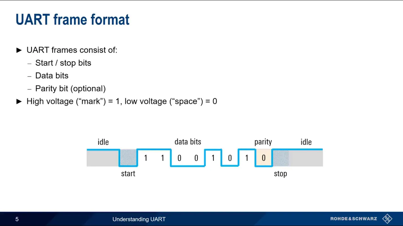
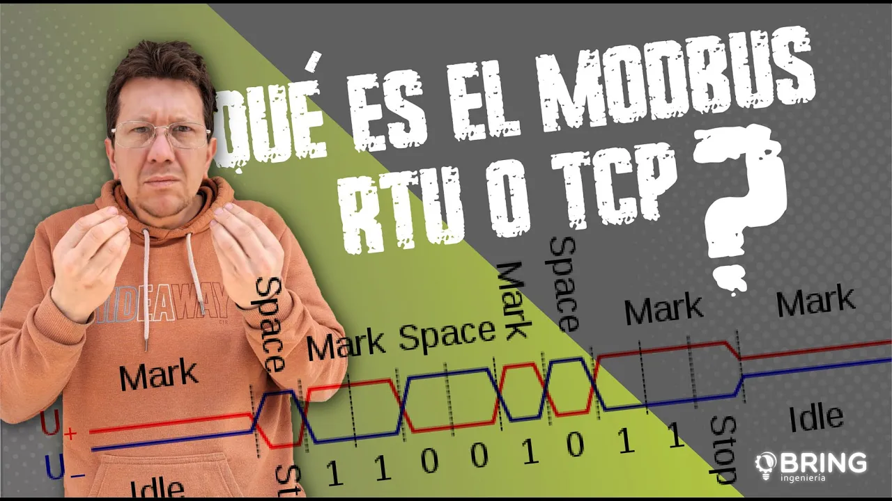
[Music] let's talk about hooking up a couple of these max 45 modules and we're going to run some Cyril data between two arduino z' and we're going to do this as simple as possible just see if the hardware works so on the sender here we're just gonna have this is the only code we're gonna use here and we're going to set the baud rate and then we're gonna sell print an H capital H and we're going to wait one second and then we're going to select print to capital L and we're gonna wait another second okay we're just going to go over keep doing that sending an H and an L and H and an L now over here on the receiver side in the arduino IE d under examples under communication under physical pixel they have a program and we're just going to use that program there and all that does is it it sets our pin output pin to 13 we set our baud rate if the serial is available we read the serial and we call that incoming byte and if that incoming byte happens to be an H then we're going to digitally write the pin 13 high and if that incoming bytes a capital L we're gonna digitally write that pin low so that's all we need to for our program and we're gonna connect up a couple of these modules to see if we can actually send the the code over there now these these work good because you get when you're putting in a so your we connect our TX to d1 here okay now when we send an H we're actually sending this just this binary code here you know zero one zero zero one zero zero zero so when we put in a zero on line and B here it's going to be a zero and the other line is going to invert it it's going to be a one so we're always sending an inverted signal or sending a 1 here and a zero here if we send a 1 here this is going to be a zero here it's called differential signaling and we're going to do it over a twisted pair and that eliminates a lot of the common mode noise okay and it allows us to send the sync for about 4000 feet are over a kilometer and we can we can have as many as 128 transceivers on one bus and so we're going to see if if we can actually get the hardware to work here so all right so I have two two separate power supplies I'll turn these on okay now what I'm going to do first is I'm not going to use the the max rs-485 s I'm going to connect directly from the trans TX of this Arduino to the rx over here this wire is not is is not in play here okay let's take that out so yeah I'm gonna just connect that right to the so we're running the the capital H and the capital L into this this guy here it's decoding it and it's blinking the light here and we don't have the these two modules hooked up at all all we have is one wire here that's from TX to rx over here and we're controlling it that way of course there is a ground between the two of them here so so you could run this with just two wires now we're not sending any information back we're only sending in one direction so we'll take that off and then we'll we'll put in the so there we go so now we're running the from the Tia TX were running into da di on this one and it's going through this twisted pair over to this side coming out of our o and running into the program we're sending the program down now on on these down here to hook up the here we just tie B to be a to a and we take to take a ground over there now down here when you're receiving you have to have de and re has to go low on the receiver okay now when we sending messages back and forth we'll have to switch from low to high on this but for now we're just going to receive so we can have de and re tied to ground and it's low and on this side here we have de and re and that's at +5 volts I just have that tight tied directly to to +5 volts over here so it just as simple as that it works you know you can go about 4,000 feet this way and we're sending some very simple code it's easy - I like to start off with a very simple code so that if there's any problems with the hardware or whatever it's easy to to find you don't have to worry about your code so yeah that's that's all you have to have for sending a signal to to another uh Arduino thank you
Up Next

3:00
DIY 5-Axis Analog Joystick Controller With Arduino
@amstudioprojects
164.8K views•2018-04-25

12:54
Triumph of Orthodoxy Icon: Byzantine Art & History Explained
@BenCallan
2.1K views•2024-08-06

9:49
FastAPI vs Flask vs Django: Choosing the Right Python Web Framework
@TechWithTim
302.5K views•2024-05-26

1:42
Game of Thrones Opening Credits: A Cinematic Analysis
@gameofthrones
46.3M views•2011-04-18
Related Study Plans & Knowledge Roadmaps
Structured learning paths in General & Interdisciplinary Studies
general-studies
Elevator Engineering: History, Physics & Cities
01From Hoists to Safety Brakes: The Dawn of Vertical Lift
02Hydraulic vs. Traction: The Engineering Physics of Elevators
03Modern Speed, Safety, and Algorithms
+ 2 more learning modules
12h5 modules
Explore Roadmap
general-studies
Rubber: Material Science, History & Geopolitics
01Origins of Natural Rubber & Mesoamerican History
02The Chemistry of Natural Rubber & Vulcanization
03The Geopolitics of the Rubber Boom & Colonization
+ 2 more learning modules
12h5 modules
Explore Roadmap
general-studies
Containerization: Evolution, Logistics & Trade
01Ancient Trade & Bulk Cargo: Amphorae to Barrels
02The Industrial Revolution & Cardboard Packaging
03The Containerization Revolution: Malcom McLean
+ 2 more learning modules
12h5 modules
Explore Roadmap
general-studies
Textile Tech: Evolution, Labor & Global Impact
01Pre-Industrial Textiles: Handloom & Cottage Industry
02Mechanization: The Spinning Jenny to the Power Loom
03The Factory System & Global Labor Transformation
+ 2 more learning modules
10h5 modules
Explore Roadmap