
![【전기기능사 필기】1강 - (7) 직류기 Best13 타여자 전동기(역기전력, 전류, 회전속도, 토크) | 파이널📌콕집는 강의 | [2과목] 전기기기🥟](https://i.ytimg.com/vi/IESJzycjwtM/maxresdefault.jpg)













![[Day1] Motor Control | #ev #electricvehicle #motorcontrol](https://i.ytimg.com/vi/OF7l09xeZRU/maxresdefault.jpg)






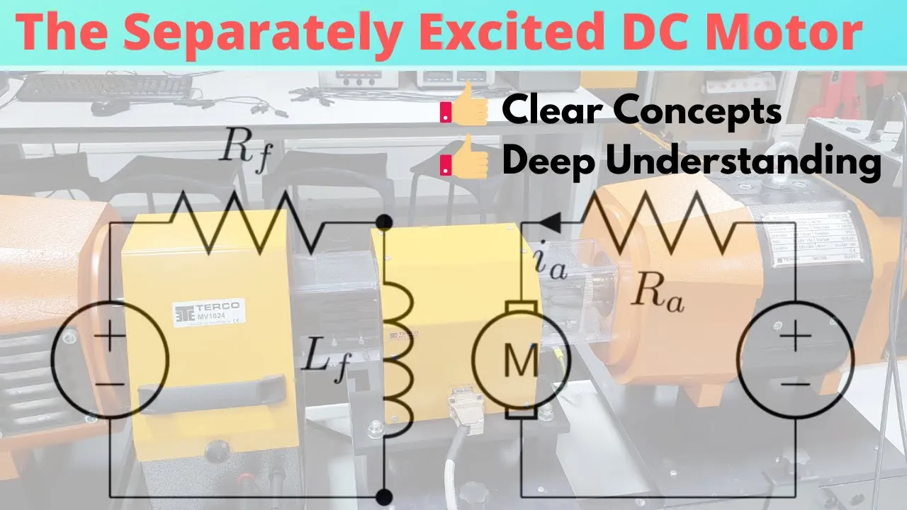
A chopper-fed DC separately excited motor uses a power electronic switch (MOSFET, BJT, or IGBT) and a free-wheeling diode to control motor speed and torque by varying the duty ratio of the chopper. In motoring operation (first quadrant), the average armature voltage VA_avg = ΔV, resulting in speed-torque characteristics that shift with duty ratio changes. In regenerative braking operation (second quadrant), the motor feeds power back to the source when the current reverses direction, achieving braking without mechanical friction. By combining these operations in a single circuit through duty ratio control, the system can achieve both motoring and regenerative braking modes, enabling four-quadrant operation for applications like electric vehicles.
Chopper Fed DC Separately Excited Motor | Electric Drives
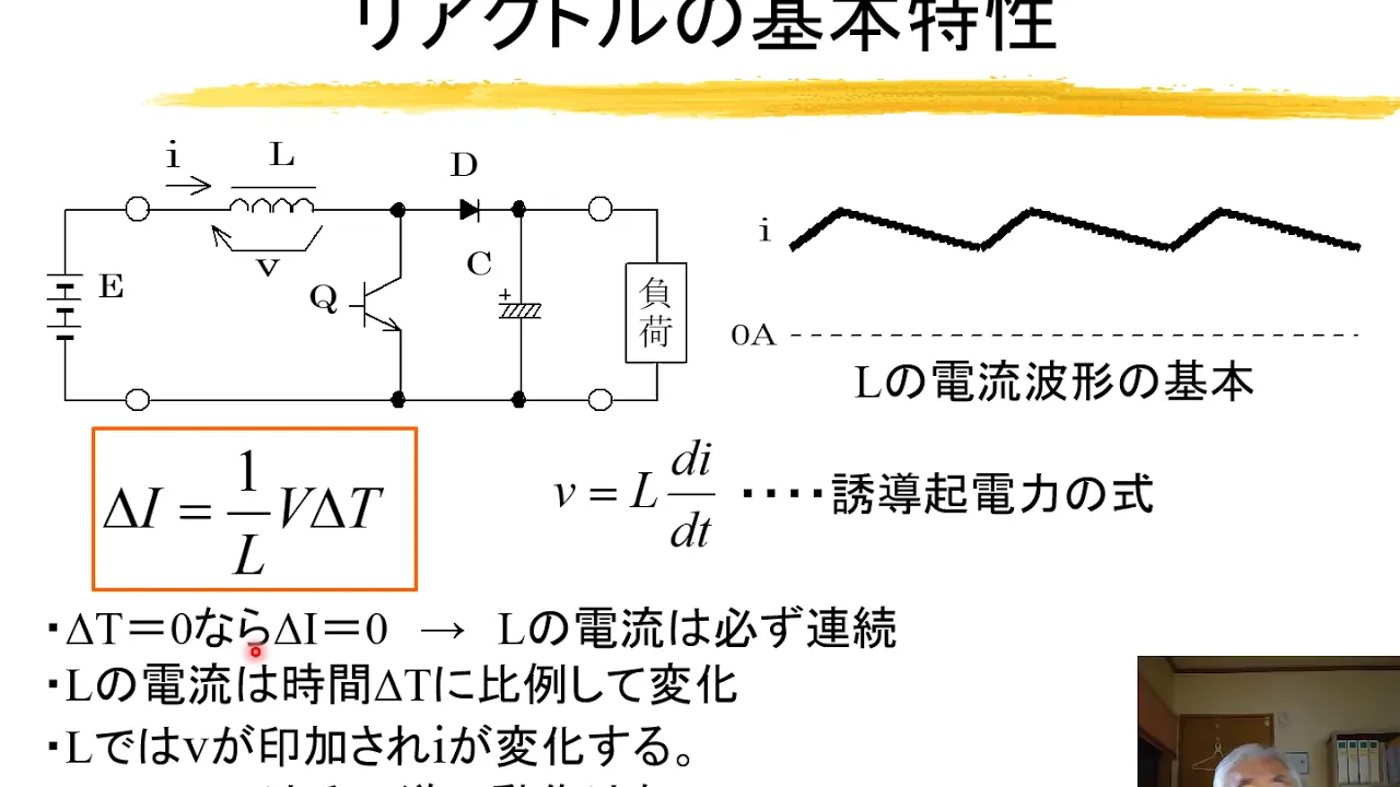
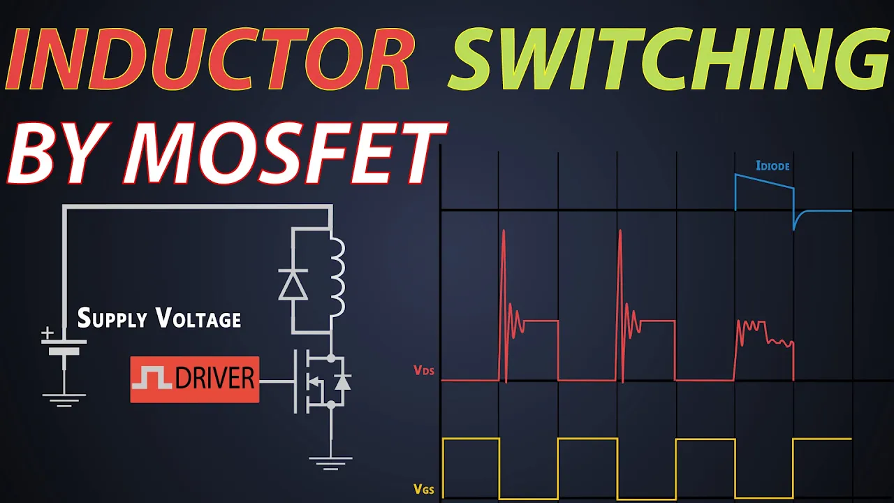
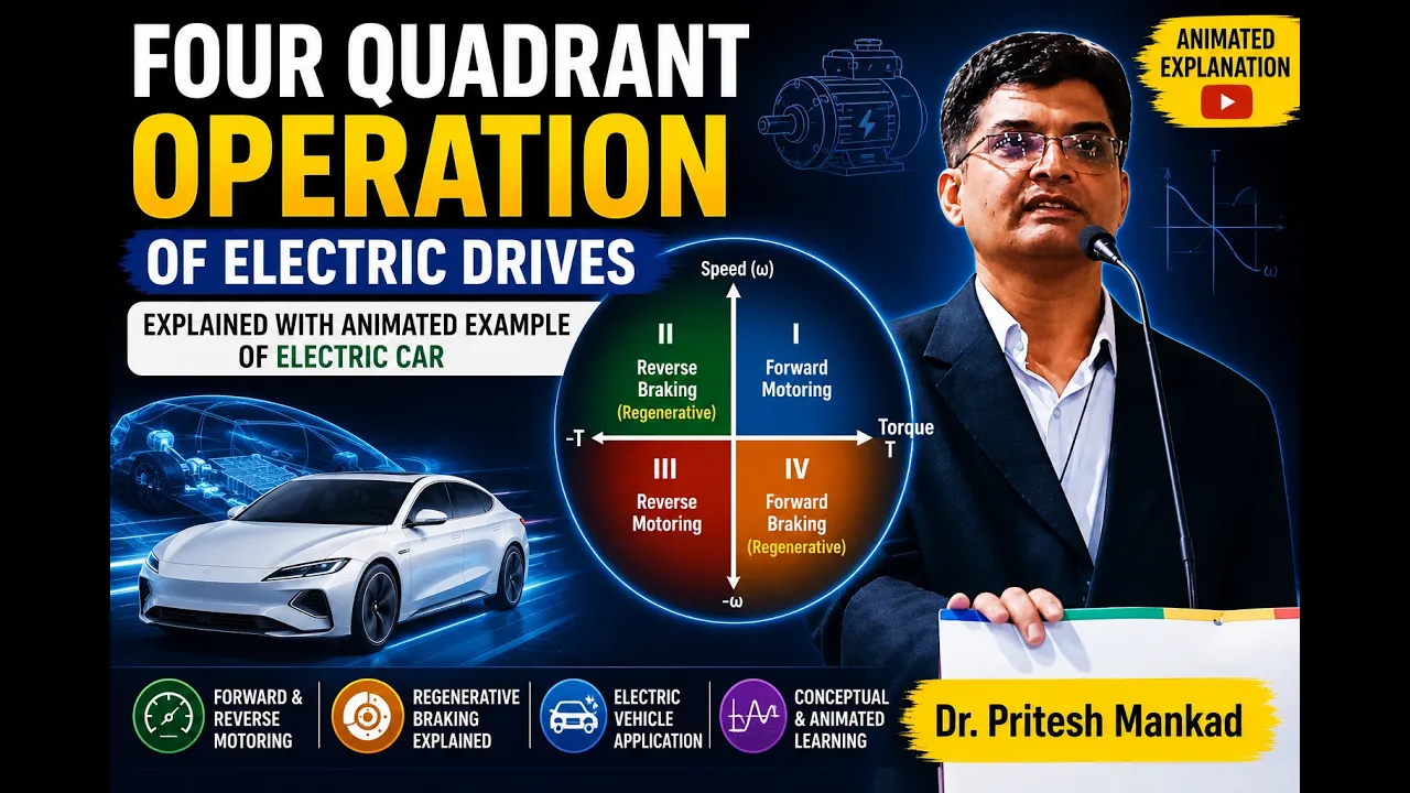
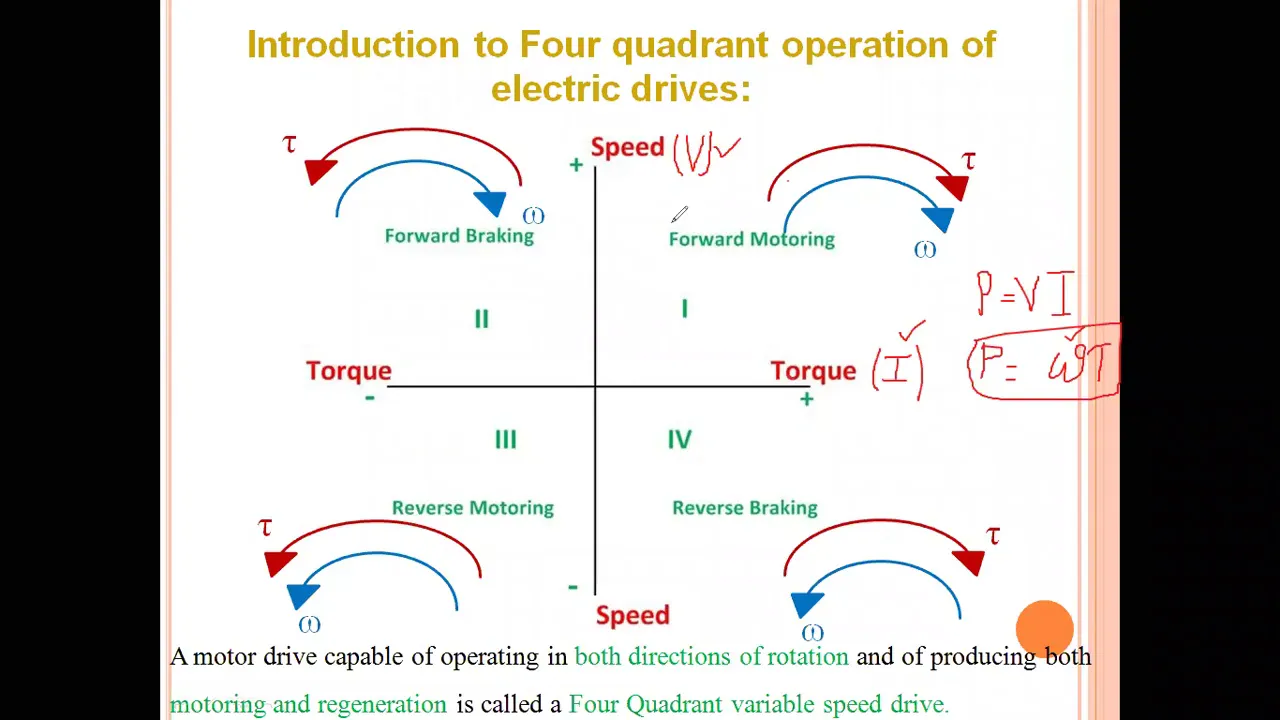
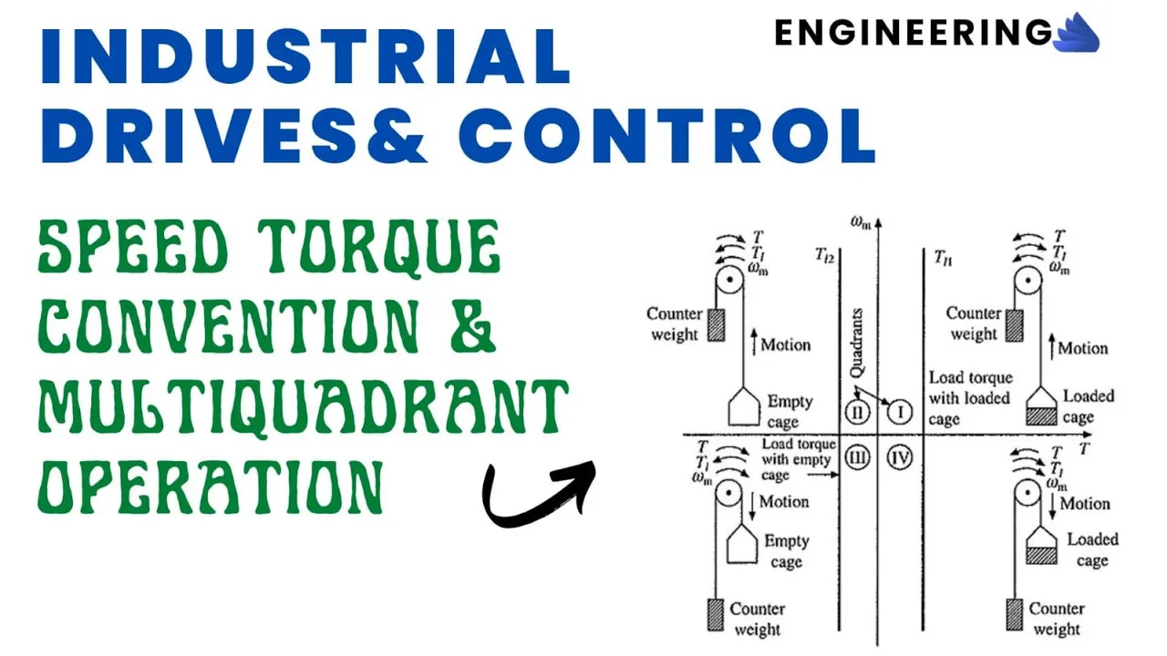
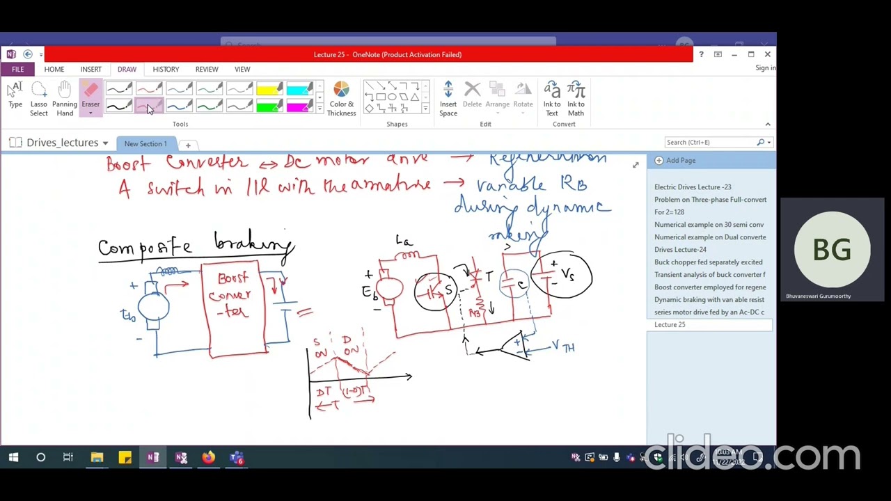
Added:foreign [Music] College so uh good morning uh my dear students so I'm taking the one of the subject uh electric Drive the kwe075 and the topic is Chopper fit control DC separately excited motor right Chopper fit DC Drive actually so in the last lecture if you have go through the last lecture we have discussed about the rectifier fit controlled uh controlled rectifier fit DC drives now we'll do the chopper fit DC drive system so there are many application of Chopper Fair DC drive system nowadays actually like because now industry is more concerned with the electric vehicles I mean all the ah kind of the fuel Motors can can converted into the electric motor so that the pollution free environment can be created so in this in this you can uh the battery for battery like the chopper fit converters is used some of the EV systems and uh it's actually basically it's used for the a switch mode power supply and so this is uh that's why this topic is very important for the for the students right and it's a chopper fit control so we're here we discuss the motoring operation as well as the braking operation then we combine these two operation with the one circuit we can we can easily get the motoring as well as the um because with the help of the Power Electronics converter now we can uh get the get the four quadrant operation or two quadrant operation in a single circuit right with the help of this switch switches availability of switches because these and these switches are based on the par the electronics um the con the mechanism is based on the and the electron the electronic space right so this is the one of the circuit that will uh this is the one of the circuit the chopper fit DC here I am using the DC separately excited motor where the flux is constant remain constant and uh this circuit we are giving the DC Supply with the help of Chopper right here we use the step down Chopper one thiester or sorry one this um switch is used it can be a mosfet or it can be bgt depending upon the application used right or depending upon the rating of the motor okay and this is one diode has been used it work as a free willing diode and the ones applied that this supplies so this circuit will operate in the giving the motoring operation and you can see it's a first one one first coordinate operation where the voltage in the current is a positive and you can say the speed and the torque is in positive right so if you see the uh the the operating principle behind it we'll just see like uh um the switch because it's a switch mode kind of converter so switch can be on or it can be off right so when the switch is on the circuit uh become like this the rest this is the model of the DC separately where the ra is the resistance of Armature winding the L is the inductance of Armature winding and the E the back EMF is which is induced in the the DC motor flux remains constant because here I am using the separately excited easy mode now with this when now to understand the operating operation of the circuit when the switch is on this switches on the circuit will become close the diode is now reverse batch because positive is giving to the the n Junction so ah it is reverse bias so the circuit carry the voltage the rest the motor and the switch so it will the current is driving the the inductor will charge and the suppose the initial current is ia1 so it will it will increases and it will go up to is2 suppose so you'll get the voltage the circuit become like this so in first mode if you see when TR is on the circuit now become carry the voltage source the whole DC motor and this is open circuit because now the diode is a reverse bias right so here the output voltage you are getting or it is called Armature voltage also you are getting the same as the the input voltage so here you can see and the voltage is connected so the the inductor will be charged so that the current will increases now I suppose the initial current is I even so during t on period when the till the the switch is on the current will rise from ia1 to ia2 and you are getting the voltage same as the input voltage that's why here it is drawing like this now the second case when this when the switch is off when the TR is off during T of period so the current which is to the which is store the energy which is stored in the inductor is released through the diode and which is in this direction because two now the diode will will become forward biased and the circuit is now it's like this only the supply is cut up from the circuit and you are getting here the zero voltage right so that's why during T of t on to T the you are getting the zero voltage and the current is now decreasing in Free Will through the diode so the current is suppose decreasing from ia2 to I A1 so this the same cycle will repeated at as the switching on Switching off process is going on so suppose the t is the time period of the circuit of the switch so now the equation become you can write the equation so if you if you're able to find out the average value so we can write the time period is 1 by T so it can be written as 1 by t 0 to T on or you can write here because because from T on to T the voltage is zero so I consider only the 0 to T on period and the voltage is the input voltage and this is we are getting t on upon t v so suppose this is called Delta B so Delta is the duty ratio and where T is the dot time period and T on is the switching on time switch on time so this is this is you are getting the voltage at the input to the supply into input to the motor now um if you see the uh the equation which is related to your motor the separately excited DC motor if you have write down the motor equation you'll see that we right so e can be written as and speed can be written as a by Phi as as you already know is equal to P Phi n by 60 into J by so speed the in radian per second can be written as K is constant and here the flux is constant so it can be replaced by like B minus V A you can write here some constantly we're considering this is suppose Ka so K is equal to KFI right now this is the simple equation which describe the relation between this the speed of the motor and the voltage the the Armature voltage in IR also and we can replace now K Phi uh as K because Phi is now constant because we are using the separately exciting motor right now uh you can see that when we use this Chopper fit DC motor now V A can be replaced by because you are getting here the voltage VA that is average value VA is now Delta V right so Omega M can be written as Delta V minus upon k for some constant k for it now uh you already know the relation between the tokens talk and the current T is equal to K Phi I a which is this equation related to your motor so it can be proportional to the talk can be proportional to k i a so this I can be replaced by T by so in this equation 1 suppose equation a I a is replaced by talk because now we have to find out the relation between the torque and speed and we'll see how the motoring operation will be fine so our aim is to draw the speed to a characteristic uh for Chopper fit uh DC drive system that's why we are getting the here we are finding the relation between the speed and torque so we're replacing i a by torque with the help of this equation right so Omega m is the speed of the rotor Delta V because you know you're repeating the voltage with the help of Chopper so it here the Delta V is there now this is IE can be replaced by so here the K and here the K Square so this is relation fine final ration will find in this way now we are trying to draw the beta characteristic and with the help of J Chopper how we'll do this all the motoring operation will be performed suppose this is torque and this is speed right so at no load at no load this term will be zero so you are getting the the no load speed will be this much right so at no load the speed will be foreign equation so you can draw the like this characteristic right correct now this is for at particular Delta value all right now when the Delta is increases uh or Delta is reduces your no load speed will get reduced so you'll get the another characteristic right when you because DC separately excited Motors generally used for the um const I mean the constant speed drive now with the help of using the chopper fit we are now getting the variable speed talk right right now you're getting the various variable speed so this is the big advantage of this circuit and uh now you're getting this kind of so as the Delta increases right and you're you're getting the positive torque right so no load speed when you are increasing the load your speed will decrease and here the Ia is positive because in this circuit you'll see the direction of the current will be like this only when the switch is on the current will flow the current will flow in this direction that is I a 1 suppose I even it is rising to ia2 because it is when the current is when the disk the device will be turn off it is Freewheel Free Will so it is like this is diode so it is free will through this and the direction of the current will be same right so the torque will be same so you're getting the I A positive current and the positive voltage and in this case you are getting the you are getting the positive current so positive torque so you speed to a characteristic will be in the clock will be in first quadrant right so here uh now achieving the motoring operation with the help of the circle right and the speed and with the help of Delta you can vary the characteristic so now the a different value of delta you are getting the different characteristics as the Delta increases this value gate increases so your characteristic will shift towards this way so this is how uh with the help of this Chopper fit you're getting the different characters different speed variations so this is the main disa sorry main advantage of this right now we're coming to regenerative regenerative Ray this is a circuit of regenerative braking how will achieve the breaking or regenerative braking with the help of the circuit right it is also the chopper fit DC Drive circuit and regenerative baking means you are feeding feeding the power from load to the source right so that it can operate the braking operation so all the energy will be ah flow from low to the source right so in this way the current is will when the current is is uh fall flowing in the opposite direction your torque will will become reversed and now the operation we perform in the second quadrant operation where the torque is negative the speed is remain the same same direction so if the Omega is positive and the torque is negative it is operate in the second quadrant operation right it is operate in the second quarter operation and uh it is performing the breaking operation and why it is regenerative because it is giving the power from feeding the power from load to the source that's why it is called a regenerative braking why breaking operation will be performed because now the current will be in flowing in the reverse Direction and the torque torque will be now negative in the opposite direction now it will perform second quarter operation so the braking operation will be found if you recall the four quadrant operation this is like first cotton suppose this is T this is uh torque this is speed so it's this first quadrant second quadrant this is circle third coordinate and this is four chord so this is forward motoring you can say these are the standard Convention of torque in the speed this is uh breaking forward breaking you can say right here the speed and the torque will both are negative so it is reverse reverse breaking sorry reverse Motoring and four quadrants record it is reverse breaking so with the help of this circuit we are achieving the forward breaking operation and why it is regenerative because it is speeding power from low to the source the current is Flowing from uh this this motor to the supply side so if the current is negative the torque is become negative but the current but the speed direction will be same so it is operating that's why it is operating in the forward breaking operation in the second quadrant now now we'll uh now we'll try to understand the operation of the operating operation of the circuit so when the Circ when the because it's a switch mode circuit so one switch is required here it can be a mosfet it can be a BJT or it can be a igbt so depending upon the what is the rating of the motor and what kind of load you are running and so and this one diode is required and this is the uh voltage source Supply DC Supply and this is a capacitor to maintain the voltage constant right now this is the model of DC motor separately excited we assume here now so it is separately accepted that's why the fluxes remain constant and we are using we are uh we are assumed that the flux is constant so this r a is the Armature resistance the winding resistance of Armature and this is the leakage reactance of the Armature this is the EMF back EMF which is induced in the Armature Center so this is the model of the DC motor right now uh when the switch is on I just make the circuit again here so that it is convenient to you foreign foreign value of the circuit this is T this is the when the switch is on foreign [Music] so NTR is on because this is blocking the current now it is reverse bias because of this Supply and the current now the when this is on circuit so the circle of big now become this way and the car this is a bag this is the back EMF so the inductor will be charged through this back EMF and the current will flow in this direction right so now the current is rising because it is charging the inductor right so suppose the current is I i1 and the current now become I A2 but during that period the voltage is zero till now suppose the voltage is zero during T to T on now after when the switch is off TR is off the circuit become because now the capacitors is sorry this inductor is charged now the current uh the energy stored in the inductor will be releasing through this diode and the current direction will be in opposite and now the power is feeding from this DC circuit to the voltage source right now the we are getting the voltage here it's equal to v v the input voltage and the direction of the current is now opposite so direction of current is all right it is in if you see previously the direction of the current is and then this side if it is a your assuming that it is a positive current so according to the taking reference that current it is the negative current right so this is the voltage again the same cycle will repeat and your current will be like this right Rising then decreasing then Rising suppose I A 1 2 between I A1 to i1 so during switch on the current will rise from IE one to ia2 and during switch off the current will decreases from IA to i1 so it is decreasing it is increasing right so this is uh this is T right so now we'll see that average value will be here also you can see this the same diagram is drawn here also right so this is the diagram same diagram is so now we'll find out the average value so here the duty ratio is T minus t on upon t so this is DT ratio Delta suppose so B is equal to 1 upon t minus t on multiply by V so it can be the T minus t on by T can be replaced by V Delta V so with the help of this if you use the same equation the same no equation the speed the characteristic taking this equation and try to put the VA value in terms of the circuit right so Omega m is equal to V minus K minus t upon K Square I here T is equal to minus k i because now the current is negative right so replace this voltage this voltage is uh yeah right U okay okay and this is T K Square R A so T can be replaced by like minus t so it can it can be a positive so if you're able to uh we are going to draw the speed talk characteristic you will see that now if you see the no load speed and the torque is zero you are getting the no lower speed will be Delta V by K with respect to T is equal to 0 at no load right so suppose the point will be here foreign now as the torque is increases because the current is now negative so it all will be negative and the overall this term will increases right so as the torque will increases the speed will getting the above the new load speed right foreign this kind of characteristic of getting and again so this is no load speed with different uh notes and this is Delta increasing foreign so here you can see that the speed is positive right but the torque is negative so torque is now we are getting the negative toss and the speed is positive because your current is now flowing in the opposite direction or it is feeding power from Source load to the source so it will creating the regenerative breaking operation because now the torque will be negative and the speed is positive right so here here getting this piece positive so at no load you will see because it's a straight line equation right so at no load T is negative so speed will be positive and you are getting the Delta V by K positive speed and as the stock load increases here speed will be above the rated speed so this kind of characteristic we are getting and these different characteristic because your Delta is varying now right at different value of delta suppose this is at Delta 1 this is at Delta 2 and this is at Delta 3. so Delta vary between 0 to 1 except DT ratio T 1 by T right so this kind of so in this mode of operation you are getting the breaking operation and regenerative rate so if you combine this two circuit in one because now in this we see that one different circuit will get the motoring operation and another circuit you are getting the braking operation region date will be if you combine this two circuit with the one whole circuit we are getting the braking operation as well as the regenerating operation by simply changing the switching of the um switches right so and this is the big advantage of the power electronic circuit based dry system because with the help of only the only just by varying the duty ratio you'll get the motoring operation as well as the braking operation right so when we combine this two circuit we'll get in a single circuit you will get you will see that the motoring and braking operation will be getting with the with only by changing the duty ratio right so we will see in the next we'll see so this is not a rectifier field this is Chopper waste so now in the next coming lecture we will see that the both we combine this both circuit and we'll see that with the single circuit we are getting the motoring as well as the regenerating operation thank you
Up Next

Hydraulic Regenerative Braking Model: A DIY Science Project
@InventorChannel2025
18.3K views•2024-07-30

Ultrasonic Transducers: Resonant Frequency Measurement and Horn Design
@imajeenyus42
229.9K views•2017-02-22

Polymer Environmental Degradation: Mechanisms & Stabilization
@iit
1.8K views•2012-07-10

How a Student's Question Saved a NYC Skyscraper from Collapse
@veritasium
22.8M views•2025-04-26
Related Study Plans & Knowledge Roadmaps
Structured learning paths in Engineering