



















A single-axis solar tracker can be built using an analog circuit with an LM324 quad op-amp configured as two comparators to compare light sensor voltages, Schmitt triggers with hysteresis to create a 'do-nothing window' for motor control, and a dusk sensor using an LDR and transistor to automatically return the panel to east position at sunset, eliminating the need for microcontrollers.
DIY Analog Solar Tracker Circuit Without Microcontroller (LM324 Op-Amp Guide)
Added:Understanding of basic Operational Amplifier (Op-Amp) theory, specifically how op-amps function as voltage comparators to compare two input signals.
Familiarity with Light Dependent Resistors (LDRs) and how their resistance changes with light intensity to create a sensor voltage divider.
Basic knowledge of DC motor operation and how polarity changes affect the rotational direction of the motor.
Ability to read electronic schematic diagrams and understand basic circuit components such as resistors, transistors, and power supplies.
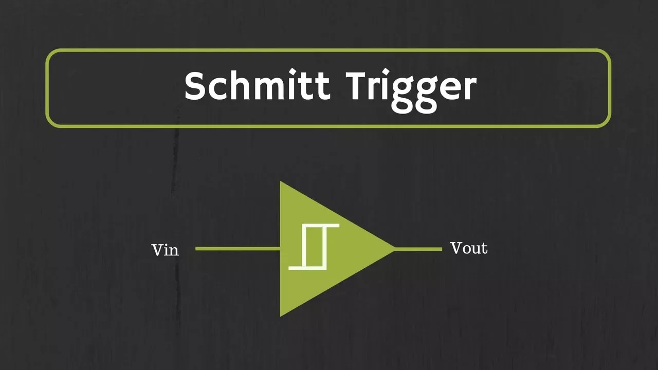
Implementing hysteresis (Schmitt trigger design) in the comparator circuit to prevent rapid motor oscillation or 'chattering' at the threshold limits.
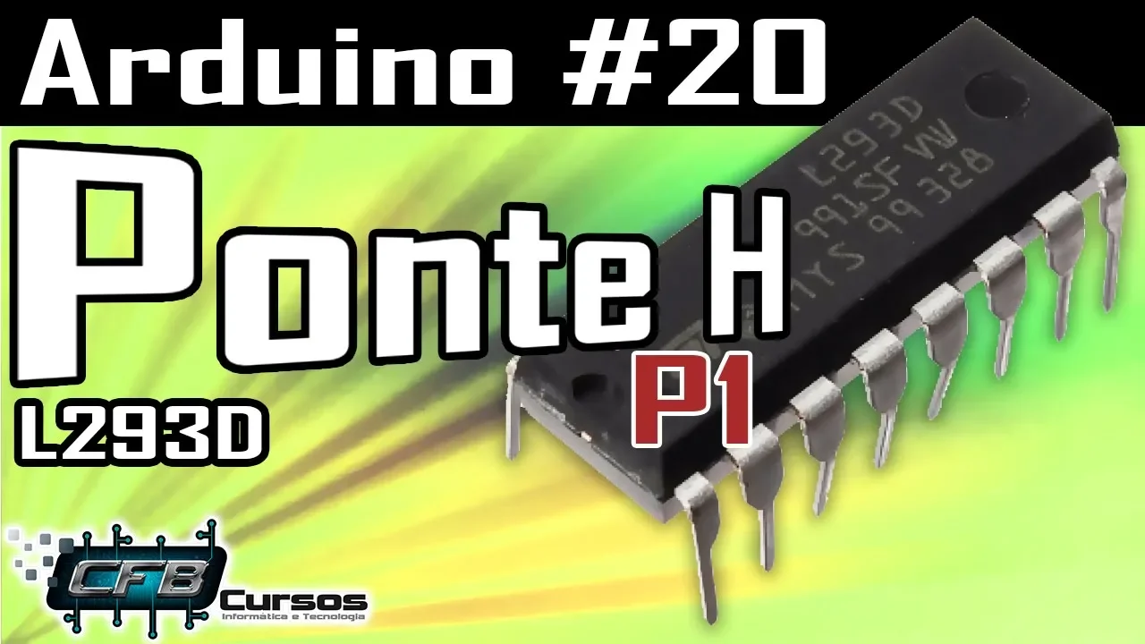
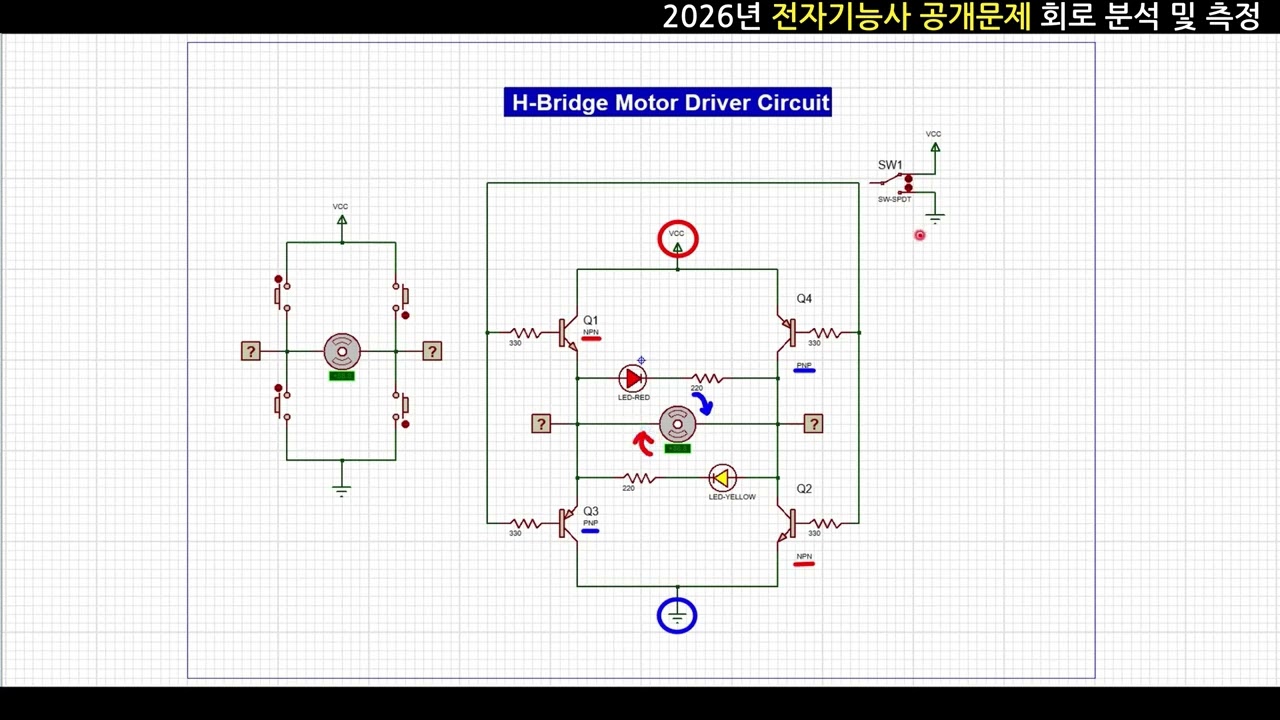
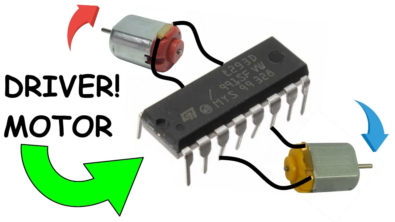
Designing a H-Bridge driver circuit using discrete transistors or dedicated ICs (like the L293D) to safely handle the motor's current demands.
Expanding the project from single-axis tracking to dual-axis tracking to account for both daily and seasonal changes in the sun's position.
Transitioning from purely analog control to digital control using microcontrollers (such as Arduino or ESP32) for features like night-return and active calibration.
3.4K views31likes29:25Original Release: 2024-01-14
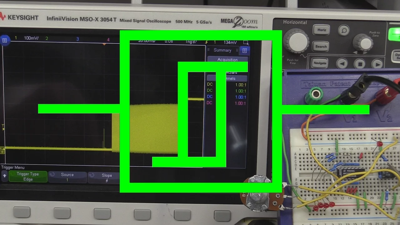
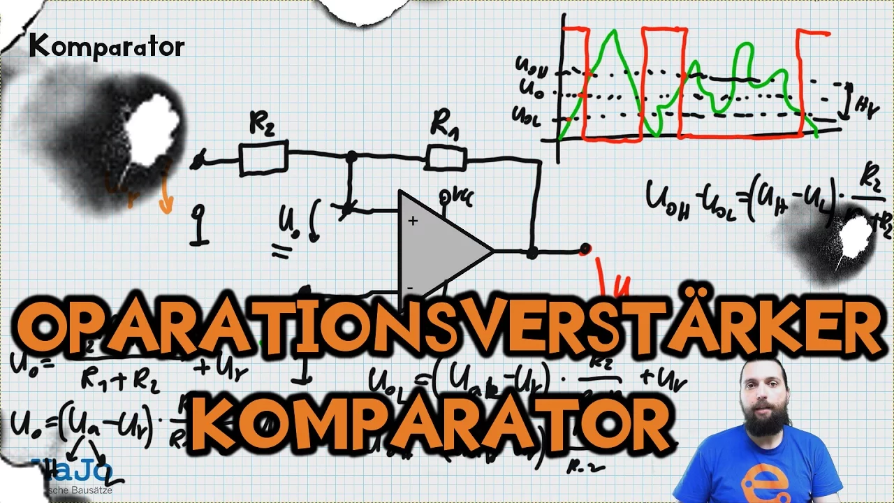
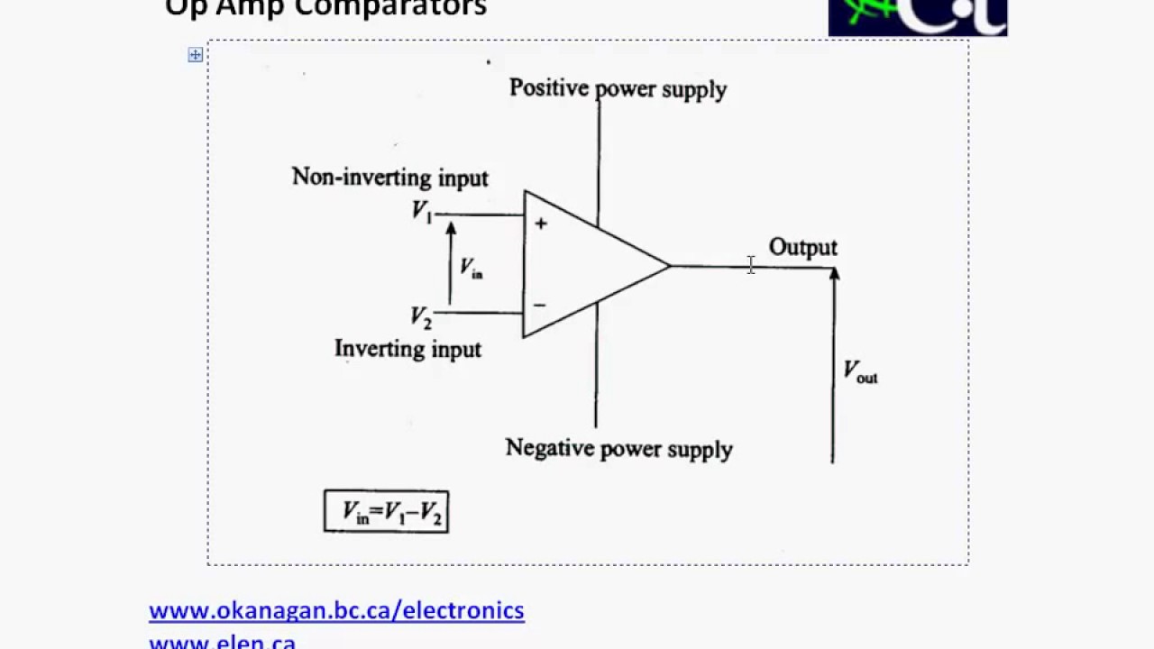
[Music] a Electronics project but before I start with my explanation here let's go outside to the yard and let me show you what all of this is actually good for so then here we are out and about it's - 7 Celsius in my part of the world and this is my homemade solar tracker which is already more than 10 years old now and it works ever since and its purpose is to charge my 12vt lead acid batteries because I have a offgrid system let me go close closer here oh so it has a slip clutch or storm clutch that's the reason why I can turn it by hand uh here in this uh aluminium box here is a geared DC motor 12vt DC motor actually a windshield wiper motor and the juice goes out through these thick wires here to my battery system and here inside this box is an arino microcontroller which does the uh tracking function which controls the geared motor in the base here is a potentiometer to adjust the offset of the thing so it is a microcontroller based tracking system and here is the actual sensor there are three ldrs inside this CH here uh one facing towards uh West one facing towards East and one facing straight forward this is for the dusk sensor so uh in the in the evening when the sun sets ah it was already moving uh in the evening when the sun sets the solar panel has to go back to East waiting for the next day and as you see here I put a strip of aluminum on the CH to cast a shadow on uh the ldrs uh it's very simple construction I cannot open it it's frozen but you get the idea A J with with three ldrs inside mounted to the solar panel itself and the solar panels are mounted to a main shaft which is in itself mounted onto a gearbox and here is the pivot point to adjust a uh elevation I do it three times a year that's enough for such a small system yeah but this is one moment this is what the uh circuit which we will build uh is good for is to control a solar tracker like this a single AIS solar tracker back at the workbench and here is uh a analog circuit which does the same thing uh controlling a motor for the solar tracker and it took me longer than anticipated to figure this all out and uh design the circuit but there we go it works and it does the job same like the uh Arduino based uh circuit okay let me explain here so we have here the um main brain of the thing which consist a um quad up amp here which I will show you in a minute in the ciruit diagram and here is the basic function uh the red LEDs show you um that both of these sensors are lit so if I cover one one LED goes out and vice versa and the other two LEDs here show uh when they relay kicks in here of my birs Nest here the relay Shield cover one side and the motor wants to uh spin in one direction to move the solar panel in between nothing happens and if the solar panel is too far off the motor wants to spin again in the other direction to uh make um correction okay and also already hooked up to the Circuit here is my dusk sensor which I also will show you in uh in a minute here on the circuit diagram uh this lets the um solar tracker going back to East when um the sun sets so I cover it up and yeah it goes back to East uh till the solar tracker reaches the limit switch and turns off the motor okay this is the complete circuit diagram of the thing but as you can already see it is a very crowded Chicken Scratch here and it barely fits on a sheet of paper that's not very very helpful that's why I will break it down to individual function blocks or sections and explain all the functions here step by step so let's start with this drawing here as I said the main brain of the thing is a operational amplifier op amp a quad op amp so this means in um this package there are four individual op amps inside it is the famous LM 324n so a very widely used uh component and I used all four of this op amps here in such a way that I use two of them as um comparators to compare a fixed voltage namely in this case 2.5 volt because I'm running the circuit here on 5 volts to compare the 2.5 volts on the fixed voltage divider here with uh the voltage divider here uh with the two ldrs which we have seen before and I'm doing this two times so uh every here inside is more or less complementary build so uh one side takes care of the voltage uh uh from 0 to 2.5 volt and the other side here takes care of the voltages uh from 2.5 to 5 volt that's why I need all four of this up amps here because I have two motor relays one for left and one for turning the motor right okay so here are two comparators to compare what's going on here and because we the operational amplifier would give out a uh voltage uh between 0 and 5 volt this would also be very helpful uh connected to the output of this uh comparator here is a Schmid trigger also on the left and on the right side which I can show you here on the other drawing let's bring in this one here okay so this is one half of the LM 324 here I have the two ldrs I have a potentiometer to make some fine adjustments uh to get the offset right here is the comparator with the fixed voltage divider and a little bit of feedback here from the output to the uh inverting input and the output of this comparator here goes to a uh Schmid trigger which uh turns on at roughly um 3 volts and turn off at one volt so we have a window in between where nothing happens also important to note that I don't use the same values you see it here on one of the Schmid triggers I have a 13k uh feedback resistor and on the other schet I have a 36k feedback resistor to VCC because I need a window so to speak a do nothing window I call it do nothing window hysteresis where nothing happens so the motor needs uh some leeway between turning the solar panel to the right or to East or to the left or to West and I'm achieving this by simply using different values on the feedback resistor here and also here at the uh non-inverting input here my dusk switch feeds in and lets the motor spin to East when uh this the sun sets Okay so here again I have here is the the comparator circuit very simple comparator as I said a fixed voltage divider on the inverting input and a voltage divider of two ldrs in a pot on the non-inverting input this one feeds in like so to the inverting Schmid trigger which as I said the trigger low is one Vol and the trigger high is 3 volt there is some uh hysteresis in between okay I hope this was conclusive so far and coupled to this uh operational amplifier here is a relay Shield I call it again and we need one PNP and one can can we see this here on camera we need one PNP and one npn transistor because uh one of these outputs uh will source and one will syn and as you see here we have a limit switch which um turns off the relay once the left or the right or should I say the limit West or and the limit East is reached just a little normally closed switch here and here comes the last part of the circuit which is also crucial because uh your solar panel needs to go back to East waiting for the next morning and it does this uh when the sun sets as I said and it is a a very very simple uh dusk sensor dusk switch circuit based on a an PN transistor and ldr a little bit of filtering here and a potentiometer to F adjust the thing and it pulls um where is it and it pulls the input here and it pulls this input here low like so if that makes sense sooo this took me quite a bit of time to get my head around it and to figure all the values out and um yeah get the function right as I said here is the complete circuit dusk sensor the ldrs East and West the ldr for dusk here is my operational amplifier with the voltage divider here here and here one 121 voltage divider and this section here is the Schmid trigger here and here I have LEDs which show me uh the state of the thing here so the red ones which show me the how much uh light is getting to the ldrs and this two green ones they show me uh which um relay is on or which output is currently on and here is my relay AG Bridge very simple AG Bridge the usual stuff here and here is the connected the DC motor I added a 5vt voltage regulator to feed the whole circuit here it runs on 5 volt so you can uh run all this circuit here with voltages somewhere between 6 and 30 volts depending on what kind of motor you're using on your solar tracker okay here again my circuit and I solded up this monstrosity because I had a lot of problems with flaky contacts here on my breadboard because here an operational amplifier has a very high gain okay so here is are my two ldrs again one facing towards West and one facing towards uh East here is my adjusting pot so that I can make some fine adjustments if uh it is off a little bit and notice what happened on the red LEDs one is gradually fading out and one stays lit so it shows me which ldr got more light than the other one and the green ones they are connected to the Schmid trigger so they have um some uh hyeres where they ignore all the fading here from this L this LEDs here and at a certain point the relay kicks in the motor drives the solar panel and it turns off and if the solar panel is off in the other direction the other relay kicks in the motor turns the solar panel and turns off the relay so there is some leeway in between where the solar panel is perfectly aligned with the Sun so that explains this one the main brain and here is my not very complex uh relay Shield here on a RedBoard two transistors two 5vt uh relays some filtering and there are no motor um cables connected now to the relays because it's just for testing purposes here but most of them work and none of them is on and here is the circuit The Dusk sensor again a ldr two resistors a uh transistor and a capacitor for extra filtering and here is another potentium meter where I can find adjust one in the evening the solar panel uh turns back to uh its starting point so to East fin a trust yeah so if I covered it wait a minute there a sheet of paper here does it work yeah so if I cover the dusk sensor uh meaning it's dark outside uh the circuit no longer reacts to these two alar and keep spinning until the uh end switch is reached and the next morning the cycle can start over again so yeah I think now it's time to uh make all of this into a functional and usable circuit board this time it will be a single sided PCP and the first step is to find the locations for the connectors the screw terminals here and the relays the choose comes in here plus and minus uh here uh will be the motor connected motor H Bridge fuse for the motor fuse for the uh rest of the electronics limit switches and connectors for the ldrs well let's hold this up and here comes the usual disclaimer because I have to say this over and over again I am not an expert I am an uneducated hobbyist I build stuff which works in the end at least for me so if you find some design flaws in my uh drawings or in uh my finished projects here feel free to do a better job what I'm doing here on YouTube is uh sharing my learning experience with the world I am experimenting a lot and I'm enjoying the time hanging out with you here in the shop and if you want to support me you can leave a like subscribe or even become a patreon if you want to if you want to spend a buck or two this would be [Music] helpful [Music] finally after a couple of hours and a lot of swearing here we are with the final product the finished circuit board and I squeezed everything on to this uh perf board here it is a wild mix of thr hoold components and SMD components uh mainly most of the resistors are SMD resistors here it's the 12 06 package and also some capacitors here and uh the reverse protection here diode all than that this is exactly the same as you have seen on the uh monstrosity this one here and it works obviously exactly in the same way here is my uh dusk sensor here are the two sensors for East and West here are the uh end or limit switches which are I bridged with wires to test the thing uh linear voltage regulator 5V fuse for um the secetary a fuse for the motor H Bridge H Bridge driver transistors um the offset pot for East and West and the adjusting pot for the dusk sensor my red LEDs my GRE green LEDs which uh show me indication which uh releas relay is on yeah the edge Bridge here the usual stuff so I would say let's hook it up and give it a try fumble fumble so I hooked it up to my benchtop power supply here 12 Vols and because I have multiple light sources in here I also put a torch here on my workbench to simulate uh natural sunlight here from one light source and basically all you have to do is to um align your uh sensors here directly to the Sun or to the uh light source and trim the pot to a point where these two red LEDs here or you can choose any color you want uh I illuminated uh roughly the same and that's all you have to do and now if I turn it one Fades away and one relay kicks in the motor does it thing and goes off again if I turn it the other away the motor kicks in it goes off again and here is the function of the dusk sensor cover the dusk sensor and no more reaction here so the motor is spinning and spinning and spinning uh to the point where this contact UM gets opened and obviously the motor stops there and let's have a look at the coent current which could be also a critical point so when the relays are off so the speak when the solar panel is perfectly aligned to the sunlight we have here 20 milliamp at 12 vol and let's create an offset to turn on one of the relays here now we are talking about 80 milliamps on 12vt so still under 100 milliamps so I would say this circuit is also suitable for very small offgrid systems with a small battery and a small solar [Music] panel that's fun so then since the video is already way too long I will wrap it up here and if you found the video somewhat entertaining or interesting please give me a like subscribe to my channel leave me a comment if you want you can also visit me on the patreon.com larifari or on instagram.com larifari YouTube uh I will will post the full circuit diagram onto my Pinterest profile as well as onto my patreon profile and so far I say follow the [Music] sunshine
Up Next

14:38
Hagia Sophia Structural Genius: Byzantine Architecture Explained
@ManuelBravo
114.3K views•2021-07-15

30:32
Ultrasonic Transducers: Resonant Frequency Measurement and Horn Design
@imajeenyus42
229.9K views•2017-02-22

54:16
Polymer Environmental Degradation: Mechanisms & Stabilization
@iit
1.8K views•2012-07-10

33:39
How a Student's Question Saved a NYC Skyscraper from Collapse
@veritasium
22.8M views•2025-04-26
Related Study Plans & Knowledge Roadmaps
Structured learning paths in Engineering
engineering
Building Acoustic Levitators: Physics & Arduino
01The Physics of Sound and Standing Waves
02Piezoelectric Transducers and H-Bridge Drivers
03Arduino Programming: Generating 40 kHz Signals
+ 2 more learning modules
14h5 modules
Explore Roadmap
engineering
Building Peltier Cloud Chambers: Particle Tracks
01Cosmic Rays & Cloud Chamber Physics
02Thermoelectric Cooling (TEC) Fundamentals
03Custom Liquid-Cooling Loop Design
+ 2 more learning modules
18h5 modules
Explore Roadmap
engineering
Yagi-Uda Antennas: Modeling, Build & VNA Test
01Introduction to RF and Antenna Fundamentals
02Yagi-Uda Antenna Design Principles
03Antenna Modeling and Simulation in 4NEC2
+ 2 more learning modules
18h5 modules
Explore Roadmap
engineering
ECG Monitor Design: Op-Amps, Filters & Noise
01Electronics & Breadboard Basics
02Op-Amps and Instrumentation Amplifiers
03Bioelectricity and ECG Fundamentals
+ 2 more learning modules
18h5 modules
Explore Roadmap