A 3D printed snake robot body consists of modular parts (head, body sections, and tail) connected through linkages, with a flexible joint design allowing loose connections for natural snake-like movement; the body parts are designed in CAD software like FreeCAD and assembled using simple components like safety pins as spacers and screws for connections.
Designing a 3D Printed Snake Robot: Body and Mechanics
Added:Deep Dive
Basic proficiency with parametric CAD software, specifically navigating FreeCAD, sketching, applying constraints, and creating 3D solids.
![01-[Tutoriel] FreeCad, Les Bases pour bien débuter.](https://i.ytimg.com/vi/SPFoXfEAufw/maxresdefault.jpg)
01-[Tutoriel] FreeCad, Les Bases pour bien débuter.
504.2K
FreeCAD is a free parametric CAD software where users create 3D models by defining functions with adjustable parameters that can be modified at any time, allowing the entire model to automatically update; the basic workflow involves creating 2D sketches on planes (like XY plane) using tools such as circles, then extruding these sketches along an axis to generate 3D solids, with camera navigation controlled through mouse buttons and numpad keys for viewing different perspectives.
Click to watch →

FreeCAD 1.0 Ultimate Beginners Crash Course in 1 hour for 3D printing CAD Lesson / Tutorial
366.8K
This comprehensive section covers the foundational skills needed to begin using FreeCAD effectively. Topics include downloading and installing FreeCAD from the official website for Windows, Mac, or Linux platforms. Initial setup covers language selection, units configuration (metric/imperial), navigation style preferences, and theme customization. The interface overview introduces workbenches as specialized tool collections, with Part Design being ideal for beginner-friendly parametric modeling. Key interface elements explained include the 3D view for model creation, model pane showing document structure, and task pane for operation parameters. 3D navigation techniques are covered in detail including touchpad and mouse controls, with core shortcuts for zoom, rotate (Alt+drag with pink center indicator), and pan (Shift+drag). The coordinate system display and 3D cube for view selection are also demonstrated. The section concludes with body creation fundamentals, where each part exists within a container body visible in the tree view, and origins can be shown/hidden. Sketch creation involves attaching to planes (XY, XZ, YZ) using the sketch icon, with View > Sketch orienting the view perpendicular to the selected plane. Geometry drawing uses cursor coordinates for precision, with Tab cycling through dimension fields. The critical concept of fully constraining sketches to zero degrees of freedom is introduced, with constraints including symmetry, coincident, and combined constraints. Under-constrained sketches appear red and behave unpredictably, while fully constrained geometry turns green.
Click to watch →

STOP using FreeCAD WRONG! Do this INSTEAD (Workflow & Tips)
38.7K
The Sketcher is considered the foundation of everything in FreeCAD. Unlike direct modeling software like Blender where you pull and move points, FreeCAD is driven by dimensions and constraints. Everything is controlled parametrically, meaning users must have a two-dimensional vision of their object before creating it. This sketch-first approach transforms 2D drawings into 3D solids using either the Part Design or Part workbench.
Click to watch →
FREECAD - AULA 01
22.2K
This tutorial introduces FreeCAD, a free parametric 3D CAD modeling software, demonstrating how to create a 2D sketch by drawing lines and applying geometric relations (like vertical/horizontal alignment and coincidence) and dimensional constraints (such as 25mm width and height) to create a fully constrained triangle, then extruding it into a 3D object and creating a hole using the pocket tool with dimensional specifications.
Click to watch →

FreeCAD vs Onshape vs Plasticity - How to Start 3D Modeling for 3D Printing?
957
This comprehensive section covers FreeCAD's core parametric workflow. Users learn to create 2D sketches on coordinate planes, apply dimensions and geometric constraints to achieve fully defined geometry, and use pad/pocket operations to build 3D solids. The feature tree/history records every operation, enabling modification of previous steps with automatic regeneration. Advanced topics include creating sketches on solid faces using external projection, converting reference geometry to construction lines, applying symmetry constraints relative to planes, and managing multi-stage solid construction. This systematic approach ensures design consistency but requires careful initial constraint setup.
Click to watch →
Deep Dive
Understanding of 3D printing design rules (DFAM), particularly design tolerances, clearances for interlocking/moving parts, and material shrinkage.

4 Keys to Make Your 3D Printed Mechanisms Work First Time
19.6K
3D printing cannot achieve the micrometer-level accuracy of machining; instead, it builds parts layer by layer with inherent dimensional variability. To compensate, designers must leave gaps between interacting faces—typically 0.2mm as a baseline. However, gap sizing depends on print orientation: parallel-to-bed features are most accurate and strongest, allowing smaller gaps, while perpendicular orientations introduce layer line variability requiring larger tolerances. Overhanging features need even more clearance due to potential drooping. For simple parts, gaps as small as 0.075mm work; for complex overhangs, 0.4-0.5mm may be necessary. Moving parts require additional clearance for wear. Understanding these relationships between design intent and manufacturing reality is essential for functional 3D printed mechanisms.
Click to watch →

Design enclosures for electronics (using mechanical mindset)
34.9K
Reliable 3D printing requires following established rules of thumb for mating fitments, text, and angles. Design with 0.3mm clearance in each dimension to account for printer deviations - a 20mm female part should be 20.6mm to accommodate 0.3mm tolerance on each side. For text and labels, use debossed fonts (not embossed) with at least 0.5mm depth, avoiding serif fonts that don't print well. Recommended: DSO bold font at 6mm height, 6mm from base for repeatable orientation verification. Apply 2° draft angles as a starting point, recognizing that deep-drawn parts have inconsistent wall thickness requiring extra margin. These conventions enable consistent results across different printers and operators.
Click to watch →

Introduction au DFAM (Design for additive manufacturing)
6.2K
This segment addresses the critical topic of dimensional tolerances in 3D printing. The instructor explains that printed parts require dimensional adjustments due to printer accuracy limitations. For less precise printers, you may need to add 0.2mm to 0.4mm of tolerance to ensure parts can be assembled. For more precise printers, smaller tolerances (0.1mm) may be sufficient. The instructor demonstrates how to adjust tolerances by modifying the dimensions of threaded surfaces using the push/pull tool, and explains how to verify the results using the section analysis tool.
Click to watch →

Fusion 360 for 3D Printing LESSON 18: Metrology and Design Rules for 3D Printing
6.3K
Different joint types require different tolerances for successful assembly. Axle joints (moving parts like wheels) need tolerance for smooth motion without wobble or friction. Snug slip fits (like eyeglass cases) need tight tolerances for secure hold while allowing removal. Compression fits (permanent assembly) require negative tolerance where pins are larger than holes. Additionally, 3D printers cannot print over air without support, so maximum bridging distance must be determined. These tolerances ensure functional assemblies that meet design requirements.
Click to watch →

Design Rules for 3D Printing Part 1
1.3K
This video presents essential design rules for FDM 3D printing: walls must be at least 0.8mm thick (2 layers), embossed/engraved details require 0.6mm width and 2mm height, holes need minimum 2mm diameter, moving parts require 0.5mm clearance, minimum feature thickness is 2mm, pins need 3mm diameter, and hobbyist printers have ±0.5% tolerance requiring holes to be slightly larger than pegs.
Click to watch →
Deep Dive
Fundamentals of rigid body mechanics, including degrees of freedom (DoF), revolute joints, and basic linkage mechanisms.
Understand revolute joint and how it affects the degrees of freedom in a system
7.3K
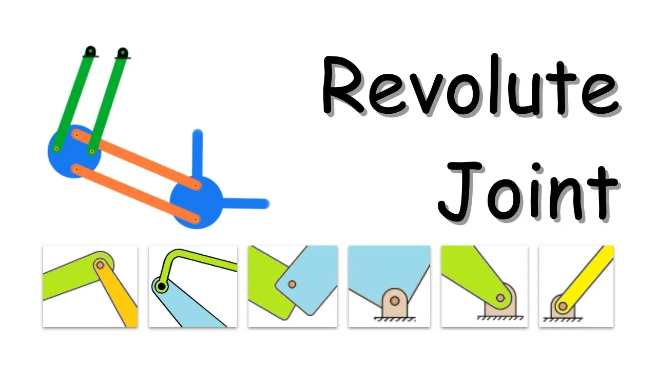
A free rigid body in 3D space has six degrees of freedom: three translational (x, y, z) and three rotational. When constrained to a 2D plane, it loses three degrees of freedom, leaving three (x, y, and rotation). For multiple rigid bodies, total DOF equals 3 times the number of bodies. Kinematic joints constrain motion; specifically, a revolute joint (pin/hinge) eliminates two translational DOF while permitting one rotation between connected bodies.
Click to watch →

Machine Mobility
109
Mechanics divides into statics (bodies at rest, F=0) and dynamics (moving bodies, F=ma). A rigid body undergoes no deformation (delta=0, elastic modulus=infinity). Motion types include translational (point to point), rotational (around axis), and complex motion (combination). Kinematics studies motion parameters without forces; kinetics studies forces causing motion. A mechanism is a collection of links connected through movable joints where parts move relative to each other without energy transfer. Links are rigid, flexible (deform but transmit force), or fluid (transmit pressure). Joints connect links and enable relative motion. Lower pairs have surface contact (revolute, prismatic, screw joints), higher pairs have point or line contact (cam, gear joints). Constraints reduce degrees of freedom: completely constrained (predictable motion), incompletely constrained (uncertain motion), successfully constrained (controlled motion). A body in free space has 6 DOF (3 translational, 3 rotational); a body on a 2D plane has 3 DOF. Gruebler's equation calculates mechanism mobility: M = 3L - 2J1 - J2. Joint order equals number of links minus one on that axis. A mechanism forms when a kinematic chain becomes completely constrained by fixing one link as ground.
Click to watch →
Mechanical Design (Part 5: Four Bar Linkage)
124K
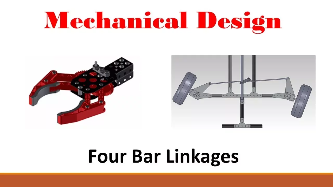
Degrees of freedom refer to how much movement an object can have, specifically the number of independent parameters that define its configuration. A rigid body has six degrees of freedom: three translational movements (up-down, left-right, front-back) and three rotational movements (yaw, pitch, roll). These correspond to movement along the X, Y, and Z axes plus rotation about each axis. This concept applies to all rigid components in mechanical systems, including links, joints, and entire mechanisms.
Click to watch →

Nguyên lý máy - Tuần 1 - Chương 1: Cấu tạo cơ cấu
22.2K
This comprehensive section covers the foundational concepts of mechanism analysis. A rigid body in a plane has 3 degrees of freedom (DOF): two translational movements along x and y axes, and one rotational movement around the z-axis. A rigid body in space has 6 DOF: three translational movements along x, y, and z axes, and three rotational movements around these axes. A link (khâu) is a generalized concept representing a rigid body that can move relative to other bodies, classified into rigid links, flexible links, and fluid links. A joint (khớp) is the connection point between two links that allows relative motion, classified by DOF constraints (Joint types 1-6) and contact type (lower pairs with surface contact, higher pairs with point/line contact). Specific joint types include spherical joint (surface contact, constrains 3 DOF), cylindrical joint (line contact, constrains 2 DOF), revolute joint (surface contact, constrains 5 DOF), and screw joint (surface contact, allows coupled rotational and translational motion).
Click to watch →

درس الروابط الميكانيكية
38.4K
A mechanical link is a relationship between two parts that constrains their relative movements, characterized by the number of degrees of freedom (DOF) it allows. A free body in 3D space has 6 DOF: 3 translational movements (along X, Y, Z axes) and 3 rotational movements (around X, Y, Z axes). The three basic mechanical links are: (1) Fixed link (رابط الارتكازي) - allows only 1 DOF (rotation around one axis), preventing all other movements; (2) Sliding link (رابط الانزلاقي) - allows only 1 DOF (translation along one axis), preventing all other movements; (3) Welded link (رابط الاندماجي) - allows 0 DOF, completely joining two parts as one unified body.
Click to watch →
Deep Dive
Familiarity with standard mechanical hardware, such as threaded fasteners, bearings, and pins used to join mechanical components.

CLASS - 31 | बन्धक | Fasteners | Diesel Mechanic Full Course | NMDC Vacancy 2021
24.2K
Fasteners (बंधक/फास्टनर) are mechanical devices used to join machine parts during assembly. They are classified into three categories: (1) Temporary Fasteners - used when parts need frequent disassembly, such as pins and press fit joints; (2) Semi-permanent Fasteners - used when occasional disassembly is needed, such as rivets and welding; (3) Permanent Fasteners - used when parts should not be separated, such as welding and soldering. Pins are classified into three main types: (1) Key Pin - requires slots in both hub and shaft; (2) Spline Pin - requires slots only in hub; (3) Spline Key - requires slots only in shaft. The spline key has a special head design with a chamfer angle of 30 degrees to facilitate easy removal. Plain pins are cylindrical fasteners with three main specifications: length, width (diameter), and thickness. They are typically made of 220F material with hardness of 1200. Round pins have a circular cross-section and are installed by cutting slots in the parts being joined. Cotter pins are classified into three types: (1) Flat Cotter - used for light-duty applications; (2) Tapered Cotter - used for medium-duty applications; (3) Tapered Cotter with Head - used for heavy-duty applications. The flat cotter is installed by cutting slots in the parts and bending the pointed end. The tapered cotter provides better fit and holding force. Tapered coppers are commonly used in rolling mills, installed at 120 degrees on wheel periphery.
Click to watch →
Fasteners and Thread Standards (KQ10)
3.7K
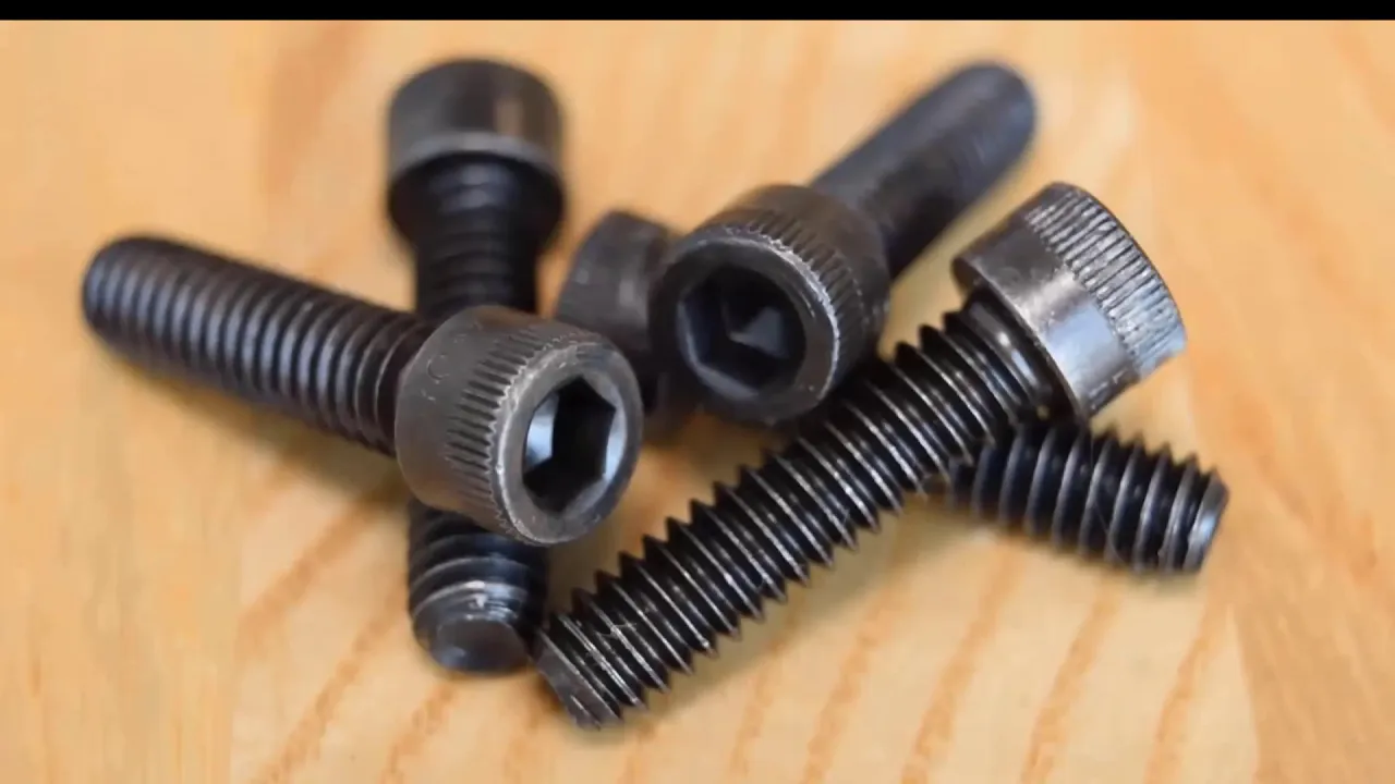
Mechanical fasteners are critical design elements, with a Boeing 747 containing 6 million parts, half being fasteners. They divide into permanent (welding, gluing, riveting) and non-permanent (bolts, screws, studs). Threaded fasteners are most widely used due to reusability. Common types include hex head screws (most common), socket head screws (tight spaces), button heads (electronics), and flat head screws (countersunk). Materials range from low-carbon steel to titanium, inconel, and plastics. Zinc plating is economical for dry environments; chromate coating offers better corrosion resistance. Standards include ASTM, NAS, AAS, SAE for US fasteners and ISO/DIN for metric. Higher grades indicate higher tensile strength. Coarse threads (UNC) are standard; fine threads (UNF) offer 10% strength increase and vibration resistance. Thread engagement of 2x nominal diameter is sufficient.
Click to watch →

L16 standard components
1.6K
Fasteners are mechanical devices with spiral threads that work in pairs (bolt and nut) to join components together, where the bolt's external threads mate with the nut's internal threads through profile matching rather than interference fit; metric screw threads follow a 60° triangular profile standard, with the nominal diameter referring to the outside diameter, and proper clearance (typically about 0.5mm) is essential for assembly; various locking mechanisms including locking nuts, nylock nuts, spring washers, castle nuts with split pins, keys for preventing rotation, and circlips for axial positioning are used to prevent loosening and ensure secure connections in mechanical assemblies.
Click to watch →

بكالوريا 2024: بداية تعلم الرسم من الصفر مع مفيد🔥💯🧑🏫 الحلقة الأولى..أرواح تفهم الهندسة الميكانيكية
49.5K
Mechanical assemblies use various fasteners and retainers to secure components: shoulders (الكتف) are created by increasing shaft diameter, flat washers (الجاف) provide axial support, lock washers (حلقه مرينه) prevent loosening, set screws (صموله محزز) secure components, and cotter pins (سي بون) lock parts in place. These components are mounted on shafts and housings with specific conditions depending on whether the shaft or housing rotates. Understanding which components rotate is essential for proper retainer selection and placement.
Click to watch →

Conversando sobre mecânica - o que um mecânico deve saber?
2.3K
Mechanical technicians must thoroughly understand machine components including fasteners (bolts, nuts), washers, bearings, shafts, bushings, couplings, and various joints. Critical distinctions exist between similar components—for instance, washers versus spring washers (mushroom washers), and right-hand versus left-hand threaded fasteners. Incorrect fastener selection based on thread pitch (e.g., M12x1.75 vs. M12x1.25) can cause component failure. Comprehensive knowledge of these elements enables proper machine assembly, disassembly, and repair.
Click to watch →
Prerequisite Knowledge
- Concept 01Basic proficiency with parametric CAD software, specifically navigating FreeCAD, sketching, applying constraints, and creating 3D solids.
- Concept 02Understanding of 3D printing design rules (DFAM), particularly design tolerances, clearances for interlocking/moving parts, and material shrinkage.
- Concept 03Fundamentals of rigid body mechanics, including degrees of freedom (DoF), revolute joints, and basic linkage mechanisms.
- Concept 04Familiarity with standard mechanical hardware, such as threaded fasteners, bearings, and pins used to join mechanical components.
Subsequent Learning
- Step 01Selection and integration of actuators (such as RC servo motors) and electronic controllers to drive the snake's joint segments.
- Step 02Study of biomimetic robotics and gait design, learning how to mathematically model and program snake-like locomotion (e.g., lateral undulation).
- Step 03Implementation of forward and inverse kinematics to control the exact spatial positioning of the robot's head and body segments.
- Step 04Integration of sensors (such as IMUs or distance sensors) to enable closed-loop feedback control and obstacle avoidance in physical environments.
Design & Parts
Body Assembly
Circuit Plan
Design & Parts
0:00Playing Section
- 1
Presents the 3D-printed snake robot components designed in FreeCAD.
- 2
Explains how the head, body, and tail sections fit together with clips.
- 3
Shows a flexible body structure using linkage joints and printed parts.
Soft Robotics and Continuum Mechanics
An alternative paradigm to rigid, segmented 3D-printed snake robots is soft robotics, which utilizes continuous, elastomeric bodies actuated by pneumatics, hydraulics, or tendon wires. Critics of rigid segmented designs argue that traditional mechanical joints introduce high friction, physical complexity, and susceptibility to environmental hazards like dust, water, and debris, which can easily damage or seize 3D-printed components. In contrast, soft continuum robots offer inherent compliance, continuous deformation, and superior resilience in unstructured environments. By eliminating discrete mechanical hinges, soft snake robots can safely deform around obstacles, squeeze through highly confined spaces, and survive impacts that would fracture rigid plastic linkages. This opposing approach shifts the design challenge from mechanical joint assembly to material science and the complex control algorithms required for non-rigid bodies.
Deep Dive
Selection and integration of actuators (such as RC servo motors) and electronic controllers to drive the snake's joint segments.

Es fährt! - SunFounder Video Car (Teil 2) | TechKarton (German)
1.8K
This segment covers the integration of servo motors and their connection to the servo controller. Shorter cables connect to the servo controller: black cable to upper row leftmost position then to port 2, white cable to port 2 in second row, gray cable to port 1. The left servo motor connects to the upper port for tilt control, while the right servo motor connects to the lower port for rotation control. The servo controller connects to the motor controller using blue and black cables to the outermost port, then to the second block from the right. The dark blue cable connects to port 1 and then to the leftmost port.
Click to watch →

УАЗ "Буханка" Радиоуправляемая модель. Часть 4
72.9K
This segment covers the process of selecting and modifying a servo motor for RC model steering. The selection process involves considering the scale and weight of the model, choosing servos with metal gears for durability, and ensuring the servo fits within the available space. If the servo is too tall, modifications include cutting the bottom of the housing and shortening the mounting screws. The segment also covers testing the servo's range of motion, which should exceed 180 degrees for proper steering functionality.
Click to watch →
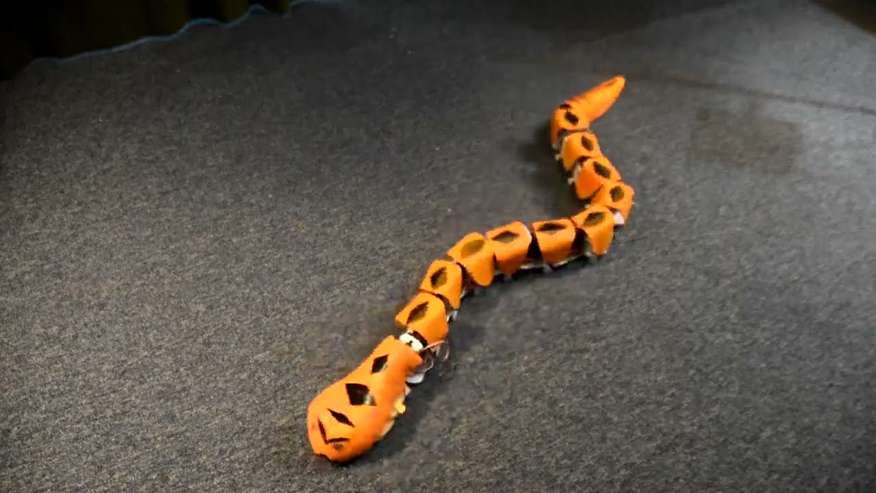
RC Robotic Snake Jan 2025
672
The snake's main construction uses 3D-printed servo holders that are articulated like train carriages, where each link connects to the next. Servos control the horizontal plane articulation of each segment.
Click to watch →

Fuso de Esferas - ENGENHARIA CARGA RÁPIDA - tech!
1.6K
Servo motor selection uses torque-speed curves from manufacturer catalogs. The process involves: (1) determining required torque and speed from application calculations; (2) examining the motor's torque-speed curve showing continuous torque region (blue) and peak torque region (red); (3) verifying the operating point falls within the continuous torque region; (4) ensuring starting torque requirements are met by the peak torque region; (5) considering physical dimensions for installation compatibility. The video demonstrates selecting a servo motor with 1500 RPM and 4.723 Nm torque requirement.
Click to watch →

I Made a Snake Robot #arduino #arduinoproject #robotics
7.4K
A robotic snake can be constructed using multiple servo motors positioned perpendicular to each other, controlled by an Arduino microcontroller with joystick input for directional movement (left/right for forward/backward, up/down for left/right movement), and powered by a PCA9685 servo controller and power supply.
Click to watch →
Deep Dive
Study of biomimetic robotics and gait design, learning how to mathematically model and program snake-like locomotion (e.g., lateral undulation).
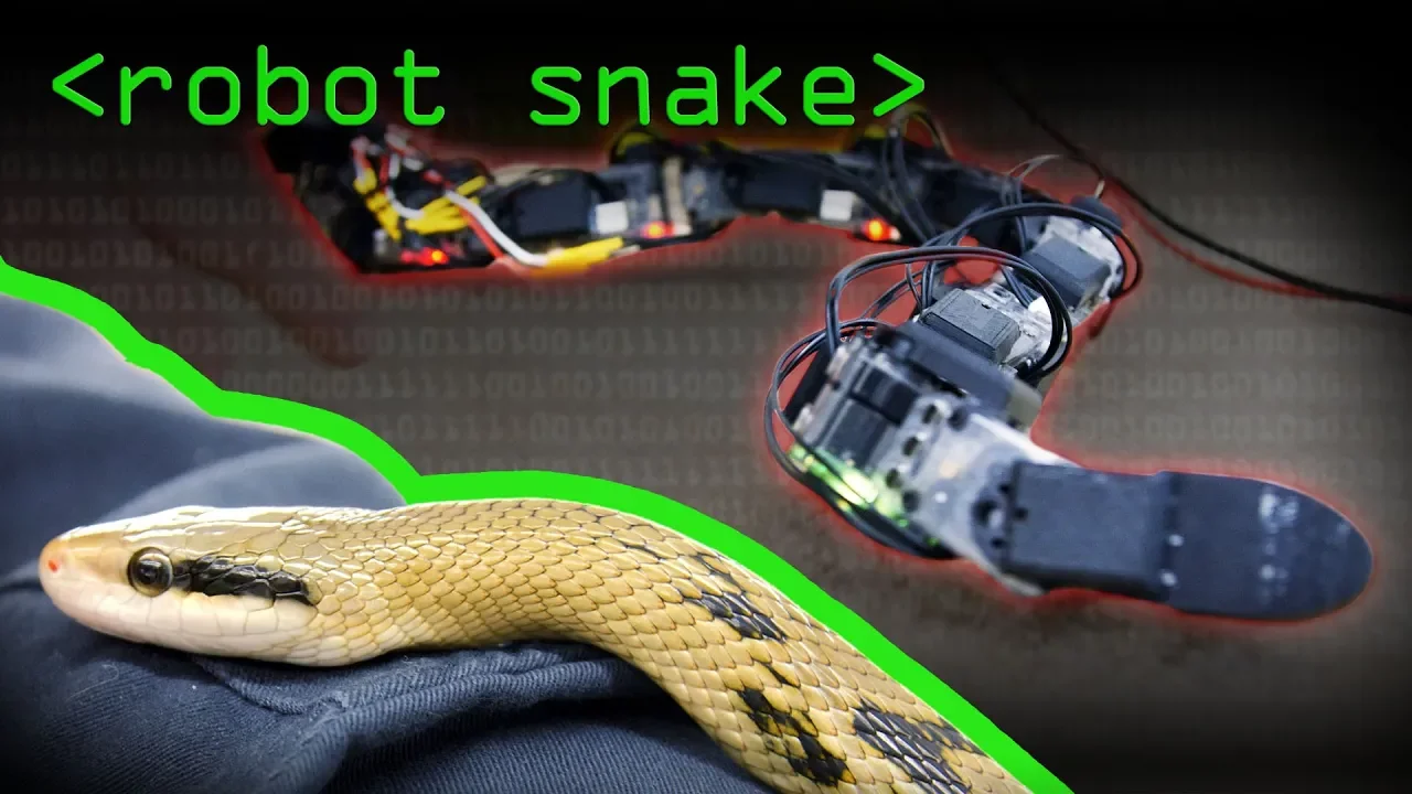
Bio-Inspired Snake Robot Locomotion Explained by Computerphile
118.2K
Snake-like robots can replicate four primary locomotion modes—sidewinding (using two sine waves for desert sand movement), lateral undulation (single wave for typical slithering), concertina (for tunnel navigation), and rectilinear (still under development)—by implementing simple mathematical wave patterns on servo motors, though current robots remain tethered due to high energy consumption and lack sophisticated skin actuators for full biomimicry.
Click to watch →

Secrets of Slithering Snakes | Science Nation
82.7K
Snakes move by pushing their overlapping belly scales into small ground irregularities rather than simply sliding; they lift parts of their bodies to increase speed and efficiency, and they have four distinct movement patterns (undulating, extending/contracting, side-winding, and straight-line motion) that they use automatically from birth, which has inspired engineers to design more versatile snake-like robots for applications like search and rescue and minimally invasive surgery.
Click to watch →

Shake, Shimmy, Wiggle: How Snakes Move!! | Zefrank Reaction
35.4K
Rectilinear locomotion is the most straightforward snake movement, where ribs and vertebrae are pulled along by skin-attached muscles. Belly scales stretch forward, contact the ground, tighten, then pull the skeleton forward. Belly scales have directional friction—smooth forward movement but resistance when pushed backward. Lateral undulation involves curvy movements along fixed paths, with the snake setting anchor points by contracting muscles on one side while relaxing the other. Forces generated during movement cancel out, leaving only forward-directed forces.
Click to watch →
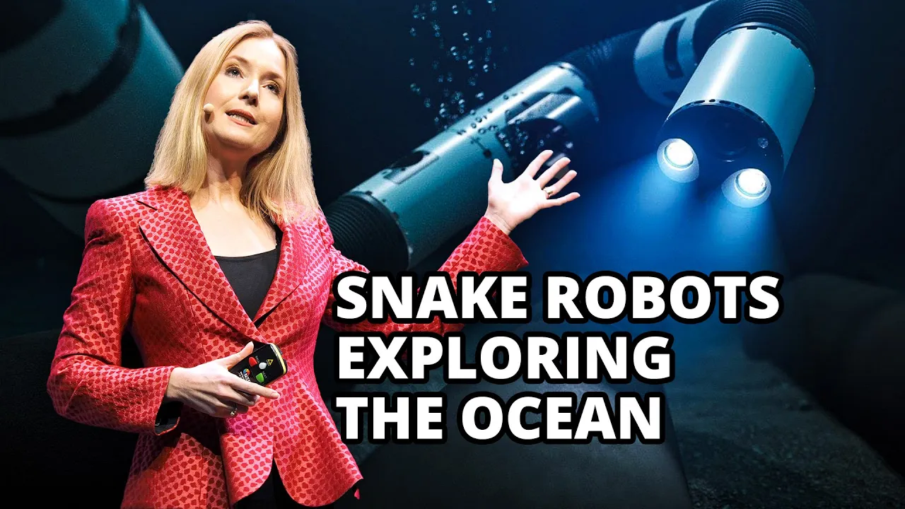
Snake Robots Exploring The Ocean | Kristin Y. Pettersen
7.4K
Sea snakes' long, flexible bodies inspired robotic snake designs. Mathematical modeling became essential because physical prototypes reveal only specific behaviors while models describe all possible snake robots universally. Analysis revealed that undulatory locomotion requires higher sideways friction than lengthwise friction—biological snakes achieve this through scales, while water's hydrodynamic properties naturally provide this for snake-shaped robots.
Click to watch →
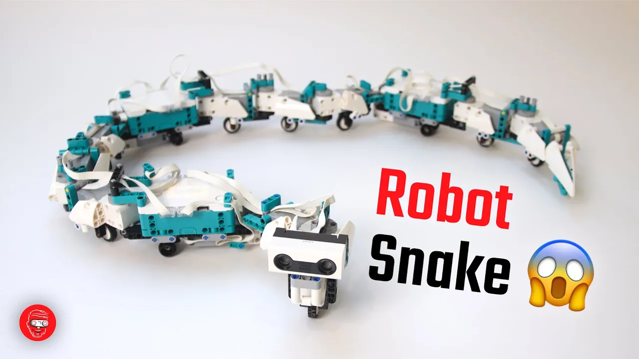
130cm Robot Snake with LEGO MINDSTORMS Robot Inventor: obstacle avoidance and programming
9.8K
This extensive section explains the complete mathematical framework and real-time control algorithms enabling snake-like robot movement. The sine wave serves as the fundamental model where motor angles vary periodically over time. Key parameters include amplitude (movement range in degrees), offset (phase difference between segments), rate (ticks per second controlling wave speed), damping (preventing signal amplification), and curvature (shifting wave center for turning). The first segment has 0-degree offset, the second 45 degrees, creating progressive wave propagation. Motors use error-based power calculation where output depends on the difference between current position and target position. Absolute encoders (0-360 degrees) are converted to relative encoders (-180 to +180) for easier programming. Advanced techniques include amplitude scaling to reduce movement intensity for later segments and prevent cumulative shaking, and motor time offsetting to delay each segment's activation proportionally to its position. The start motor block executes in under 0.01 seconds, enabling rapid calculations for multiple motors simultaneously. This combination of mathematical modeling and real-time control creates smooth, coordinated snake-like movement patterns.
Click to watch →
Deep Dive
Implementation of forward and inverse kinematics to control the exact spatial positioning of the robot's head and body segments.
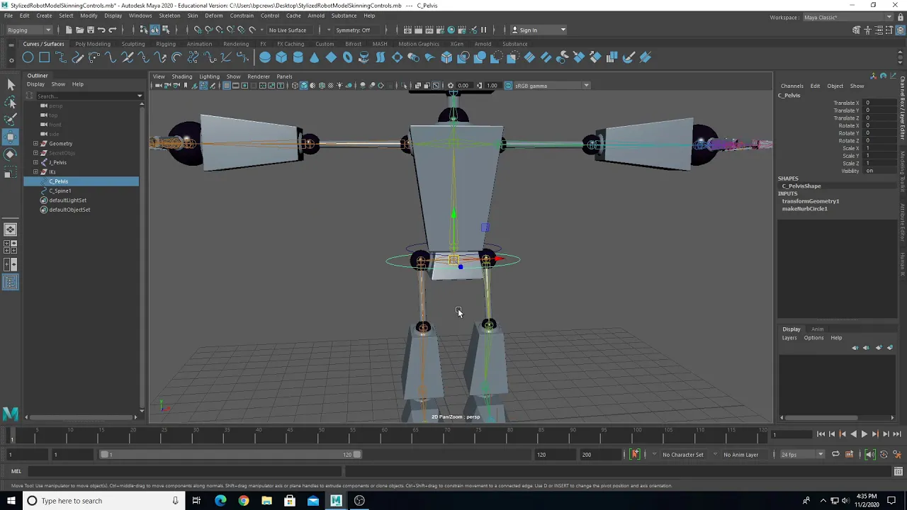
Robot Rigging Part 05 Controls Setup
3.9K
Forward kinematic controls for head and neck are created using orient constraints. The control is snapped to the joint center, frozen transforms are applied, and an orient constraint is created with 'maintain offset' enabled. The controls should be parented in a hierarchy (head to neck, neck to spine) so that when the spine moves, the neck and head move with it. This creates a chain of controls that move together.
Click to watch →

Meet Caroline: Testing ways to build a cheap Robot Arm (for science!)
124.3K
Inverse kinematics (IK) enables a robot arm to move its end effector to specific positions in space while controlling orientation. Unlike forward kinematics which calculates position from joint angles, IK solves for the necessary joint angles to achieve a desired end position. This allows for sophisticated movements like tracked slider moves (keeping focus point fixed while moving head) or tripod-style pan and tilt motions, with complete control over how motion is generated through custom IK solvers.
Click to watch →

인디 모션 캡처 | HQ 라이브 | 인사이드 언리얼
3.4K
This segment demonstrates implementing inverse kinematics for hands and head using the Fabric node. The hosts configure the node by setting the effector transform to world space, specifying tip bones (hands) and root bones (upper arms), and connecting motion controller locations. They show how to set up separate IK chains for left and right hands, explaining that the node calculates bone movements to reach target positions. The segment also covers head IK, using the HMD world rotation to drive the head bone, and addresses the issue of broken wrists that can occur when applying world space data directly to bones without proper conversion.
Click to watch →

MarIOnette Tutorial: Make Your Own Post-It Drawing Robot
13.1K
This section explains two fundamental kinematic approaches for robotic control. Forward Kinematics allows individual bone rotation around specific axes, simulating direct servo control. Inverse Kinematics enables moving an end effector (like a pen) and having the chain automatically adjust to reach it. To implement FK, set rotation mode to XYZ Euler and lock unwanted axes. For IK, add Bone Constraints > Inverse Kinematics, specify targets, set chain lengths, and leave rotation unlocked. Both systems require locking axes appropriately to prevent unintended movement, enabling realistic robotic behavior.
Click to watch →

6 axis robot kinematics Part 1
50.1K
Robot kinematics involves two fundamental calculations: forward and inverse. Forward kinematics determines the tool center point's position (X, Y, Z) and orientation (pitch, roll) in world space based on joint angles. Inverse kinematics solves the reverse problem—calculating required joint angles to reach a specified spatial position. Forward kinematics is computationally straightforward, while inverse kinematics is significantly more challenging due to potential multiple solutions and non-linear relationships between joints.
Click to watch →
Deep Dive
Integration of sensors (such as IMUs or distance sensors) to enable closed-loop feedback control and obstacle avoidance in physical environments.

MathWorks Robot Autonomy and Control Workshop Webinar
1.4K
This section covers obstacle avoidance and control system fundamentals. Obstacle avoidance uses distance sensors to compare readings against thresholds, triggering motor commands to stop before hitting obstacles. This is a closed-loop control system using sensor feedback. The section explains the fundamental difference between open-loop and closed-loop control systems: open-loop has no sensing (commands without feedback), while closed-loop uses sensor information to make decisions. Closed-loop systems are necessary to react to disturbances and environmental changes that open-loop systems cannot handle. The section demonstrates how sensor feedback enables robots to adapt to unexpected conditions like pushing objects or encountering obstacles.
Click to watch →

Complete PhD Defense Process | PhD Defense Questions Highlighted
642
In physical experiments, sensors include a Raspberry Pi camera and IMU (Inertial Measurement Unit). For point navigation tasks, the target has colors (red or green) that the camera detects. A closed-loop controller calculates angles and provides feedback to steer servo motors left or right based on the angle. The camera is not part of the learning loop but only steers the motors, while the learning itself evolves the controller parameters.
Click to watch →

ROBOTICA AVANZADA MODULO II_CLASE 03/VILLA AUTOMATION SAC
106
In closed-loop control systems, sensors are integrated to provide feedback about the system state. The sensor output is compared to the reference signal to generate an error signal, which is then processed by the controller. The controller generates control signals based on this error, which are sent to the actuators. The actuators apply actions to the plant, which produces an output that is measured by the sensors. This closed loop of measurement, comparison, and control allows the system to achieve and maintain desired behavior.
Click to watch →

FTC Beginner OnBot Java Course | Lesson 2 - Initializing Motors
175
This segment explains two fundamental control approaches. Open loop feedback means the robot operates without sensors, running on predetermined schedules without knowing its position. Closed loop feedback uses sensor data (like distance sensors) to make decisions, stopping when detecting obstacles. Closed loop is more accurate but requires sensors. Open loop serves as a fallback mechanism, such as a timer that stops the robot if it runs too long, preventing it from going 'completely haywire' if sensors fail.
Click to watch →

Open and Closed Loop Examples
210K
Sensors provide the feedback necessary for closed loop systems by measuring physical quantities and converting them into signals that can be processed by the controller. Common types of sensors include: limit switches (detect presence/absence), potentiometers (measure position or resistance), photo transistors and photo resistors (detect light intensity), thermistors (measure temperature), IR sensors, ultrasonic sensors, GPS, color sensors, moisture sensors, smoke detectors, carbon monoxide and carbon dioxide sensors, oxygen sensors, chemical sensors, force sensors, pressure sensors, and machine vision systems.
Click to watch →
Design & Parts
Body Assembly
Circuit Plan
Design & Parts
0:00- 1
Presents the 3D-printed snake robot components designed in FreeCAD.
- 2
Explains how the head, body, and tail sections fit together with clips.
- 3
Shows a flexible body structure using linkage joints and printed parts.
Soft Robotics and Continuum Mechanics
An alternative paradigm to rigid, segmented 3D-printed snake robots is soft robotics, which utilizes continuous, elastomeric bodies actuated by pneumatics, hydraulics, or tendon wires. Critics of rigid segmented designs argue that traditional mechanical joints introduce high friction, physical complexity, and susceptibility to environmental hazards like dust, water, and debris, which can easily damage or seize 3D-printed components. In contrast, soft continuum robots offer inherent compliance, continuous deformation, and superior resilience in unstructured environments. By eliminating discrete mechanical hinges, soft snake robots can safely deform around obstacles, squeeze through highly confined spaces, and survive impacts that would fracture rigid plastic linkages. This opposing approach shifts the design challenge from mechanical joint assembly to material science and the complex control algorithms required for non-rigid bodies.
Basic proficiency with parametric CAD software, specifically navigating FreeCAD, sketching, applying constraints, and creating 3D solids.
Understanding of 3D printing design rules (DFAM), particularly design tolerances, clearances for interlocking/moving parts, and material shrinkage.
Fundamentals of rigid body mechanics, including degrees of freedom (DoF), revolute joints, and basic linkage mechanisms.
Familiarity with standard mechanical hardware, such as threaded fasteners, bearings, and pins used to join mechanical components.
Selection and integration of actuators (such as RC servo motors) and electronic controllers to drive the snake's joint segments.
Study of biomimetic robotics and gait design, learning how to mathematically model and program snake-like locomotion (e.g., lateral undulation).
Implementation of forward and inverse kinematics to control the exact spatial positioning of the robot's head and body segments.
Integration of sensors (such as IMUs or distance sensors) to enable closed-loop feedback control and obstacle avoidance in physical environments.
5.5K views109likes5:00@BrainergiserTubeOriginal Release: 2019-01-20
hi guys welcome to the Chinese today I'm back with another governance project [Music] this project is an upgraded version of a previous snake project I made this project long back now you're suggesting before anything and they have some queries and questions among them one is right the cycle is not working so I will definitely explain that and another request was if we modify is a look and feel if I make a 3d structure of me if there is a cover around the body I made to the printed parts this is the body part the best part and the top part would can push fit to each other this I made in freecad this is the base of the head part you can see the two clamps at the top these two terms are used to hold the motors is it a shame that I have designed of this name the page and the head also just pushed and can fit together this is the tail perm altogether when you connect it will look like a snake the two body parts are connected using a linkage so here is the a and base you can see the head has two hams but you can easily fit the mortals [Music] and this is the base part and this is the body part now in this space we are going to feed twins what is in it is SAP and we'll use a safety pin as a SAP it is very easy to get so straight safety page and use two weeks as a wheel and push it into that place now you can see dip in the boys also this is one section of the body on the tail section I have two parts which you have to school together and the three wheels at the back to balance the tail wait now I made almost five body parts and with this group each of the body parts you can connect make sure the screw is not very tight and it is like such a way that the joint is little loose now put the top cover the head and the body so you can see here I have total one two three four five forty parts this is the whole flexible body structure inside this we have to fit the circuit diagram the battery and then it will start working like a snake the block turn of the circuit is there is a basic power supply or a battery which is going risk where it generator is could be one out of less than 1 Hertz the output of the square it will go to an inverter logic inverter and another will come out directly both will go to two electronic switch MOSFET based or relay based now from the both switch it will go to the models in the next part of the video I will explain this circuit and use this you can see this kind of robotic movement has made that movement of the robot just like a sinusoid as away so don't miss the next video if you haven't subscribed my channel please subscribe in that way you will soon come to know but I have posted my next video thanks for watching bye
Up Next
2:00
Sidewinder Robot Mimics Snake Sand Climbing Technique
@ScienceMagazine
94.9K views•2014-10-09

58:25
MathWorks Virtual RoboSub Simulation Environment | Webinar 2026
@RoboNationInc
209 views•2026-03-10

11:04
How to Build a Self-Balancing Robot: Arduino Nano & MPU6050
@easytechzones
16.8K views•2022-03-09

25:22
Micromouse: The Fastest Maze-Solving Robots on Earth
@veritasium
23.5M views•2023-05-24
Related Study Plans & Knowledge Roadmaps
Structured learning paths in Robotics
robotics
Building Delta Robots: Kinematics & Pico
01Foundations of Delta Robots & Mechanical Design
02Electronics and Microcontroller Setup with Pi Pico
03Delta Robot Kinematics and Coordinate Math
+ 3 more learning modules
65h6 modules
Explore Roadmap
robotics
Building Ballbots: Dynamics, Kalman & LQR
01Embedded Electronics & Omniwheel Actuation
02Ballbot Kinematics & Rigid Body Dynamics
03IMU Sensors & Kalman Filter State Estimation
+ 2 more learning modules
42h5 modules
Explore Roadmap
robotics
Micromouse: Hardware, PID Control & Flood-Fill
01Electronics & Teensy Microcontroller Basics
02Sensors and Actuators: Motors, Encoders & IR
03Precision Movement: Implementing PID Control
+ 2 more learning modules
35h5 modules
Explore Roadmap
robotics
CDPR: Kinematics, Arduino & Winch Control
01Foundations of Arduino & Basic Electronics
02Stepper Motors and Winch Mechanics
03Kinematics of 2D Cable-Driven Robots
+ 2 more learning modules
28h5 modules
Explore Roadmap