



![[۹] دورهی آموزشی میکروکنترلر STM32: تایمرها، وقفههای تایمر و سیگنال PWM](https://i.ytimg.com/vi/dMykr0nxWTU/maxresdefault.jpg)






![[Lập trình nhúng] Lúc nào cần học thư viện HAL, lúc nào nên học thanh ghi?](https://i.ytimg.com/vi/6wy-EmWbtIY/maxresdefault.jpg)


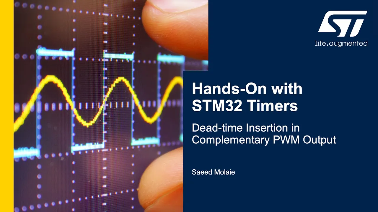










This video explains how STM32 PWM is implemented at different abstraction levels: (1) CubeMX generates code that maps each configuration setting to specific HAL function calls, (2) HAL documentation provides a structured six-step process for PWM setup including timer initialization, clock enabling, pin configuration, and PWM activation, and (3) bare-metal implementation involves directly manipulating hardware registers (TIMx_ARR for frequency and TIMxCCRx for duty cycle) by accessing memory-mapped addresses defined in the HAL library, demonstrating that all abstraction layers ultimately manipulate the same underlying hardware registers.
STM32 Guide #4: HAL vs Bare-Metal PWM Code Explained
Added:Understanding of basic Pulse Width Modulation (PWM) concepts, including duty cycle, frequency, and period.
Familiarity with STM32 architecture, specifically how hardware timers work and their relationship with GPIO pins.
Basic proficiency in C programming, particularly bitwise operations (AND, OR, bit-shifting) used for register manipulation.
Conceptual awareness of the differences between Hardware Abstraction Layers (HAL) and direct register-level (bare-metal) programming.
Implementation of advanced PWM techniques, such as complementary PWM outputs, dead-time insertion, and center-aligned mode.
Integrating Direct Memory Access (DMA) with PWM timers to dynamically update duty cycles without CPU intervention (e.g., for sine wave generation or motor control).
Performance profiling and benchmarking of HAL overhead versus bare-metal execution speed and memory footprint.
Developing a custom, lightweight driver library that bridges the gap between HAL usability and bare-metal efficiency.
110.5K views3.5Klikes26:20Original Release: 2021-03-29
greetings everyone and welcome back i hope you're ready to learn more about stm32 we got some pretty cool stuff today today we're going to spend some time drilling into the code that's generated by cuba max the goal is to understand what it's doing behind the scenes after that i'm going to show you where you can go to find the answers to any questions that you might have when you're trying to learn something new we're going to start with the pwm implementation that we did in the last video and then tear it down all the way to bare metal in case you missed the last video here's a quick recap of what we did in my last video i talked at a very high level about what pwm is i covered buzzwords like duty cycle resolution and frequency and today i want to take a closer look at what we need to do to get our stm32 to do pwm let's start with high level stuff and work our way down to a bare metal implementation we'll kick things off by looking at the code that cubemx generates for us in the last video we used cubemx to set up pwm and this ends up generating code which does all of the magic for us next we're going to look at the hardware abstraction layer and see how we can control pwm with that we saw one example of how being used in the last video when we used it to start the timer and finally we're going to tear down that hell implementation to see what registers are actually being changed behind the scenes spoiler alert this is one of the registers we're going to look at let's take a second to review some of the most important stuff that we covered in the last video the duty cycle is a percentage and it means how long the signal is high compared to low over here we have a video of pwm with an increasing duty cycle next up is resolution this is essentially how many clock ticks make up one pwm cycle in the video over here you can see that the blue signal has a worse resolution so it seems to be a little bit choppier but the yellow signal looks nice and smooth and this is because the blue signal has a lower resolution than the yellow signal lastly we have frequency the pwm frequency is how many cycles we have per second in this video we can see that the blue signal repeats four times as often as the yellow this means that blue has a higher frequency than yellow let's start with the highest level cube mx these are the settings for a timer that we saw in the last video the only two settings for this timer that we changed were counter period and auto reload preload actually i need to interrupt myself here mark day pointed out to me in the comments that auto reload preload does something different than i've been explaining with that being said i've already recorded a lot of this video so i'm just going to leave it in for now just know that enabling or disabling this parameter won't affect your pwm signal at all and if you're curious what this actually does i'll explain it at the very end of the video the counter period just tells our timer what number to count up to i chose 255 but you could choose whatever you want this just means that we're going to count from 0 to 255 start over and repeat that process indefinitely since the timer is set up and running we're able to work with the pwm channel the pulse value affects the duty cycle and i set mine to 25.
this just means that our output's going to be high from 0 to 24 and then drop low until we hit that maximum value of 255 if you do the math this comes out to roughly 10 duty cycle now all of this configuration that we did in cube mx ends up generating code which you can see here auto-generated code like this was one of the reasons that stm32 seemed so overwhelming for me to learn for the first time now i don't just want to say hey don't look at this code it's auto-generated you don't need to worry about it while that is kind of true i find it pretty comforting to understand what's actually happening so let's see if we can make some sense of this code right now there's a lot of stuff here so let's see if we can simplify it a little bit i highlighted a little chunk of code here and let's see what's actually happening this is what this little chunk of code looks like the meat of the code is really this hal call where we're actually initializing the pwm but everything outside of that red rectangle is really just for error handling you typically don't want to remove error handling but in this case it makes our code a lot cleaner and easier to read so let's just strip out the code that actually checks to see if init returned okay this condenses this chunk into a single line of code and it's pretty easy to understand what it's doing now so let's take a look at the full generated code again we can see that they do this trick about six times so let's condense these into one liners before and after we still have a little ways to go next i'm going to remove these comments now once again i'm only doing this to make our code more readable these comments actually perform a pretty important role when it comes to generating code so you don't want to get rid of them normally after removing those comments this is what we're left with at this point the text is big enough to read now i'm going to organize these into smaller bite-sized chunks of code the goal of reverse engineering this code is not to understand every little detail that's happening it's more just to give us a level of comfort to understand what cubemx is doing behind the scenes so i'm just going to look at this from a very high level and not focus on all of the nitty gritty details let's run through this one chunk at a time this first chunk just declares some complex variables that we're going to use later in the code here's the three variables and i color coded them as red green and blue and these end up getting used later on what they're actually doing will make sense in just a little bit so for now let's look at the next chunk the meat of this chunk of code is really just this very last line of code and this only takes one argument which is htim2 all of the lines before this are really just configuring that variable maybe you're asking yourself why does it look like this let's look at an alternative to do the base initialization of this timer we need these six arguments so one way to handle this would be to create a function that just takes in six arguments however st decided to tackle this problem a little differently so instead they create these complex variables or type definitions here's an example of one called tim underscore handle type def and this is really just a collection of all of the parameters that are needed to set up that base timer so we create a variable called htm2 and set it equal to this complex variable type so now when we're ready to call hal tim base init we just have to pass in that one variable all of these settings live within this htm2 variable and also this ampersand is c syntax for pass by reference that has to do with things called pointers in c programming and i'm not going to cover that in this video so if we revisit this code we can see that the first couple of lines of code are actually just setting all of the settings and then this last line is where we pass in that complex object and actually initialize the base timer let's put this chunk of code side by side with the cube mx configuration tool is this starting to make sense yet every parameter that we set in cubemx ends up generating a line of code so cubemx is actually pretty cool it gives us a graphical way to see all of the parameters instead of memorizing a bunch of code and maybe forgetting a line or two okay let's move on to the next chunk here we see the same pattern we have some complex variable which i forgot to tell you is called a struct we set the parameter of the configuration variable which in this case is the clock source and then we pass that configuration variable into this hell call which then actually sets the clock source if you're curious this is the drop down menu in cube mx which affects this variable this was part of the setup for timer two the next chunk of code is just a hail call it doesn't have any configurations to set up up next we have this master config and this works the same as everything else we set the parameters of the master config variable here and then pass that variable into the actual hell call which then sets the master config synchronization once again this chunk of code pulls its variables from this part of cubemx and once again we have a same chunk of code here which sets the s config oc part and this affects channel 1 of our timer here you can see where we're setting our pulse value of 25 and these variables are set from this part of cube mx this next part is a mistake on my end i was playing around with channel 4 and i forgot to undo my changes before taking this screenshot however it is pretty cool to see that this is the only code that gets added to add another channel to your timer you might even notice that it's using the same s config oc variable that we used to set up channel 1.
that means that it has all the same settings as channel 1 and the only thing that's different is it has a pulse value of 0 instead of 25 and then this last chunk of code is called msp post init i haven't actually looked at this before but it looks like it's code that's intentionally set to run post initialization or after the initialization i have no fear because as part of this video we're going to look at some hal documentation and we'll be able to figure out what this actually does and that's pretty much it i hope this gave you some insight as to what's happening behind the scenes when cube mx is just generating all of this magic code it's almost like every setting in cube mx generates one line of code so when you put the two side by side it's actually pretty easy to understand it's also pretty cool to just look at the hal calls that are generated essentially these are the five commands that are used to set up pwm for now let's just jot these down and we'll revisit them in a bit now we've looked at the code that cubemx generates so let's move one level lower and take a look at how hal is used to set up pwm everything that you need to know about hal can be found in the hal documentation the documentation for hal is slightly different between different families of microcontrollers and since we're using the blue pill which is the stm32f103c8t6 we want to search for the f1 hell documentation the documentation between different families of microcontrollers is very similar so there's a lot of overlap between the different hell documentations and this is what the hell documentation looks like a modest 1 208 pages of technical documentation if you want to read the whole thing no one's going to stop you but i like to use the table of contents i'm looking for some pwm stuff and i think that falls within the timer documentation so if i scroll down here i can eventually get to the section i'm looking for when looking through the table of contents you can expand or collapse these menus to see more most chapters tend to be broken up into these three parts the first section talks about structures or the structs that we saw earlier here's an example of the stuff that you would see within this section and this looks very similar to the example i gave earlier when we were breaking down the cube mx generated code the next section is the api description which is human readable instructions as well as function definitions in this section you can find things like how to use this driver which tells you exactly what you need to do to get this to work this section is a goldmine when you're trying to learn something new the last section is a collection of defines this is really just a giant list of all the defined statements these are used when setting up the structs or maybe calling functions let's try to figure out how to use pwm by just reading the hell documentation my favorite place to start is the section called how to use this driver it gives us a step-by-step explanation of what we need to do to set everything up for timers and pwm there's six steps so let's walk through these one at a time and keep a running list of all of the functions that we need to call to get this working let's start with step one this is telling us to initialize the timer's low level resources we have a list of functions below and we're going to use whatever one seems to be the most relevant to pwm and they have a bullet point specifically for pwm so that means that we need to use this hal tim pwm msp init we're going to add this function to our running list of things that we need step two step two looks like it's more low level resources part a tells us to enable the timer interface clock with this function so we'll go ahead and add that to our list part b tells us how to set up the timer pins using this function and the next bullet point tells us to set these up in alternate function mode using hell gpio init so we'll add this to the list as well step three step three tells us how to use an external clock if needed we're just going to be using the internal clock so that means that we can skip this step step four step four is telling us to configure the timer in the desired functioning mode and we're going to do this by using some of the initialization functions listed below up first we have hal tim bass init which says that it generates a simple time base so let's go ahead and add that to our list the next bullet point that seems applicable to us is the stuff that talks about pwm and they list hal tim pwm init and hal tim pwm config channel and it specifically tells us that these are used to generate a pwm signal so let's add these to our list step five now it's time to activate the timer peripheral so we're going to use one of the following start functions depending on what we're doing since we're using pwm we want to use one of the pwm start functions in this case they list three different things that we can pick from we've got just a normal start we have start with dma and start with interrupt direct memory access and interrupts are more advanced ways to use pwm but we're just going to stick to a normal start so let's add this start function to our list and finally step six step six describes something called dma burst and as i just said we're not using direct memory access so we can skip this step and that was the last step so now we have a list of all of the functions that we need to call to get pwm set up let's compare this side by side with the functions that were generated by cuba mx you can see that they're not identical but there is some overlap what we have highlighted here are things that showed up in the hell documentation but not in the cube mx generated code and over here we have things that were generated by cuba mx but didn't show up in the hell documentation let's see if we can figure out why let's start with an easy one the hell documentation told us to use this pwm start function and this was something that even with the cube mx generated code we had to add manually in our main method so even though it wasn't automatically generated it was still required to start the timer so that just leaves us with these four missing functions why did they show up in the hell documentation but not the generated code we'll come back to this in just a second let's take a look at these two functions that were generated by cuba mx but didn't show up in our hal instructions we'll start with this master config synchronization i searched the hal documentation and found this little excerpt of the function the function description tells us that this configures the timer in master mode that was one of the advanced parameters in cuba mx that we didn't mess with this means that unless we're trying to set up our timer in master mode we don't actually need this function call up next i wanted to look for msp post in it and this is one of the things that i said i didn't actually know what it did and it turns out it doesn't even show up in the hell documentation so to find out what this function was doing i held the control button and clicked on the function which jumps me to the implementation this is what the code looks like for msp post in it after looking at this for a bit two things stood out to me these two functions here clock enable and gpio init are two of those missing functions that we looked at earlier so that means that they weren't missing after all and they were just buried within a different function so of course i had to know do these two other functions actually show up in the generated code just buried a little bit deeper i performed a search across all of the files in this project for these two missing functions and then i hunted through the results to see where it was actually being called sure enough after a quick search i ended up finding both of them the hal tim pwm msp init function is actually called from within the hal tim pwm init function and the hal rcc timer clock enable is buried just one layer lower hal tim basin it calls hal tim bass msp init which then calls our function down here now something interesting is that the parent functions actually already showed up in our list that just means that by calling these functions we're indirectly calling the underlying functions as well so now why did we spend so much time looking at this well the moral of the story is that the generated code is doing the same thing that's described in the hell documentation they just organize it a little differently so at this point hopefully you feel more comfortable about where this code is generated from and if you don't like the code that cuba mx generates now you know how to do it yourself by just reading the hell documentation so now let's use the hal documentation to do something new let's figure out how to change the duty cycle using hal if you recall from earlier the duty cycle is controlled by this pulse value here so we need to figure out how to change the pulse value using hal we can do that using a function called hal tim set compare i do have to admit something that's been bothering me for a little while i do know that the hal tim set compare function is what we're looking for but just by reading the hell documentation nothing really points you in that direction the hell documentation doesn't really say if you want to change the duty cycle use this function so i'm not exactly sure how you would find this if you didn't already know what you were looking for this is called out in the microcontroller's datasheet it just doesn't show up in the hell documentation so anyway let's jump in and figure out how to use this the description is pretty helpful it tells us that we can set the timers capture compare register which is the pulse on runtime without having to call config channel again we'll fill in everything that we need to know about this function down here the first parameter that we need is the handle this is really a reference to one of those complex timer objects since we're using timer 2 we need to pass in a reference to timer 2's handle we can pass this variable by reference by using ampersand and then htm 2. the next parameter that we need to specify is the channel since we're specifically using timer 2 channel 1 to generate our pwm output we need to use channel 1. so we'll pass in tim channel 1 as the second argument the third and final argument is the compare value this tells us that this value specifies the capture compare register's new value this is our pulse value so this function down here is what we need to implement and code to change our duty cycle let's implement this inside of our infinite while loop to change our duty cycle on the fly to start i'm going to go to the user code section and create a variable that will keep track of our pulse we'll start with a pulse of 0 and we'll count all the way up to 255 and then we'll tell it to start over now inside of our while loop we'll just increase this pulse value by typing in pulse equals pulse plus one next we want this to restart after we hit 255 so i'm just going to say if pulse is greater than 255 we're going to set it back to zero to all of you advanced programmers out there yes there's much cleaner ways to write this but i'm going to stick with this for simplicity so now we're going to use that hell call to change the duty cycle so we're going to do that by typing in underscore underscore hal tim control space here and i think that was set compare yep there it is and now we can pass in the three required arguments the first is the reference to html2 the second is the tim underscore channel and i'm going to use ctrl space here to get tim channel 1 and then our actual pulse value is just going to be that variable that we created now if we leave everything like this it's going to be increasing our duty cycle really fast so we're going to want to add some sort of a delay so we can watch it happen and we're going to do that by using hal underscore delay and we'll wait 100 milliseconds actually i'm changing my mind we'll wait 10 milliseconds okay you know the drill before we can push our code we need to set the boot jumper to program mode and press the reset button okay let's push the code and see what happens all set let's check it out now we need to set the blue pill back into run mode by changing the jumper and pressing reset one more time now i'm going to hook up my oscilloscope we'll start by hooking up the ground pin and then we'll probe pin pa0 which is timer 2 channel 1.
hey look it's working we can see that our duty cycle is increasing from 0 up to a hundred percent or our pulse from zero up to 255 and then it starts over now we figured out how to use hal but it's time to go one step further bare metal now when i say bare metal i mean that we're going to be controlling the microcontroller by manipulating the registers directly we're literally shoving numbers into certain places of memory which is causing the microcontroller to do things if you're programming at this low of a level it often means that you need to do a lot of reading and your code probably isn't going to make sense to anyone else unless they've also done a lot of reading it's often significantly more complex to implement things at the bare metal level so for the sake of simplicity in this video the only thing that we're going to change at the register level is going to be our pulse or duty cycle to learn how we looked at the hell documentation but now we want to look at the documentation for the microcontroller itself what we're specifically looking for is called the reference manual although i do tend to slip up and call this a data sheet every once in a while the data sheet is more like the electrical characteristics while the reference manual is more of the programming guides so we want the reference manual for whatever microcontroller we're using and once again we have a nice 1136 pages of technical documentation this document also has a table of contents just like the hal documentation but they also actually list it in the first couple of pages down here what we want to find is all of the documentation for timers and pwm we can see that timer documentation starts at chapter 14 and there's actually different rules depending on which timers we're using so here's example for timer 1 and 8 and on the next page we have examples for timer 2 to timer 5. for the blue pill there's four timer sections we have one for advanced control timers two for general purpose timers and one for basic timers we're generating pwm using timer two so we want to refer to chapter 15 which describes general purpose timers which includes timer two and if we keep looking through the table of contents for this chapter eventually we can find a section on pwm mode which is 15.3.9 so here's what section 15.3.9 looks like and right away in the first sentence it tells us pretty much exactly what we're looking for it tells us that pwm mode allows us to generate a signal with a frequency determined by the tim x arr register and a duty cycle determined by the value of the tim x ccrx register so once again we're trying to change the duty cycle so the duty cycle is determined by the tim x ccrx register so this is the register that we're looking for so by changing this register we change the duty cycle it's cool that we found out what the register is but how do we change it we could either use ctrl f to search the datasheet for it or we can go into the table of contents and find the description of all of the registers the table of contents lists a ton of registers and we can actually see the ccr registers that we're looking for the description before called it ccrx but here we can see that there's ccr 1 2 3 and 4.
so calling it ccrx is kind of just shorthand for any one of these now since we're using timer 2 channel 1 to generate our pwm signal we want to look at the documentation for channel 1 which is ccr1 this section describes in detail what this ccr1 register is and if you want to learn how to set this register directly by its memory address i'd encourage you to go look at my series called bare metal micro controllers but for this video let's just make a mental note of this address offset which is 3 4 and hex now thankfully we don't actually have to calculate that memory address ourself part of the hal is actually defining all of the registers and pointing them to their respective memory addresses pretty much any hardware abstraction layer that you're using even if it's not the one by st is going to have a list of all of the registers and where they point to in memory so in here we can actually see where ccr1 2 3 and 4 are defined and right here they actually have a comment telling us that it's pointing to an address offset of 3 4 in hex which is exactly the same as what they list in the datasheet so now we want to change the duty cycle by manipulating the register directly instead of using this hal call so i'm just going to highlight this and delete it in its place we need to change timer 2's ccr1 register and the way that we can access that register without having to find the memory address manually is typing in tim2 and then typing dot you'll see that this auto corrects to an arrow because technically tim2 is a pointer and in order to dereference a pointer you need to have the arrow instead of a dot it's kind of cool that the ide does this for you anyway now we see a list of all of the registers that are inside of timer two and right here we can see ccr1 so now we can set the value of ccr1 by just typing in equals and pulse now we want to test this out and to make sure that we actually did something we want our oscilloscope to look a little different so i'm just going to change the delay on this from 10 milliseconds to one so it should go really fast let's push the code and there we have it we're changing the duty cycle directly from the register we can tell that we actually did something because now this is going a lot faster than before as we continue to learn new things there's always going to be a trade-off between using cuba mx hal or bare metal implementations so hopefully after watching this video you understand the strengths and weaknesses of all three of these things and even if you don't like working at such a low level at least now you should have some level of comfort understanding what's happening behind the scenes of generated code additionally this applies to more than just stm32s pretty much all microcontrollers have a very similar stack up i was invited to give a presentation at the embedded online conference 2021 so my next video is actually going to be focused on this the actual conference starts on may 17th so it might be a little while before you see my next video uploaded as soon as i finish that video i'll start part 5 of this series that's all for now see you next time as i mentioned earlier i made a mistake in my last video when talking about the auto reload preload i said you needed to enable it to cause the timer to restart over and over again but it turns out that that is not true at all you can completely ignore this but i did want to say what it actually does something we saw earlier when looking at the pwm mode documentation is that we see the frequency is determined by the arr register that's the auto reload register this is the number that our timer counts up to before starting over at zero if this is the auto reload register what is the auto reload preload if we do look at the documentation for the arr register we see this little note here telling us to refer to section 15.3.1 for more details about the arr register and update behavior when we jump to this section it tells us that the auto reload register is pre-loaded so writing to or reading from the auto reload register is actually accessing the preload register and then the contents of whatever we write to that preload registered are transferred to the shadow register spooky the reference manual even gives us two timing diagrams to show what happens when auto reload preload is disabled and what happens when it's enabled here you can see the shadow register kind of lagging behind the preload register so overall this is totally not important unless we're reading to or writing from the auto reload register a lot
Up Next
13:48
STM32 HAL I2C Tutorial: Interfacing MPU6050 IMU Sensor
@steppeschool3629
36.7K views•2022-05-02

30:32
Ultrasonic Transducers: Resonant Frequency Measurement and Horn Design
@imajeenyus42
229.9K views•2017-02-22

54:16
Polymer Environmental Degradation: Mechanisms & Stabilization
@iit
1.8K views•2012-07-10

33:39
How a Student's Question Saved a NYC Skyscraper from Collapse
@veritasium
22.8M views•2025-04-26
Related Study Plans & Knowledge Roadmaps
Structured learning paths in Engineering
engineering
Building Acoustic Levitators: Physics & Arduino
01The Physics of Sound and Standing Waves
02Piezoelectric Transducers and H-Bridge Drivers
03Arduino Programming: Generating 40 kHz Signals
+ 2 more learning modules
14h5 modules
Explore Roadmap
engineering
Building Peltier Cloud Chambers: Particle Tracks
01Cosmic Rays & Cloud Chamber Physics
02Thermoelectric Cooling (TEC) Fundamentals
03Custom Liquid-Cooling Loop Design
+ 2 more learning modules
18h5 modules
Explore Roadmap
engineering
Yagi-Uda Antennas: Modeling, Build & VNA Test
01Introduction to RF and Antenna Fundamentals
02Yagi-Uda Antenna Design Principles
03Antenna Modeling and Simulation in 4NEC2
+ 2 more learning modules
18h5 modules
Explore Roadmap
engineering
ECG Monitor Design: Op-Amps, Filters & Noise
01Electronics & Breadboard Basics
02Op-Amps and Instrumentation Amplifiers
03Bioelectricity and ECG Fundamentals
+ 2 more learning modules
18h5 modules
Explore Roadmap