























Cable stayed bridges are efficient bridge structures that use one or more towers with cables running directly from the tower to the deck, transferring loads as axial forces rather than bending moments; unlike suspension bridges which require expensive end anchorages, they are self-anchored and can be constructed faster, though they are less favorable for very long spans due to compression introduced by the stay cable system; the cables can be arranged in pure fan, harp, or modified fan configurations, each offering different structural efficiency, aesthetic appeal, and construction advantages depending on the specific bridge requirements.
Cable-Stayed Bridges: How They Work and Their Design
Added:Fundamental concepts of structural forces, specifically tension, compression, and shear.
Basic vector mechanics, specifically how diagonal forces resolve into vertical and horizontal components.
An introductory understanding of basic bridge typologies, such as beam, arch, and truss bridges.
The role of primary bridge components, including the deck, towers (pylons), and foundations.
Advanced structural dynamics, including aerodynamic stability, wind flutter, and seismic resistance in cable-supported spans.
The balanced cantilever construction method and the precise process of cable tensioning and tuning.
The design and mechanics of extradosed bridges, which hybridize elements of cable-stayed and prestressed girder bridges.
Material science innovations in bridge building, such as the use of ultra-high-performance concrete (UHPC) and carbon-fiber-reinforced polymers (CFRP) for stays.
46K views462likes10:12Original Release: 2022-11-24
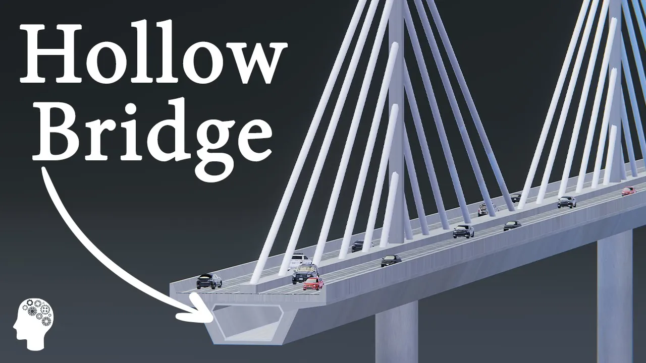
A cable-stayed bridge has one or more towers, from which cables support the bridge deck.
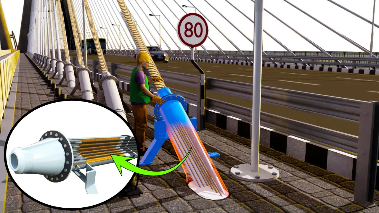
A distinctive feature are the cables or stays, which run directly from the tower to the deck, normally forming a fan-like pattern or a series of parallel lines.
The use of cables as the primary load carrying elements in bridge structures has proven very efficient due to high strength-to-weight ratio of the cable material, will decrease the escalation of the dead load otherwise related to longer spans.
Cable-stayed bridges have become very popular since completion of the first modern cable-stayed bridge, the Stromsund Bridge in Sweden, in 1955.
Due to the versatile nature of cable-stayed bridges, this type of bridge design is adopted for a variety of span lengths, from footbridges less than 50 meters in length, up to spans of more than 1000 meters carrying traffic load.
There are currently well over 1000 cable-stayed bridges around the world.
Welcome to Engineering Concepts, today we will discuss about Cable stayed Bridges.
How Cable stayed bridges work The basic structural form of a cable-stayed bridge consists of a number of triangles composed of the pylon, the stiffening girder as deck of bridge, and the stay cables holding the deck.
Bridges mainly carry vertical loads, a bridge transfers the dead load or self-weight and vehicular loads from deck to girders, and then to foundation through abutments.
In cable stayed bridges, these loads are transferred locally by the stiffening girder to the elastic supports provided by the stay cables and subsequently through tension in the cables to the pylons.
Compressive axial forces in the stiffening girder and in the pylons are in equilibrium with tensile forces in the cables.
Hence the loads are mainly transferred as axial forces rather than bending, which generally results in a more efficient and economical structure.
The dead load of the stiffening girder induces pre-tensioning of the stay cables that increases the stiffness of the structural system.
How Cable stayed bridges are Different from suspension bridges The foundations of an earth-anchored structure like a typical suspension bridge have excessive cost.
Cable-stayed bridges are usually self-anchored structures and unlike suspension bridges, they do not require any end anchorages for cables.
Therefore, cable stayed bridges offer a good solution at locations where the soil conditions are not good for end anchorages.
As a consequence of the self-anchored system, a cable-stayed bridge is typically faster to construct in comparison with a suspension bridge.
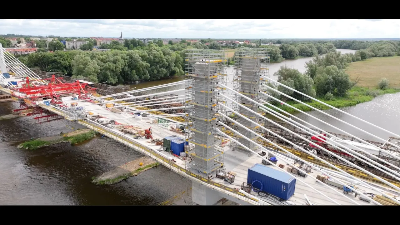
Because erection of the superstructure can start as soon as the pylons reach the height of the first cable anchor points.
However, the arrangement of the stay cables in combination with the self-anchored system introduces compression in the girder which makes cable stayed bridges less favorable for very long spans.
Whereas, suspension bridges dominate with the evolution in design and materials adopted for record span cable-stayed bridges and ultimately the development in achievable span length.
Cable stayed bridges offer diversity Record long spans obviously require efficient structural systems.
However, it is also worth mentioning some of the large number of cable-stayed bridges with more moderate span length, but very spectacular designs that have been completed.
These structures fully demonstrate the diversity in terms of span arrangement, pylon shape, cable configuration and girder arrangement offered by this bridge type.
One of the most famous examples is probably the Alamillo Bridge in Seville, Spain.
Completed in 1991, the bridge features a single inclined pylon, leaning backwards away from the main span and arranged without backstays.
The balance for permanent loads is achieved by a combination of a lightweight steel girder and a heavy concrete pylon.
Live loads result in global bending in the girder and pylon.
Due to the arrangement construction was relatively complicated and the structural system is obviously not very efficient.
The main span length is 200 meters Configuration of cable stayed bridges Depending on the obstacle to be crossed and site conditions, cable-stayed bridges are usually arranged as two-span, three-span or multi-span bridges.
The two-span arrangement consists of a main span and a shorter side span (also referred to as back span).
The three-span arrangement, which is the most common, consists of a main span and two side spans, where the length of each side span equals half of the main span length or less.
Similarly, a multi-span cable-stayed bridge has a number of main spans and a side span at either end.
Vertical restraints are arranged towards the ends of the cable supported portion of the bridge.
The vertical restraint is usually located at the abutment or, in case of a longer crossing with approach viaducts, over one or a number of side span piers.
Anchor cables attached over the vertical fix point provide an efficient horizontal restraint of the pylon top.
Purpose and Arrangement of Cable stays The purpose of the stay system is to assist the stiffening girder transferring the loads from the girder to the supports of the structure.
The loads to consider when choosing the arrangement of the cable planes are vertical and lateral forces and torsional moment.
Typically, the vertical loads originating from dead load and traffic load are dominating.
Furthermore, eccentric live load will result in rotation (twist) about the longitudinal bridge axis.
For very long spans or very narrow bridges, where the width-to-span ratio is small, horizontal load like wind load and the dynamic effects of wind may become dominant.
General arrangements of stay cables Looking at the bridge in elevation the stay cables are usually arranged according to one of the basic systems Pure fan system, harp system and modified fan system, which is sometimes also referred to as semi-fan or modified harp system.
As a general rule of thumb, the longest cables should not be arranged with an angle with horizontal less than 21 degrees to 23 degrees, in order to be effective in transferring vertical loads.
This means that the ratio of the pylon height above the bridge deck to the main span length is typically in the order of 1 ratio 5.
If cables are flatter than this they rather act as external prestress and the bridge type is commonly referred to as extradosed In the fan system all stay cables are radiating from an anchorage point at the pylon top.
Due to space limitations and practical detailing the pure fan system is mainly found in bridges with only few sets of stay cables.
As the trend moved towards multi-cable systems with many relatively small stay cables.
It was found more favorable to spread the anchorage zone out in the upper part of the pylon leading to the modified fan system.
With the harp system the stay cables are parallel and the anchorages are spread over practically the entire height of the pylon above the stiffening girder.
Structural Point of View From a structural point of view, the fan and modified fan system offer a more efficient cable system but relays on bending stiffness of girder and pylon.
But if an anchor cable is arranged, connecting the pylon top to a point of vertical fixity over a side span pier, the system becomes more stable even if the bending stiffness of the girder and pylon is ignored.
In a harp system only the stay pairs including an anchor cable can transfer vertical loads without relying on the bending stiffness of girder and pylon.
Furthermore, the inclination of the stay cables is more favorable with the fan and modified fan system.
As the flat angle is only necessary for the longest cables whereas the shorter cables are more vertical and thus more efficient in transferring vertical loads.
In a harp system all stay cables are parallel and have the same flat angle resulting in a higher compressive normal force accumulating in the stiffening girder towards the pylon.
Aesthetic Perspective However, from an aesthetic perspective it can be argued that the harp system has an advantage because the array of parallel cables will always appear parallel irrespective of the viewing angle.
Fan and modified fan systems with two cable planes tend to appear more disorganized and due to the variety of angles the cables appear to cross when the bridge is viewed under an angle.
This is to some degree mitigated when a multi-cable system and stay cables of a light color are adopted, but the effect is still there.
From Construction point of view From a construction and programming point of view the harp system allows girder and stay cable installation to start earlier before the pylon reaches full height, because the cable anchorages in the pylon begin at a lower elevation.
Architectural Lightening Cable-stayed bridges are often landmark structures and it has become popular to provide these with architectural lighting to highlight special architectural features.
Consequently, it may be quite a different experience to cross a bridge or view it from a distance at daytime and at night, respectively.
Up Next
40:56
Beipanjiang Bridge Construction: Engineering the World's Highest Cable-Stayed Bridge (565m) Explained
@BlueprintITVS
776.3K views•2025-09-24

30:32
Ultrasonic Transducers: Resonant Frequency Measurement and Horn Design
@imajeenyus42
229.9K views•2017-02-22

54:16
Polymer Environmental Degradation: Mechanisms & Stabilization
@iit
1.8K views•2012-07-10

33:39
How a Student's Question Saved a NYC Skyscraper from Collapse
@veritasium
22.8M views•2025-04-26
Related Study Plans & Knowledge Roadmaps
Structured learning paths in Engineering
engineering
Building Acoustic Levitators: Physics & Arduino
01The Physics of Sound and Standing Waves
02Piezoelectric Transducers and H-Bridge Drivers
03Arduino Programming: Generating 40 kHz Signals
+ 2 more learning modules
14h5 modules
Explore Roadmap
engineering
Building Peltier Cloud Chambers: Particle Tracks
01Cosmic Rays & Cloud Chamber Physics
02Thermoelectric Cooling (TEC) Fundamentals
03Custom Liquid-Cooling Loop Design
+ 2 more learning modules
18h5 modules
Explore Roadmap
engineering
Yagi-Uda Antennas: Modeling, Build & VNA Test
01Introduction to RF and Antenna Fundamentals
02Yagi-Uda Antenna Design Principles
03Antenna Modeling and Simulation in 4NEC2
+ 2 more learning modules
18h5 modules
Explore Roadmap
engineering
ECG Monitor Design: Op-Amps, Filters & Noise
01Electronics & Breadboard Basics
02Op-Amps and Instrumentation Amplifiers
03Bioelectricity and ECG Fundamentals
+ 2 more learning modules
18h5 modules
Explore Roadmap