












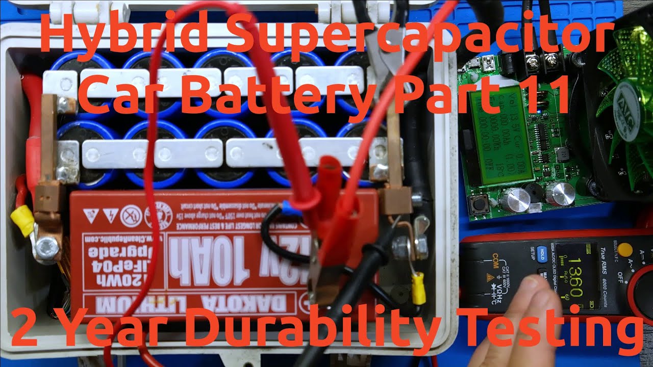









This video demonstrates how to construct a super capacitor bank using six Maxwell BCAP0010 capacitors (2600F, 2.5V) rated for automotive applications. The key technical challenge addressed is voltage balancing in series-connected capacitors, where some cells charge faster than others and risk overvoltage damage. A dedicated balance board monitors each cell's voltage and uses semiconductor switches with heatsinks to bleed off excess voltage, protecting the capacitors. The build requires heavy-duty 2-gauge copper wiring with proper soldering techniques using a 100W iron, and the finished bank can be charged using a lab power supply with constant current control (12-14V DC). The system can function as a vehicle jump starter, though charging takes approximately 12 minutes due to the capacitors' low internal resistance.
DIY Supercapacitor Bank: Construction & Assembly Guide
Added:In this video, I'm going to show you how you can build your own super capacitor bank, which might be able to replace the battery in your car.
So, before we get into going over the components we're going to need for this build, I do just want to quickly mention that this video is going to be dedicated on the construction side of things rather than demonstrating what it is and how it works and how effective it is.
So, if you want to see how the super capacitor battery bank works, click the video link up here. It'll take you to a video demonstrating some of its uses and how good or bad it performs in real world tasks. So now let's have a look at the components we're going to need. So there will be as usual detailed specifications of all the components I'm using here down the video's description.
So do check that out. Um so now let's start off with our capacitors. Now these are made by Maxwell and they are rated for 2 1/2 volts and their capacitance is 2600 farads. And yes, that's not a typo.
2600 farads. These are some pretty hefty capacitors and we're going to need six of them. So, what else have we got?
Well, we've got some acrylic panels.
You'll see what those use for later on.
Some two gauge lugs which mount onto our two gauge copper wire. We've got a capacitor balance board. Some more lugs.
Some bust bars that are cut from uh 3 mm alloy. Uh assorted nuts, bolts, and everything else. Um, we've got some battery posts here. Now, these are made from pure zinc, and I got these off eBay. Uh, we've got a voltmeter, a momentary switch, a couple of brackets, uh, that are 3D printed. These helps retain the capacitor bank when it's mounted in the box. Speaking of which, uh, this is the box I went and constructed. It's made from 3 mm thick clear acrylic plastic and it was all cut on my oxmetal CNC router mill. Uh which by the way is a there's a video uh showing you complete construction if you did want to make a CNC router mill yourself.
Now I wouldn't actually recommend everyone go and make one of these boxes.
Um it turned out to be quite time consuming. Uh acrylic, especially clear, isn't exactly the most robust material.
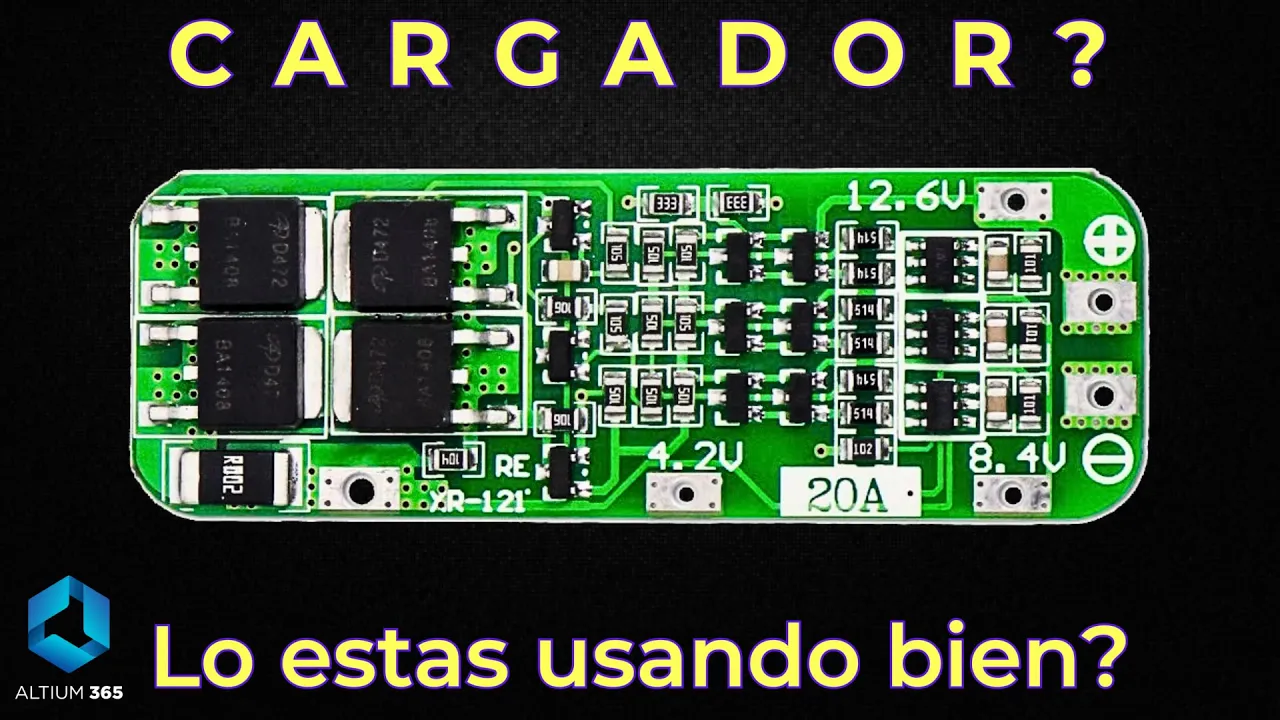
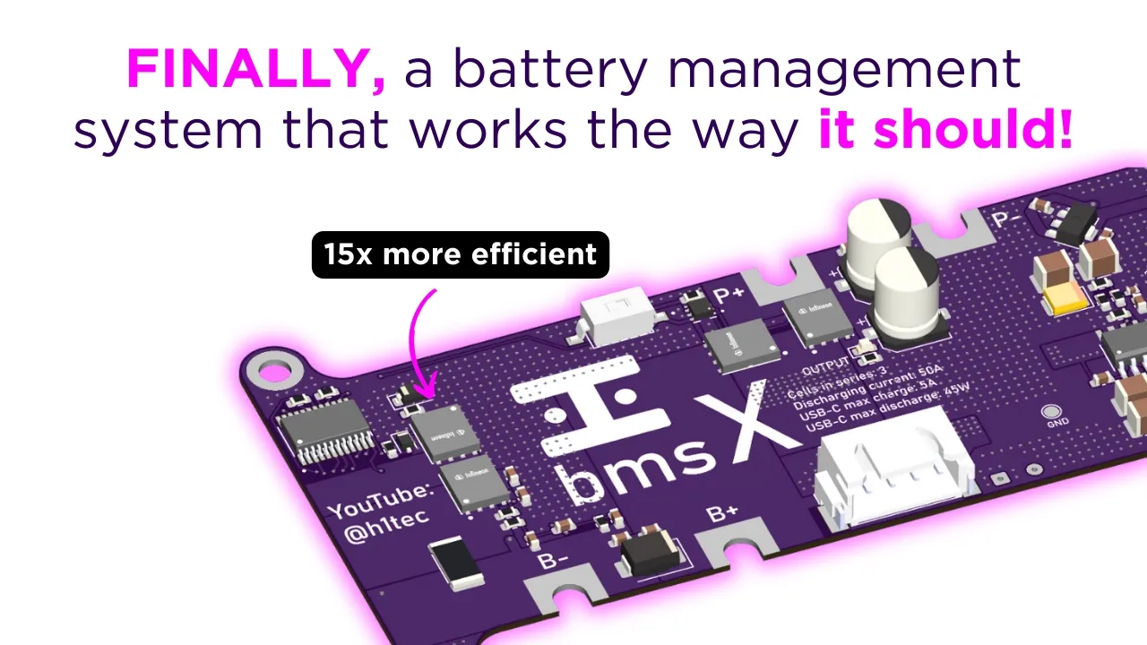
Uh if I drop the capacitor bank or something, this is probably going to crack. As well as when I glue on the last panel on the bottom, uh basically I can't get inside this box without cutting it open, which isn't exactly ideal. So why did I choose clear acrylic then? Well, it's a show piece. It's going to look good for a video. uh it's going to look good sitting on my bench and in the real world uh it's probably going to get broken at some point. So yeah, there's plenty of solutions to go build a box out of different materials and so forth. Um so feel free to use your own ingenuity ingenuity rather uh when it comes to um a box to mount everything in. So let's now get into the build. So let's take a brief moment to discuss what this balance board does exactly. Now in a circuit when we have capacitors in series like we're going to be wiring them, it's not a guaranteed fact that each cell will get exactly the same amount of voltage as each other cell in the circuit. Some charge at a slightly higher rate, some will charge at a slightly lower rate. So what this essentially means is that some cells in the circuit will be fully charged at their maximum voltage before others. Now why is this a problem? Well, essentially it prevents the whole bank from getting to their maximum voltage. Um and what this board does is help prevent overvolting as well. So if we were to hook up the circuit uh the um capacitor bank which in theory has a maximum voltage of 15 volts. So if we went over that threshold we would be at risk of damaging the cells. What this board does is help prevent that. It monitors the voltage on each individual cell. And if one of the cells in the circuit um begins to rise too high above its safe limit, this board will uh activate a semiconductor which then uh essentially burns off some of that excess voltage, bringing it back down to a safe level.
Don't however get complacent and think that this board is a superhero that will swoop in and save the day if you hook this up to 200 volts DC because this thing will die instantly. So treat it as a safety net, not an absolute protection.
And as you can see on the board, I've gone ahead and stuck down the um heat sinks on top of the semiconductors on this board. And that just helps dissipate some of the heat that they generate because they do get pretty toasty when they start to bleed off some of the excess voltage from the capacitors. So now let's take a look at the wiring loom. Now this might look a little bit intimidating at first, but it's actually very very basic. Now essentially we got the plug which plugs into our balance board and this has several connections terminated with some of the um lugs you saw at the start of the video. Now later on these will get bolted to the bus bars uh using these cap screws here. Um now when it comes to making up the leads as I already mentioned this is two gauge copper wire and they are terminated with uh heavy duty lugs. Now you can crimp these lugs on. However I do recommend soldering them because they give you an excellent connection. Um, but your typical garden variety soldering iron uh won't do a thing to heat this large copper lug up to a temperature that'll melt solder.
What you need is a soldering iron like this. Certainly not one you'd use to assemble electronic circuit board. This is 100 W. And you're also going to want some pretty hefty solder to match it. So that's what you're going to need to solder up the cables. And you don't need much cable. You can see I think if I bought half a meter of uh two gauge wire, it would have done both um connections. And we've also got a plug which plugs into the back of our voltmeter. You'll see how that goes together later on as well. So, we're going to put that to the side for the moment and we're going to work on assembling our capacitor bank.
So, let's have a quick look at these acrylic panels. Now, these are not mirror images of each other. They are both unique to one another. And essentially, they make it pretty easy to assemble the bank. Wherever you see a smaller hole between two larger holes, a bus bar gets installed in there. And that hole allows the uh long side of the cap screw just to poke out the back without any interference. So, it makes it quite easy to identify how everything goes together. And um basically, as you know, when we're wiring stuff in series, uh everything goes positive to negative, negative to positive, and so forth and so on. So, I'm going to take some of my bolts and washers. And I do want to make sure that uh when I'm installing a lug or a bus bar that it's making contact with the capacitor and that I haven't put it on the other side of the acrylic.
Uh this is going to give better surface area uh better contact uh to make an electrical connection with the capacitor naturally.
So, this is the first layer of the bank done. Um, so as you can see, positive, negative, negative, positive, and so forth and so on. And as I'm going along, I'm installing the um correct wires onto the bus bars so that our balance board can monitor each individual cell. So, I'll continue on the assembly and install the next layer of cells.
Right. So, here's the capacitor bank uh all finished and assembled. Now, the only reason I haven't bolted on this uh lug over here is before I put it into the box, this one's got to be bolted down to the terminal that mounts on the opposite side. otherwise things don't go together too well. Uh but for the moment that's the bank assembled. So we can move on to installing this in the enclosure. Now for my enclosure uh these get mounted top and bottom on the inside and these help support the capacitors and they get secured to the acrylic with countersunk screws. So I'll go ahead and install all these brackets now.
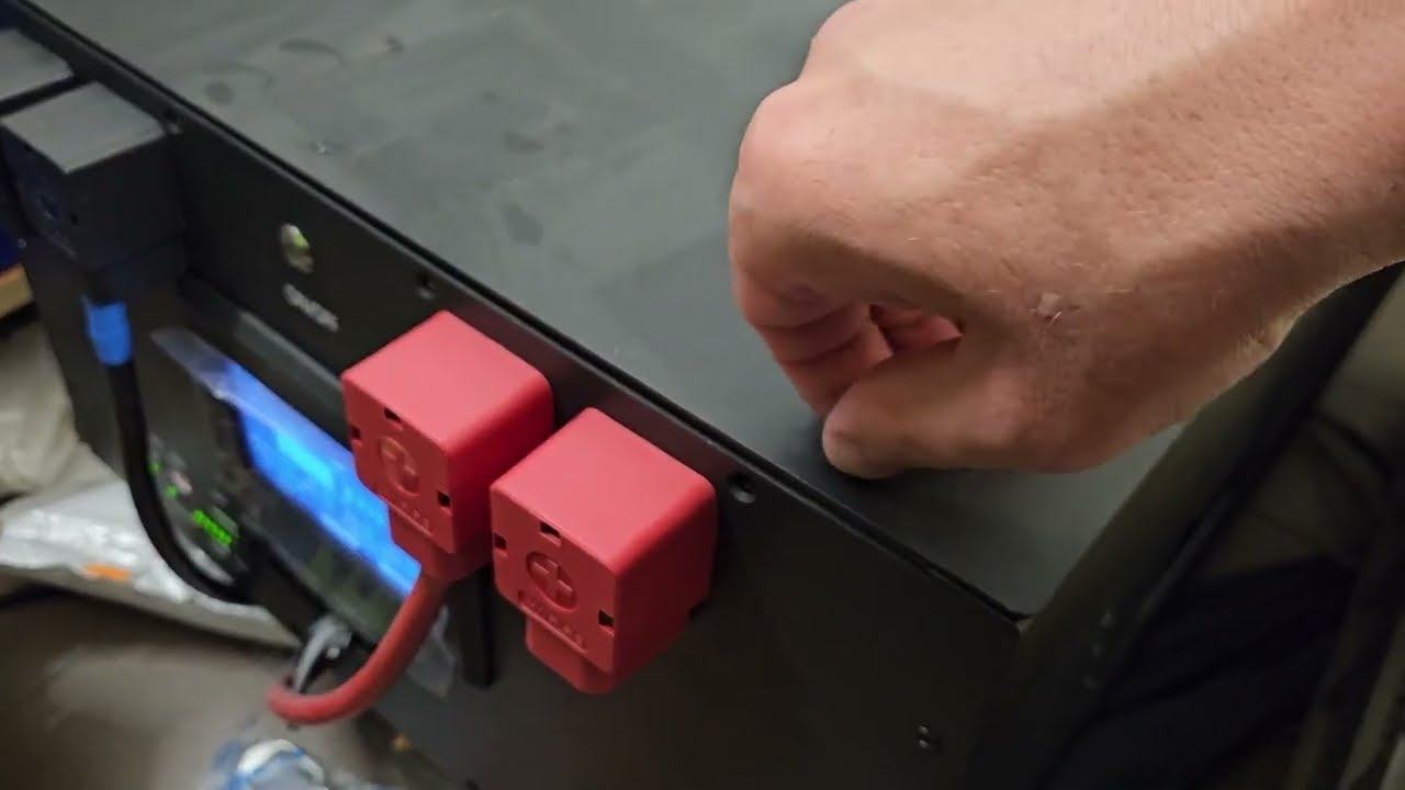
Now, inside the enclosure on the uh blue plastic brackets here, I've gone ahead and pre-installed some two-sided adhesive tape. Um, so it's not really there to uh securely mount the capacitors. It's just there to stop them uh from moving about any vibrations etc. if they're used in a motor vehicle. So before I can go ahead and install the capacitor bank inside my enclosure, I've got to first install the um battery lugs on the outside of the enclosure. Now when installing these, pay careful attention to what one is positive and negative because they are two different sizes. All right, so we're coming to the end of assembly now. So, I've got, as you can see, my battery lugs all installed. Uh, and I've installed the switch on the front. So, this switch activates the voltmeter. Now, this is rather uh pointless. You know, you don't really need either of these two components here. Uh, but it's just a nice feature I thought to add at the time. Um, so we're going to plug in our balance board now. And this gets installed on the front. As you can see in the corners, we've got brass M3 standoffs.
And this board rather awkwardly. We get everything out of the way.
Oh boy.
Gets installed like that. Doesn't that look just doesn't that look spectacular?
It's like watching a ballet, really, isn't it? It's so fancy.
So, I'll go ahead and install our voltmeter next. And this just snaps into place rather loudly. Um, and yeah, what next?
Well, I can probably start squishing everything together. That's going to look fun, isn't it? Right. So, with some gentle caressing with a hammer off camera, uh, I've got the capacitor bank mounted inside the box. And I'm not going to glue on the bottom panel and seal my fate at this point in time. I want to charge it up, uh, test it and everything. So, at the moment, I'm going to use duct tape to hold the bottom panel on while I'm doing tests. All right, so here's our capacitor battery bank um, fully assembled, minus the duct tape temporarily, of course. And for charging this, there's nothing really complicated about it. We need uh, a power supply between 12 and 14 volts DC, somewhere around there. And ideally you want something with uh current control and basically or constant current I should say. Basically these res uh these capacitors have almost no resistance.
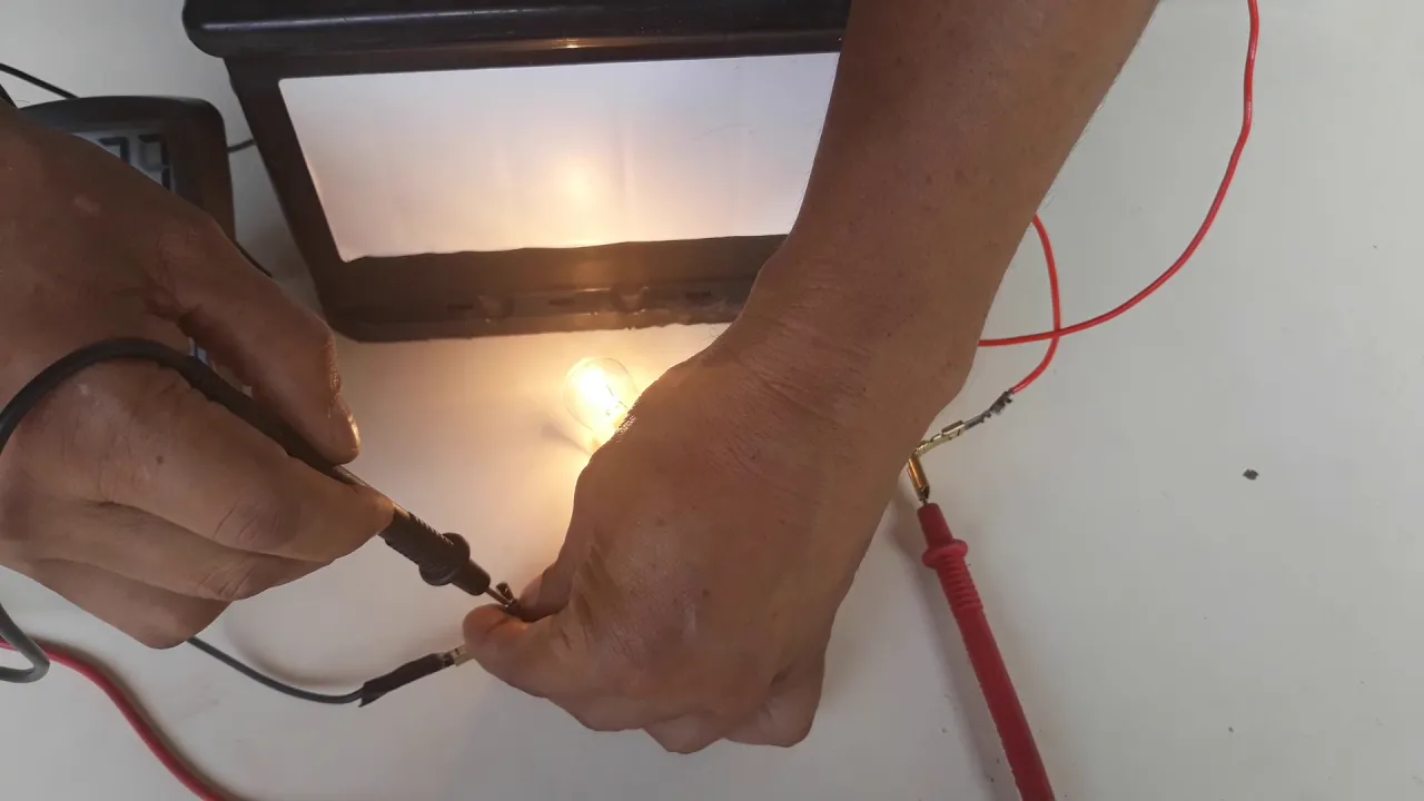
They're they're basically a dead short as far as a a normal battery charger would be concerned. And the risk involved with that is if we just hook it up to uh a normal charger um it can just take as much current as that charger can throw at it and potentially depending on the design of the charger that could damage it. Uh so I do recommend something with constant current control as I mentioned something like a lab power supply would be uh quite ideal at least for the initial charge because this thing is going to take a whopping amount of amps uh coming up from basically zero at the moment. And I got this charged to around 2 VTs. Uh so I'm going to bring that up to the uh or close to the full charge limit of this bank. So let's switch on the lab power supply. And I'm supplying it 12.1 volts for the moment. And I'm going to use this clamp meter here to measure how much current we're going to be feeding our uh capacitor bank.
So over here you can see the voltage immediately dropped u to about 2.6 volts during the charge cycle and we're currently feeding at about 4 1/2 amps.
And you know make no mistake these capacitors mean business. Uh if you're used to electronics and and you you've been in the business for years you know you don't see a lot of capacitors or capacitor banks even charging this slow.
Just look how slow this voltage is rising. Um, and how much current we're feeding it. So, I'm going to let this uh fully charge. I I should actually throw on a timer cuz that would be interesting to see.
I'll get out my cell phone and we'll see how long it takes to bring it up to around 12 volts.
So after about 12 minutes of charging and remember we didn't start from dead flat. It was around 2 1/2 volts. Uh we can see that the current is starting to taper off as the voltage of the bank uh starts to match that from the lab power supply.
Now you might think that this charge time is rather lengthly and at 12 minutes for a capacitor bank it is.
However, keep in mind what I mentioned earlier. Uh we can basically feed this a huge amount of current and um have it charged within a few seconds rather than a few minutes. However, place to be safe when doing the initial charge just for testing.
So, I've finished charging and testing my super capacitor bank and everything checked out good. So, I've gone ahead and glued on the bottom panel. So, now that is absolutely finished. Now, one other thing I did off camera is I got hold of uh some two gauge copper wire and made myself a set of jumper cables which can clamp onto the battery lugs on our super capacitor bank. Cuz perhaps the most handy use for myself will be to use the super cap bank as a jump starter for vehicles with flat batteries or maybe a tractor in winter that's needs a bit of help getting going. So, um, if you want to go and check out how well or how not well the Super Cap Bank performs, things like burning wire, dead shorting it, um, hooking up to a car, seeing how well it starts, then click the video link up in the top hand corner here and check out some of the destruction and mayhem. Other than that, thank you very much for watching. I'll see you in the next video. Bye for now.
Up Next
Regenerative Braking in Electric Vehicles Explained
@Sibs
80.1K views•2019-10-13

Ultrasonic Transducers: Resonant Frequency Measurement and Horn Design
@imajeenyus42
229.9K views•2017-02-22

Choosing Rectifier & Capacitor for AC-DC Conversion
@Schematix
238.4K views•2017-09-04

How a Student's Question Saved a NYC Skyscraper from Collapse
@veritasium
22.8M views•2025-04-26
Related Study Plans & Knowledge Roadmaps
Structured learning paths in Engineering