A breadboard is a reusable, solder-free platform for prototyping electronic circuits, featuring power rails on the sides for distributing power and terminal strips in the middle for connecting components horizontally in rows; when building circuits, components like LEDs (with longer pins being positive) and resistors are inserted into these strips, and Arduino code can control them by setting pins as outputs and using functions like digitalWrite() and delay() to create blinking effects.
How to Use a Breadboard for Electronics Prototyping and Arduino Circuits
Added:Deep Dive
Basic concepts of electricity, including voltage, current, resistance, and the application of Ohm's Law.

MODULO 1- CLASE 1- ELECTRICIDAD BASICA Y ELECTROMAGNETISMO
483
Voltage is electrical potential difference between two points - like height difference creating water pressure. Current flows only when voltage exists between points. Resistance opposes current flow: conductors (copper, silver) have low resistance; insulators (rubber, plastic) have high resistance; semiconductors (silicon) have intermediate conductivity. Ohm's Law states V = I × R, relating voltage, current, and resistance. This fundamental law enables circuit analysis and design.
Click to watch →

Ley de Ohm. Conceptos básicos y ejemplos.
2.5K
Ohm's Law (V = I × R) describes the fundamental relationship between voltage (V, measured in volts), current intensity (I, measured in amperes), and resistance (R, measured in ohms) in electrical circuits. The law states that voltage equals current multiplied by resistance, and can be rearranged to solve for any of the three variables: I = V/R or R = V/I. In a circuit, voltage represents the electrical potential difference that drives electrons through conductors, current is the flow rate of electrons through a conductor, and resistance is the opposition to current flow that converts electrical energy into other forms like heat. Practical applications include calculating current for a 10V source with 1000Ω resistance (I = 0.01A or 10mA), or determining the required voltage for a motor needing 5mA through 100Ω resistance (V = 0.5V).
Click to watch →

قانون أوم والمقاومة الكهربية | المحاضرة 3 | فيزياء 3ث 2026 ✅️✌️
429
Electricity is built upon three fundamental pillars: current (I), voltage (V), and resistance (R). Current is the flow of electric charge measured in Amperes using an ammeter connected in series. Voltage is the work done to move unit charge between two points, measured in Volts using a voltmeter connected in parallel. Resistance is the opposition to current flow, measured in Ohms. Conductors consist of positive ions fixed in place and free electrons that move throughout the material. When voltage is applied, electrons move in a specific direction, creating current. Resistance arises from collisions between moving electrons and the atoms/ions of the conductor. Resistors come in two types: fixed resistors with constant resistance values and variable resistors (rheostats) with adjustable resistance. A rheostat consists of a coil of wire with a sliding contact that changes the effective length of wire in the circuit. Ohm's Law states that at constant temperature, the voltage across a conductor is directly proportional to the current flowing through it (V = IR). This law is fundamental to understanding electrical circuits and applies to ohmic materials that follow this linear relationship.
Click to watch →

Current- Voltage- Resistance-Power- ohm’s law -laws of resistance
120
Electric current (I) is the flow of electric charge, with conventional current flowing opposite to electron movement. Voltage is the electric potential difference between two points, representing work done per unit charge. Ohm's Law states that voltage across a conductor is directly proportional to current, provided physical conditions and temperature remain constant. Electrical resistance is the property that opposes current flow, determined by four factors: resistance is directly proportional to the conductor's length and inversely proportional to its cross-sectional area.
Click to watch →

Basic Electrical & Electronics
148
Voltage is the difference in electrical potential between two points, measured in volts, and can be generated through friction, pressure, heat, light, chemical action, or magnetism; current is the rate of electrical charge flow measured in amperes; resistance, measured in ohms, opposes current flow and is affected by material properties, length, cross-sectional area, and temperature; these three quantities are related by Ohm's Law (V = I × R), which allows calculation of any one variable when the other two are known.
Click to watch →
Deep Dive
The fundamental structure of an electrical circuit, specifically the requirement of a closed loop and a path to ground.
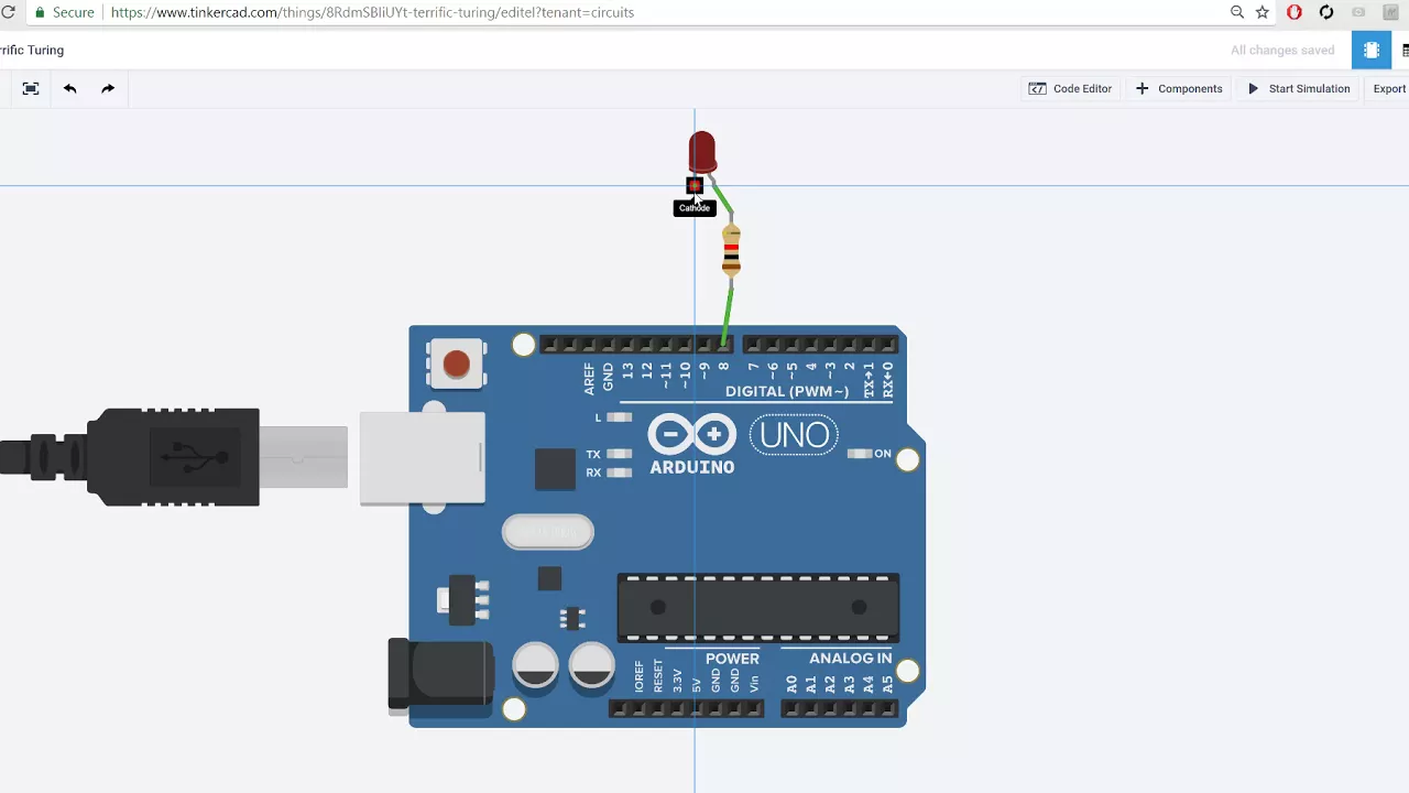
Arduino UNO Tutorial #1 - Intro to Arduino w/TinkerCAD Circuits
299.5K
All functional electrical circuits require a closed loop (complete path) for current to flow. In the Arduino circuit example, power connects from a digital port through a resistor to the LED's anode, then returns through the LED's cathode to ground. This creates a continuous path that enables current flow. Without a closed loop, the circuit cannot function properly regardless of how components are arranged.
Click to watch →

belajar hardware sama @ArtificialPortal & @andhikanug
66.8K
Electrical circuits require a complete loop for current to flow from the power source through components and back. Ground (GND) serves as the reference point in circuits, similar to earth ground in household wiring. Batteries have positive and negative terminals, and components like LEDs also have polarity. Current flows from positive to negative, and circuits must be complete for current to flow. Without a complete circuit, components cannot function.
Click to watch →

We address some LS wiring issues!
108
Electrical circuits require a complete closed loop for proper function. The circuit consists of a voltage source (battery), a work component (such as fuel pump or ECU), and a ground path that returns current back to the battery. If the circuit is not properly grounded or has loose connections, the system will malfunction. The ground provides the return path for electrons to complete the circuit back to the battery.
Click to watch →
🔴Circuit and Its Elements | परिपथ व उसके अवयव | Lesson-1 | Complete Theory | Electrical Special
15.5K
A circuit is a combination of two or more elements that creates a closed loop for current flow. The essential requirement is a closed path where current can travel from the starting point, through components, and return to the origin. A circuit requires a minimum of two elements: one energy source and one energy load. Without a closed loop, current cannot flow and the circuit cannot function.
Click to watch →

EGR201 Lec1 Electrical Fundamentals I
713
An electric circuit is an interconnection of electric components in a closed path. The closed path is essential for current to flow from the power source through components and back. Without a complete return path, the circuit cannot operate. The return path may be visible wires or may use the device's chassis or body as ground. This concept is fundamental to understanding how electrical devices function.
Click to watch →
Deep Dive
Identification and basic function of simple electronic components, particularly resistors, LEDs, and jumper wires.
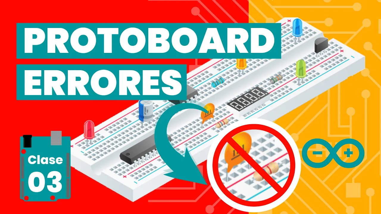
💡 Cómo usar un PROTOBOARD Arduino desde CERO【 2021 】 - Capítulo #03🔋
352K
LEDs have polarity: the longer lead is positive (anode), the shorter is negative (cathode). Connecting LEDs backwards prevents operation. Resistors limit current to protect components like LEDs from excessive voltage. Proper resistor handling involves gripping by the ceramic body and bending legs individually. Jumper wires follow a color convention: dark colors for ground/negative, light colors for positive. These components form the basic building blocks for Arduino projects.
Click to watch →

Class 9 Tech ICT Chapter 2 Lecture 3 | Resistors and Jumper Wires Explained | Punjab Board #
240
Resistors are electronic components that create resistance to control and limit the flow of electric current in circuits, protecting components like LEDs from excessive current; they are identified by color bands where 4-band resistors use the first two bands for digits, third for multiplier, and fourth for tolerance, while 5-band resistors use the first three bands for digits, fourth for multiplier, and fifth for tolerance. Jumper wires are flexible wires used to connect components on breadboards and circuits, available in four types: male-to-male (pins on both ends), male-to-female (pin on one end, socket on other), female-to-female (sockets on both ends), and solid core (single stiff wire inside plastic coating), each serving different connection purposes in electronic prototyping.
Click to watch →
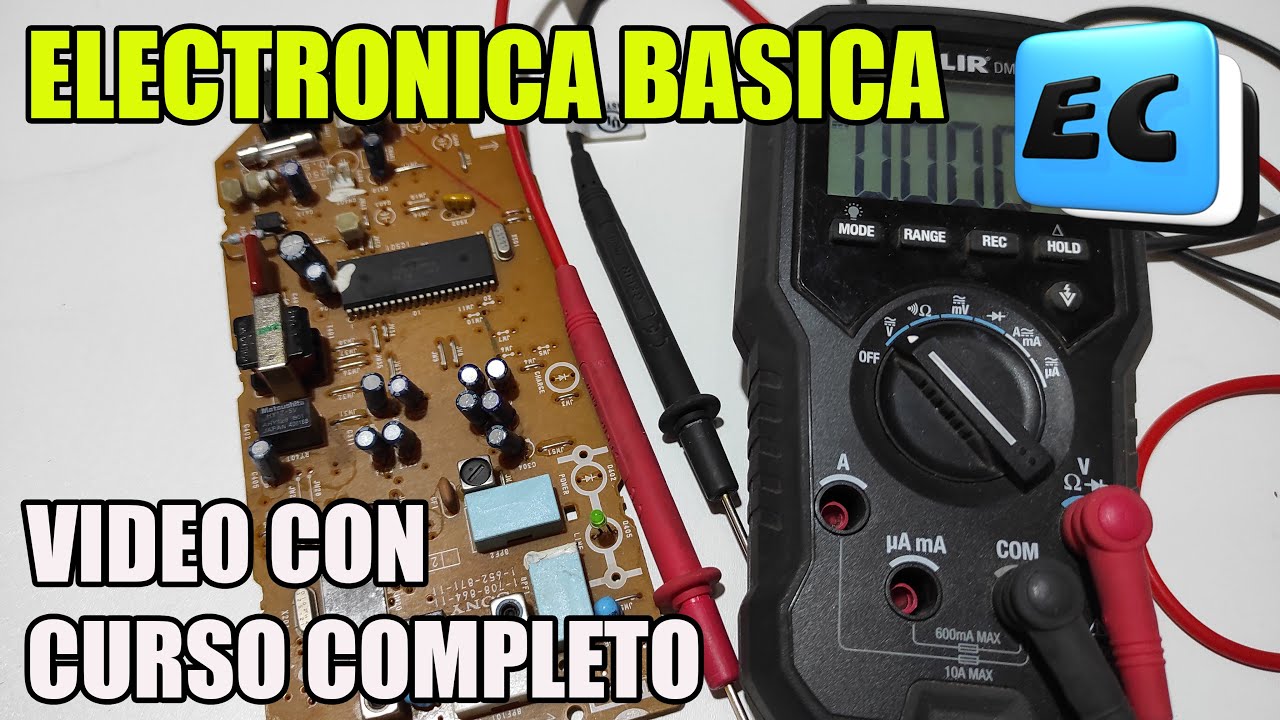
APRENDE YA!!! Electrónica desde CERO! - Curso Completo GRATIS
57.1K
Resistors oppose current flow and use color codes: first two bands are digits, third indicates zeros, fourth shows tolerance (gold=±5%, silver=±10%). Modern SMD resistors use numerical codes like '103'=10,000Ω. Capacitors store charge—electrolytic are polarized, ceramic use similar codes (104=100,000pF=100nF). Transistors have three pins and require datasheet lookup for pinout (NPN/PNP types). Integrated circuits contain thousands of components in single packages. Diodes allow one-way current flow; LEDs emit light. Relays use electromagnetic coils to control contacts. Each component type has distinct physical characteristics and schematic symbols essential for circuit analysis and repair.
Click to watch →

หน้าที่ของชิ้นส่วนอิเล็กทรอนิกส์พื้นฐาน ตอนที่ 1 ตัวต้านทาน และไดโอด (วิทยาศาสตร์ ม. 3 เล่ม 2)
85.4K
Resistors control the amount of current flowing through a circuit by providing resistance, with fixed resistors having constant resistance values read from color codes (e.g., brown-black-red-gold = 1000Ω ±5%) and variable resistors allowing continuous adjustment of resistance; diodes allow current to flow in only one direction, with LEDs specifically requiring correct polarity (shorter leg to negative terminal) to emit light, and both components are essential for protecting electronic circuits from excessive current.
Click to watch →

Little Scientist #8: LED Light Glove
1.1K
A 1000 ohm resistor is used to limit the electrical current flowing through the LED circuit, preventing the LED from burning out. Jumper wires are short conductive wires used to connect components together in electronic circuits. Three jumper wires of approximately 20 cm length are needed for this project.
Click to watch →
Deep Dive
An introductory understanding of the Arduino hardware platform, including how to connect it to a computer and upload a basic sketch.
![Ардуино уроки программирование для начинающих с 9 лет [с нуля] #ДомаВместе](https://i.ytimg.com/vi/RwO_4nhRTUM/maxresdefault.jpg)
Ардуино уроки программирование для начинающих с 9 лет [с нуля] #ДомаВместе
114.8K
Arduino is designed for absolute beginners with zero programming experience, requiring only basic skills like adding numbers and installing apps. The platform eliminates the need to understand complex physics before starting projects. Hardware requirements include an Arduino board (Uno or Nano), a computer with any operating system, and a USB cable. Arduino uses a simplified C++ programming language. The platform offers various board types: standard boards with larger labels and external power connectors, and Nano boards for cost savings. Both original and clone boards work for beginners. For connectivity, use a USB cable from a printer or scanner (Type B connector), with USB Mini-B for Nano boards. Install Arduino IDE from the official website, choosing between classic installer or portable version. Accept the free license agreement, select software, drivers, shortcuts, and file association for .ino files. Connect Arduino via USB to a computer port (prefer rear ports for better connection quality). The board's LED indicators confirm power status. Select the correct COM port in Tools > Port menu. Arduino boards contain USB-to-COM converters, making port selection necessary. COM port numbers can change when moving to different USB ports.
Click to watch →

3- ربط الأردوينو بالحاسوب | Connecting Arduino to Computer
3.1K
To connect Arduino to a computer, first install the Arduino IDE software from the official website, then connect the Arduino via USB cable, select the appropriate board type (e.g., Arduino Uno) and the correct COM port in the Arduino IDE settings, and finally test the connection by uploading the Blink example sketch which should cause the Arduino LED to blink successfully.
Click to watch →

Arduino Programming Masterclass: From Basics to Libraries in 90 Mins
3.6M
Arduino is an open-source platform for controlling electronic devices using code, serving as an intermediary between input sensors (temperature, light, touch, distance) and output devices (motors, LEDs, speakers, displays). The ecosystem requires three components: hardware (physical boards), the Arduino IDE (software for writing code), and Arduino code (called sketches). The Arduino Uno Rev 3 is recommended for beginners with 20 GPIO pins and standard shield compatibility. Boards can be powered via USB, DC jack (7-20V, max 12V recommended), or external VIN pin. The microcontroller processes code, while pin headers enable temporary connections without soldering. The Arduino IDE enables writing and uploading code to boards, with versions including Arduino IDE 1, Arduino IDE 2, and a web editor. Installation creates a sketchbook folder storing projects and libraries. The workflow involves connecting via USB, selecting board type under Tools > Board, choosing COM port under Tools > Port, clicking Verify to compile and check errors, then clicking Upload.
Click to watch →

Getting Started with Arduino: A Deep Dive for Beginners
519
Connecting Arduino to a computer involves plugging the USB cable and selecting the correct port (COM number) in the Arduino IDE. The computer recognizes the Arduino and displays indicator lights. Users must also select the correct board type from the Arduino website. Program upload transfers code from the computer to the Arduino hardware. Successful upload shows no errors, with RX/TX lights blinking briefly. The test program controls an LED on pin 13, demonstrating hardware-software communication.
Click to watch →
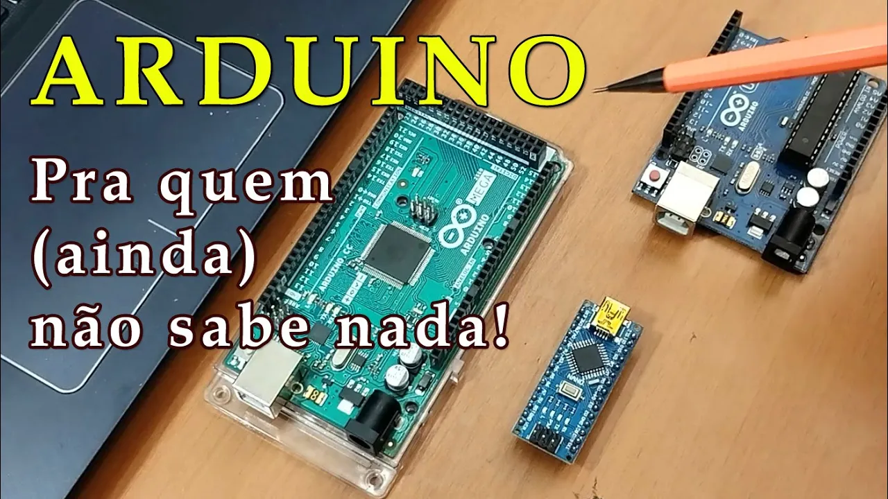
Arduino pra quem não sabe nada (mas tem vontade de saber) #Arduino 1
10.3K
Arduino is a widely-used microcontroller platform designed for electronic projects, accessible to beginners while supporting advanced users. The platform enables creation of various devices like LED controllers, CAN network controllers, and fuel injection systems. The hardware consists of a microcontroller chip (brain), standardized I/O ports, USB connectivity, and modular expansion through Shields. Three main board models exist: Arduino Uno (ATmega328, 14 digital/6 analog ports, most traditional), Arduino Nano (compact, prototyping-friendly), and Arduino Mega 2560 (ATmega2560, 54 digital/16 analog ports, highest capability). The Arduino IDE (Integrated Development Environment) is the software for programming, available in versions 1.8.19 (stable, classic) and 2.0 (modern with auto-completion). Installation follows standard Windows procedures. After installation, connect the Arduino via USB; Windows automatically recognizes original boards and installs drivers. Verify installation through Device Manager (devmgmt.msc), locating the Arduino under Ports (COM & LPT) and noting the COM port number. Configure the IDE by selecting the COM port under Tools > Ports and the board model under Tools > Board. The Blink sketch is the simplest Arduino program, causing the built-in LED (pin 13) to blink.
Click to watch →
Prerequisite Knowledge
- Concept 01Basic concepts of electricity, including voltage, current, resistance, and the application of Ohm's Law.
- Concept 02The fundamental structure of an electrical circuit, specifically the requirement of a closed loop and a path to ground.
- Concept 03Identification and basic function of simple electronic components, particularly resistors, LEDs, and jumper wires.
- Concept 04An introductory understanding of the Arduino hardware platform, including how to connect it to a computer and upload a basic sketch.
Subsequent Learning
- Step 01Interfacing basic sensors (such as photoresistors or thermistors) to read analog and digital inputs on the Arduino.
- Step 02Controlling high-current actuators like DC motors or servos, which involves learning about transistors, relays, and external power supplies.
- Step 03Utilizing integrated circuits (ICs) like shift registers or motor drivers to expand the prototyping capabilities on the breadboard.
- Step 04Transitioning from temporary breadboard prototypes to permanent electronics projects using soldering techniques, stripboards, or custom Printed Circuit Board (PCB) design.
Breadboard Basics
Blink Coding
Breadboard Basics
0:02Playing Section
- 1
Explains breadboard structure and power rail usage.
- 2
Details terminal strips connecting components in rows.
- 3
Mentions common sizes and middle gap separation.
The Limitations of Solderless Breadboards and the Case for Soldered Prototyping
While solderless breadboards are popular for beginners and simple Arduino projects, they pose significant limitations for advanced or reliable prototyping. Solderless breadboards introduce high parasitic capacitance, contact resistance, and stray inductance, which can severely degrade signal integrity in high-frequency, RF, or fast digital circuits. Additionally, the temporary spring-clip connections are prone to loosening, leading to intermittent connection failures that are notoriously difficult to debug. Critics argue that relying too heavily on breadboards can teach poor circuit design habits. Instead, they advocate for alternative methods like soldered perfboards (stripboards), 'dead bug' prototyping, or rapid-turnaround custom Printed Circuit Boards (PCBs). These alternatives provide superior mechanical stability, reliable electrical connections, and realistic circuit behavior, making them essential for moving beyond basic hobbyist projects into professional-grade electronics.
Deep Dive
Interfacing basic sensors (such as photoresistors or thermistors) to read analog and digital inputs on the Arduino.
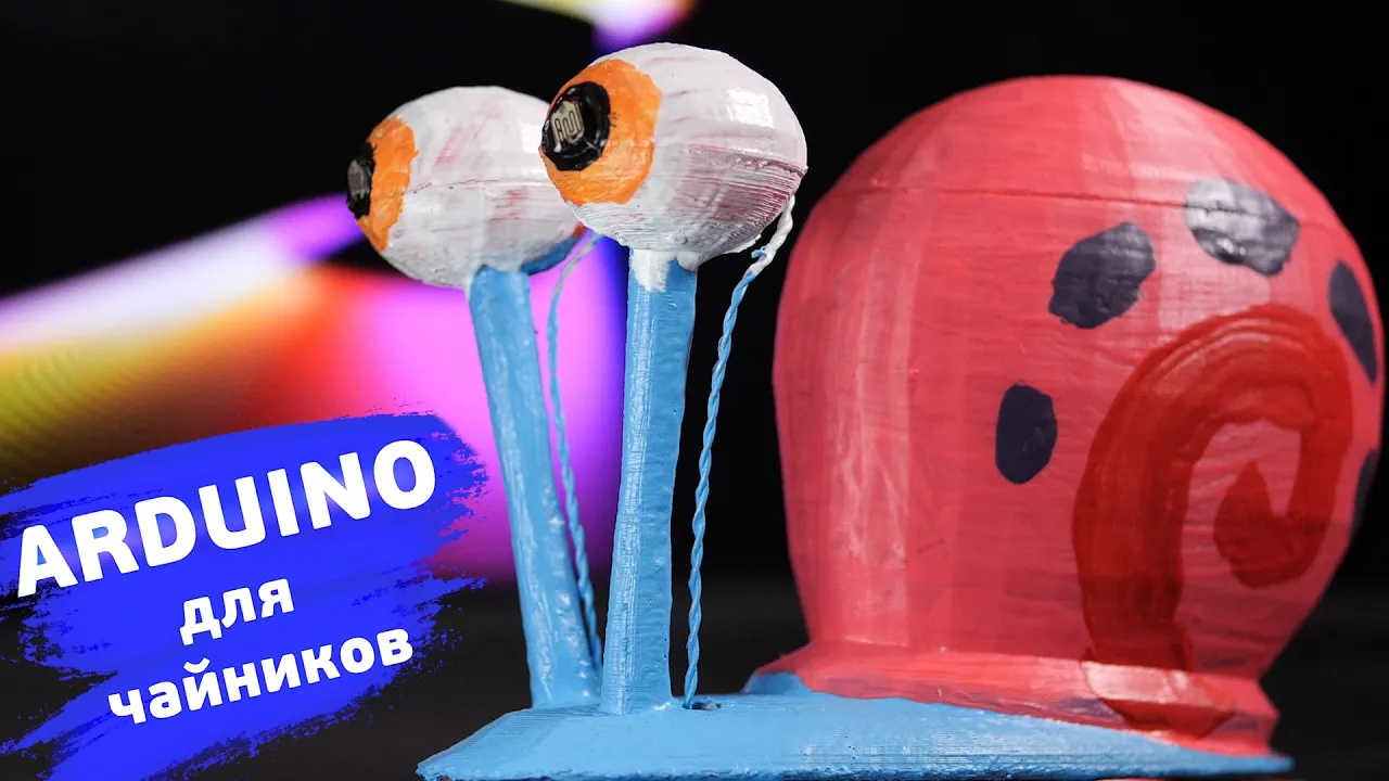
Что такое термистор и фоторезистор — эксперименты с теплом и светом. Понятные уроки по Arduino
84K
This extensive section covers the complete process of integrating sensors with Arduino microcontrollers. The video demonstrates building a voltage divider circuit using a thermistor and 10kΩ resistor, connecting it to Arduino's analog input pin (A0). The Arduino's ADC converts analog voltage readings into digital values (0-1023), which are then scaled using the map() function to appropriate ranges (0-255 for LED brightness). PWM (Pulse Width Modulation) controls LED brightness by rapidly switching the LED on and off at different duty cycles. The section then introduces photoresistors, showing they can replace thermistors in identical circuit configurations since Arduino reads changing resistance regardless of the cause (temperature or light). Practical applications include light-sensitive robots with photoresistor 'eyes' that detect and respond to light sources. The video emphasizes that the same Arduino program structure works for both sensor types, with only the physical component changing.
Click to watch →

O Level Practical Marathon 2026 | PR4 IOT | M4 R5 PRACTICAL | O Level IOT Practical #pr4
16.7K
Arduino can read both analog and digital sensors using different functions. Analog sensors (like soil moisture, LDR) use analogRead() which returns values 0-1023. Digital sensors (like buttons, IR sensors) use digitalRead() which returns HIGH or LOW. Pin mode must be configured for digital sensors using pinMode(). Serial Monitor helps debug by displaying sensor readings. This knowledge applies to various sensor types in IoT projects.
Click to watch →
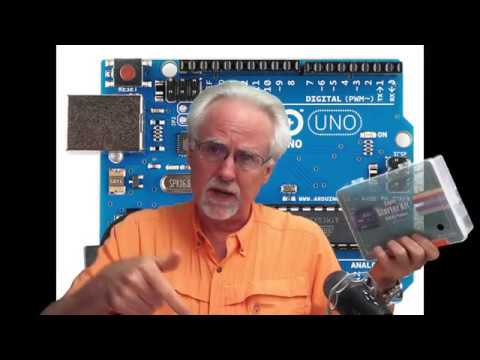
Arduino Tutorial 25: Understanding Photoresistors and Photo Detectors
227.9K
A photoresistor is a semiconductor device whose electrical resistance decreases as light intensity increases, due to photons generating electron-hole pairs that enable conduction; to measure this resistance change with Arduino, connect the photoresistor in series with a fixed resistor (5kΩ) between 5V and ground, then read the voltage at the junction using an analog pin, where higher light levels produce higher voltage readings (around 700) and lower light levels produce lower readings (around 200), allowing the Arduino to control LEDs based on detected light conditions.
Click to watch →
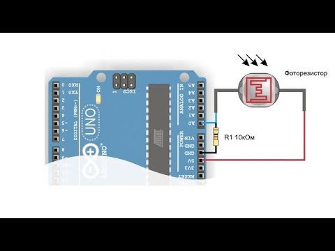
Урок 9 Подключение фоторезистора к Arduino
20.8K
A photoresistor is connected to Arduino by wiring one leg to 5V and the other leg to an analog input pin (A0), with the same leg also connected through a 10kΩ resistor to ground; Arduino reads the analog voltage value (0-1023) which changes inversely with light intensity (higher light = lower resistance = lower voltage), allowing the microcontroller to detect light levels and trigger actions like turning on an LED when the reading falls below a threshold value (e.g., 500).
Click to watch →
كيف تبرمج الأردوينو؟ وتعلم اساسيات الالكترونيات
939
To read digital inputs, use pinMode() to configure pins as INPUT or OUTPUT, then digitalRead() which returns 1 (HIGH) or 0 (LOW). To read analog inputs, use analogRead() which returns values from 0-1023 (10-bit resolution, representing 0-5V). This allows reading sensors like potentiometers, light sensors, and temperature sensors that produce continuous voltage signals. Proper circuit design with pull resistors ensures stable input states.
Click to watch →
Deep Dive
Controlling high-current actuators like DC motors or servos, which involves learning about transistors, relays, and external power supplies.
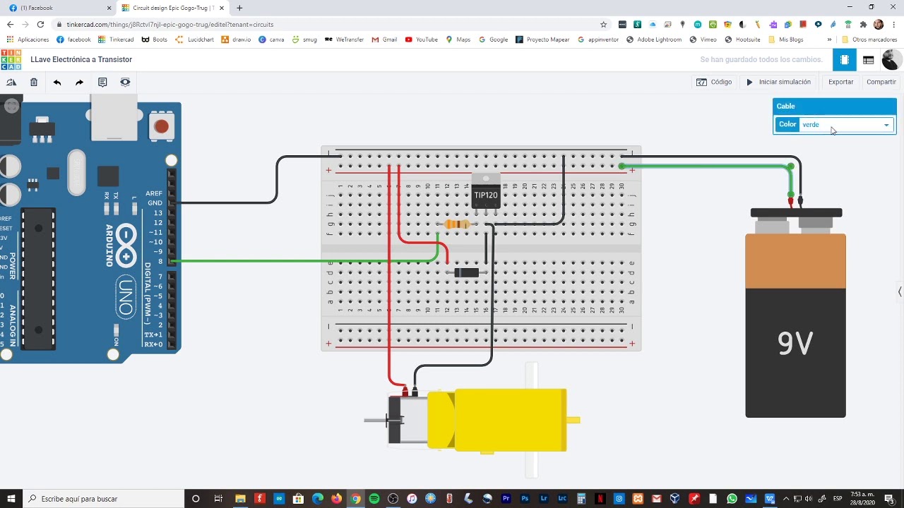
llave electrónica a transistor
209
Electronic switches (transistors) enable Arduino to control high-current actuators safely. For DC circuits, transistors are used; for AC circuits, relays are required. The TIP120 power transistor handles currents from 1A to 20A by using a small base current to control a large collector current. The transistor's three terminals are: base (input), collector (output to load), and emitter (ground connection). A 330-ohm resistor limits base current from Arduino pins. This approach protects Arduino from damage while enabling control of motors and other high-power devices.
Click to watch →

التحكم بالاجهزة بالترانزيزتور و الريلي #transistor #relay #اردوينو #رازبيري #diy
608
When controlling high-power devices like motors or appliances with microcontrollers such as Arduino, transistors and relays are essential because microcontrollers cannot directly supply the high current required; transistors can handle up to 800mA or several amperes for DC circuits, while relays can switch AC devices up to 250V and 18A, making them suitable for appliances like air conditioners and refrigerators.
Click to watch →

''Electrical Actuator'' Mechatronics By Mr Puneet Saini, AKGEC
186
Electrical actuators convert electrical energy into mechanical motion; key components include relays (electromagnetic switches with coils, armatures, contacts, and springs that use electromagnetic principles to control high-current circuits), solenoids (insulated copper coils wound around cylindrical tubes that attract ferrous cores to perform linear motion for fluid control applications), and DC motors (which operate on the principle that current-carrying conductors in magnetic fields experience force, with commutators reversing current direction every half-revolution to maintain continuous rotation and generate back EMF that makes them self-regulating machines).
Click to watch →

Como Controlar Circuitos com Muita Corrente ? - Vídeo #2
18.4K
Relays are electromechanical switches that can handle much higher currents (up to 10A or more) than transistors. They can switch both DC and AC circuits, including mains voltage (110V/220V). Relays are particularly useful for controlling high-power devices like lamps, motors, or appliances that exceed transistor current capabilities. The relay coil is controlled by a transistor, while the relay contacts switch the load circuit.
Click to watch →
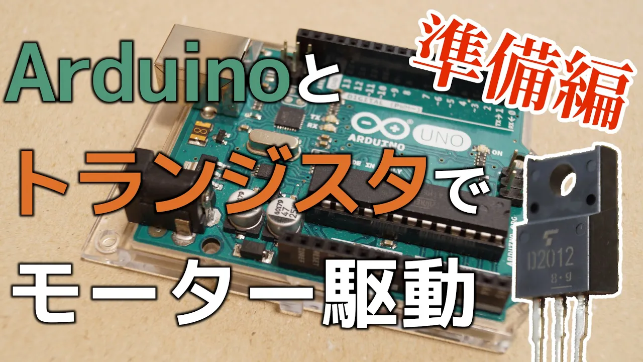
【トランジスタの役割】 Arduinoとトランジスタでモーター駆動 準備編
4.8K
Microcontrollers like Arduino cannot directly power motors due to current limitations. A motor requiring 500mA cannot be driven by an Arduino IO pin limited to 40mA. Transistors solve this problem by amplifying current: they take a small input current from the microcontroller and control a much larger current from an external power source. The Hfe (DC current gain) parameter determines amplification ratio, such as 200:1. The total output current equals the input current plus the current drawn from the external power supply. Transistors also function as electronic switches, enabling high-power loads with minimal microcontroller current. This allows driving motors and other high-power devices using low-power microcontrollers.
Click to watch →
Deep Dive
Utilizing integrated circuits (ICs) like shift registers or motor drivers to expand the prototyping capabilities on the breadboard.

آیسی ها با زبانی ساده | تحلیل آیسی شیفت رجیستر
11.1K
Interface ICs enable communication between incompatible systems through signal conditioning, level conversion, and protocol translation. Shift register ICs (74HC595) expand microcontroller I/O capability using serial-to-parallel conversion, controlling 8 outputs with only 3 microcontroller pins. Key control pins include DS (data input), SHCP (shift clock), STCP (storage clock), OE (output enable, active-low), and MR (master reset, active-low). Multiple registers cascade by connecting Q7' of one to DS of the next, enabling hundreds of outputs with minimal pin usage. This architecture solves microcontroller pin limitation problems in LED displays, motor drivers, and relay arrays.
Click to watch →

How to use breadboard, very easy to understand breadboard
160.7K
Integrated Circuits (ICs) should always be placed in the middle section of the breadboard where a complete empty slot is available. The middle section provides a full slot for the IC, and since there is no connection between the upper and lower power rails, the IC can be placed in either the upper or lower middle section without electrical interference between the two halves.
Click to watch →

Why the 74HC595 is Your Next Favorite IC?
116.8K
The 74HC595 is an 8-bit serial-in parallel-out shift register IC that expands microcontroller I/O pins by allowing multiple displays to be controlled through just 3 pins (data input, clock, and shift register output), with data loading into internal memory via serial input and clock pulses, and data transfer to outputs via a separate clock pulse, making it ideal for driving multiple seven-segment displays without consuming excessive microcontroller pins or causing flickering during video recording.
Click to watch →

Temperature Based Fan Speed Controller Using Arduino UNO || ARDUINO PROJECTS
174.8K
The motor driver's 5V pin connects to the positive line of the breadboard, and the ground wire connects to the ground line of the breadboard. This ensures the motor driver receives stable power from the same source as other components on the breadboard.
Click to watch →

AIWA 3 Head Tape Deck (AD-F990) Part 2
241.4K
Before committing to custom PCB fabrication, electronics technicians should prototype new motor control circuits on a breadboard to verify functionality. The video shows building a simplified four-pin motor driver circuit using an NJM4560 op-amp. Key connections include: pin 1 (12V supply), pin 2 (resistor to ground), pin 3 (ground), pin 4 (output with trim pot for speed adjustment). A current draw of approximately 6mA indicates proper operation. This prototyping step helps identify design issues before investing in custom board manufacturing.
Click to watch →
Deep Dive
Transitioning from temporary breadboard prototypes to permanent electronics projects using soldering techniques, stripboards, or custom Printed Circuit Board (PCB) design.

Custom PC Keypad - Microcontroller Project
46.6K
This section illustrates the progression from initial breadboard prototyping to permanent circuit board assembly in electronics projects. The video demonstrates transitioning from temporary breadboard connections to soldered permanent circuits on stripboard. Key techniques shown include soldering headers to microcontroller sides, mounting components underneath the microcontroller to save space, using blue tape for temporary component mounting during testing, and adapting to less-than-ideal board layouts when ideal materials aren't available. The section emphasizes that functional operation takes precedence over aesthetic perfection in prototype development, with the goal being reliable operation rather than competitive circuit board presentation.
Click to watch →
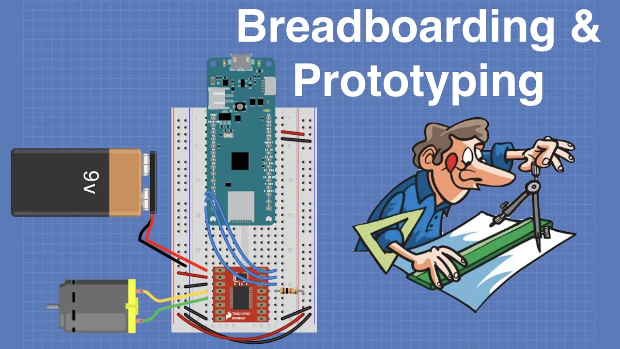
Breadboarding & Prototyping for Electronics, Arduino & Raspberry Pi
132K
Successful prototypes transition from breadboard to permanent construction using perfboard or printed circuit boards. Perfboard serves as an intermediate step for testing layouts and making modifications before PCB fabrication. Quality perfboard uses glass epoxy with plated-through holes for reliable connections. IC sockets enable easy component replacement. Wire gauge selection (wire wrap for signals, 22 AWG for power) ensures proper current handling. Perfboard experience informs PCB layout decisions.
Click to watch →

Creating Your Own Printed Circuit Boards
103.5K
Printed circuit boards (PCBs) provide a permanent, organized solution for electronic projects that have become messy 'Rat's Nests' with wires everywhere. PCBs allow components to be soldered directly onto a board with pre-defined connection points, eliminating the need for breadboards and jumper wires. This transition from breadboard to PCB represents a significant step forward in electronics prototyping, offering durability, professional appearance, and improved reliability for electronic projects.
Click to watch →
Ben Heck's Design Workflow Episode
42.8K
This section covers the progression from breadboard prototyping to perf board design. Breadboards feature horizontal connections for component pin access and vertical power rails (blue/red) for power distribution, with broken horizontal connections allowing chips to straddle the board. Perf boards require careful component layout before soldering, use sockets for easy chip replacement, and employ color-coded power buses (black=ground, red=5V, yellow=12V). Hot glue secures connectors and bundles wires. Solid strand wire positions more reliably than stranded wire. This progression enables designers to move from quick testing to permanent installations.
Click to watch →

How To Build Circuits On Stripboard or Veroboard
126.9K
This tutorial demonstrates how to construct a 555 timer-based LED flasher circuit on stripboard (veroboard), covering essential skills including board cutting, component placement, soldering techniques, track cutting, and circuit troubleshooting using a multimeter.
Click to watch →
Breadboard Basics
Blink Coding
Breadboard Basics
0:02- 1
Explains breadboard structure and power rail usage.
- 2
Details terminal strips connecting components in rows.
- 3
Mentions common sizes and middle gap separation.
The Limitations of Solderless Breadboards and the Case for Soldered Prototyping
While solderless breadboards are popular for beginners and simple Arduino projects, they pose significant limitations for advanced or reliable prototyping. Solderless breadboards introduce high parasitic capacitance, contact resistance, and stray inductance, which can severely degrade signal integrity in high-frequency, RF, or fast digital circuits. Additionally, the temporary spring-clip connections are prone to loosening, leading to intermittent connection failures that are notoriously difficult to debug. Critics argue that relying too heavily on breadboards can teach poor circuit design habits. Instead, they advocate for alternative methods like soldered perfboards (stripboards), 'dead bug' prototyping, or rapid-turnaround custom Printed Circuit Boards (PCBs). These alternatives provide superior mechanical stability, reliable electrical connections, and realistic circuit behavior, making them essential for moving beyond basic hobbyist projects into professional-grade electronics.
Basic concepts of electricity, including voltage, current, resistance, and the application of Ohm's Law.
The fundamental structure of an electrical circuit, specifically the requirement of a closed loop and a path to ground.
Identification and basic function of simple electronic components, particularly resistors, LEDs, and jumper wires.
An introductory understanding of the Arduino hardware platform, including how to connect it to a computer and upload a basic sketch.
Interfacing basic sensors (such as photoresistors or thermistors) to read analog and digital inputs on the Arduino.
Controlling high-current actuators like DC motors or servos, which involves learning about transistors, relays, and external power supplies.
Utilizing integrated circuits (ICs) like shift registers or motor drivers to expand the prototyping capabilities on the breadboard.
Transitioning from temporary breadboard prototypes to permanent electronics projects using soldering techniques, stripboards, or custom Printed Circuit Board (PCB) design.
880 views37likes4:03@Mr.AtechsOriginal Release: 2024-09-25
the most essential tool for any Electronics project the bread board if you're new to electronics you've probably heard of a breadboard a breadboard is a simple platform that let us build circuits without the need for soldering it's perfect for prototyping and testing designs because it's reusable and flexible a typical breadboard has two main areas the power rails on the sides and the terminal strips in the middle the power rails run vertically and are usually labeled with positive and negative signs they're used to distribute power to different parts of the circuit you can connect your battery or power source here in the middle we have the terminal strips these holes are connected horizontally in rows when you insert the components into these holes it's connected to all other components in the same row bread boards come in different sizes to fit different projects but the most common size is the medium size breadboard [Music] in the simple circuit we will use an ordino UNO a breadboard an LED and a 220 ohm resistant [Music] [Music] it's important to note that the middle Gap often called the trench separates the two sides of the Bread [Music] Board you might already know this but let's mention it anyway the longer pin of the ledd is positive the shorter pin is negative don't forget it [Music] we are done with the circuit let's start coding now I set pin 8 as an output this means that later I'll be able to turn things on or off using this pin [Music] here I'm setting pin a to high which means I'm telling the ardino to send five FS out of this [Music] spin now let's make it blink I'm just adding a delay function [Music] here and copy past this [Music] row and also I add DeLay So that our LD works [Music] [Music] properly thanks for watching he
Up Next
13:54
Arduino UNO Tutorial for Beginners: Complete Guide (Part 1)
@ElectroSpark-y5i
254 views•2025-06-18

12:54
Triumph of Orthodoxy Icon: Byzantine Art & History Explained
@BenCallan
2.1K views•2024-08-06

9:49
FastAPI vs Flask vs Django: Choosing the Right Python Web Framework
@TechWithTim
302.5K views•2024-05-26

1:42
Game of Thrones Opening Credits: A Cinematic Analysis
@gameofthrones
46.3M views•2011-04-18
Related Study Plans & Knowledge Roadmaps
Structured learning paths in General & Interdisciplinary Studies
general-studies
Elevator Engineering: History, Physics & Cities
01From Hoists to Safety Brakes: The Dawn of Vertical Lift
02Hydraulic vs. Traction: The Engineering Physics of Elevators
03Modern Speed, Safety, and Algorithms
+ 2 more learning modules
12h5 modules
Explore Roadmap
general-studies
Rubber: Material Science, History & Geopolitics
01Origins of Natural Rubber & Mesoamerican History
02The Chemistry of Natural Rubber & Vulcanization
03The Geopolitics of the Rubber Boom & Colonization
+ 2 more learning modules
12h5 modules
Explore Roadmap
general-studies
Containerization: Evolution, Logistics & Trade
01Ancient Trade & Bulk Cargo: Amphorae to Barrels
02The Industrial Revolution & Cardboard Packaging
03The Containerization Revolution: Malcom McLean
+ 2 more learning modules
12h5 modules
Explore Roadmap
general-studies
Textile Tech: Evolution, Labor & Global Impact
01Pre-Industrial Textiles: Handloom & Cottage Industry
02Mechanization: The Spinning Jenny to the Power Loom
03The Factory System & Global Labor Transformation
+ 2 more learning modules
10h5 modules
Explore Roadmap