This tutorial demonstrates how to use the PCA9685 16-channel PWM servo motor driver board with Arduino to control multiple servo motors simultaneously through I2C communication, enabling precise position control for robotics and automation applications.
Controlling 16 Servo Motors with Arduino and PCA9685 Driver
Added:Deep Dive
Basic proficiency in Arduino programming and using the Arduino IDE to write, compile, and upload sketches.

Arduino Coding for Beginners | How to Program an Arduino?
591.5K
Arduino IDE (Integrated Development Environment) is a free software used for writing, compiling, and uploading code to Arduino boards. It functions as a lightweight text editor where you write your code. The code written inside Arduino IDE is called an Arduino sketch. Arduino programming uses a language similar to C++ and is designed to be very easy to learn. The code is first compiled into machine-readable language and then uploaded to the Arduino board.
Click to watch →

Arduino Programming Masterclass: From Basics to Libraries in 90 Mins
3.6M
The Arduino IDE enables writing and uploading code to boards. Available versions include Arduino IDE 1, Arduino IDE 2, and a web editor. Installation creates a sketchbook folder storing projects and libraries. The workflow involves: connecting via USB, selecting board type under Tools > Board, choosing COM port under Tools > Port, clicking Verify to compile and check errors, then clicking Upload. Every program requires void setup() (runs once for initialization) and void loop() (runs repeatedly forever). Variables store data using data types (boolean, byte, int, long, float, char), names, assignment operators (=), and initial values. Semicolons terminate statements. The Blink example demonstrates basic functionality by toggling the onboard LED.
Click to watch →
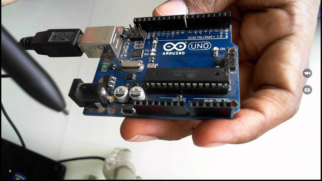
Beginning with Internet of Things IoT for Developers
171.5K
Arduino programming uses C-based sketches written in a simplified version of C. The Arduino IDE provides tools for writing, compiling, and uploading code to the board. The IDE includes a Serial Monitor for viewing output. Arduino programs have only two main constructs: setup() (runs once at startup) and loop() (runs continuously). Built-in functions include pinMode() for configuring pins as input or output, digitalWrite() for writing values to digital pins, and delay() for introducing time delays in milliseconds. Libraries are pre-written code that simplifies working with sensors and components, handling complex communication protocols and data interpretation.
Click to watch →

Basic concept of Arduino in Hindi | Arduino tutorials for beginners part #1
1.4M
Arduino IDE is free software available for all operating systems (Windows, Mac, Linux). Download from Arduino website by searching 'Arduino IDE' and clicking the first official option. After installation, the desktop icon launches the IDE containing: File menu (New, Open, Save), Examples menu with pre-written code templates (LED blinking, LCD interfacing, sensors), Sketch menu with Include Library for sensor commands, and Tools menu for board and port selection. For successful programming, select the correct board (Uno, Mega, Nano, Mini) and the connected serial port (e.g., COM3). The Upload button transfers programs to Arduino, enabling control of connected components like the built-in LED on pin 13.
Click to watch →
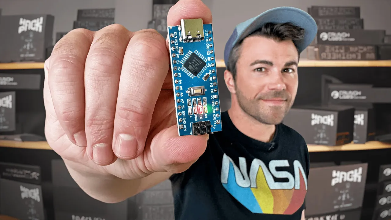
Arduino 101- Crash Course w/ Mark Rober
1.8M
To program an Arduino, you first download the free Arduino Integrated Development Environment (IDE) software from arduino.cc. After installing the software, you connect your Arduino board to your computer via USB. The IDE allows you to select the correct port for your specific Arduino model. Once connected, you can write, compile, and upload code to the microcontroller. Each version of code uploaded to an Arduino is called a 'sketch.' The Arduino IDE provides examples and templates to help beginners get started with programming.
Click to watch →
Deep Dive
Understanding the working principles of hobby servo motors, including signal, VCC, and GND connections.

1TE663/723 Lab 7 - recording 2020-12-02
389
Hobby servo motors are radio-controlled devices with three wires: brown (ground), red (5V power), and orange (control signal). Internally, they contain a DC motor, potentiometer for position sensing, gearbox, and a microcontroller-based feedback system. The potentiometer measures the actual position, while the controller compares it to commanded values from incoming PWM pulses. This closed-loop system ensures the motor reaches and maintains the desired position. The motor can rotate approximately 180 degrees (some models up to 270 degrees) and requires continuous 5V power for operation.
Click to watch →

Formation en électronique - Arduino - Cours 9 - Les moteurs | Sylvain Joannette Consultant
511
A servo motor is a rotary actuator capable of precise 180-degree positioning with built-in feedback. It requires three connections: Vcc (red), GND (brown), and signal (orange/yellow). The signal wire connects to a digital pin (e.g., pin 9), while Vcc connects to 5V and GND to ground. A potentiometer controls the position by providing an analog input (0-1023) that maps to the servo's 0-180 degree range. Proper wiring involves connecting the potentiometer's middle pin to an analog pin (A0), one outer pin to 5V, and the other to ground.
Click to watch →

Servos - working principle and homemade types
353.4K
A servo motor is a closed-loop control system that uses pulse-width modulation (PWM) signals to achieve precise angular positioning, where the control circuit converts the PWM signal into a DC voltage through low-pass filtering, compares it with feedback from a potentiometer sensor, and drives an H-bridge to rotate the motor until the actual position matches the commanded position; homemade servos can be created by modifying standard RC servos by removing hard stops and the potentiometer linkage, or by building custom circuits using RC filters, comparators, and H-bridges to convert conventional DC motors into controllable servos with adjustable speed and torque characteristics.
Click to watch →

Acionando o eixo Z com um Servo Motor
55.1K
This section provides detailed instructions for wiring a servo motor to an Arduino. A servo motor has three wires: ground (GND, typically brown or black), power (VCC, typically red), and signal (typically orange or yellow). The ground wire connects to Arduino's GND pin, the power wire connects to 5V (not 3.3V, as servos require 5V), and the signal wire connects to the Z+ pin on the CNC Shield, which corresponds to Arduino pin 11 (the PWM spindle control pin). The presenter recommends researching servo motor operation before attempting this connection, and suggests that beginners should stick with stepper motors for simpler implementations. Larger servos may require a driver amplifier instead of direct Arduino connection.
Click to watch →

CONTROLE SUAVE DE SERVO MOTORES | Curso de Arduino #018
44.8K
A servo motor has three wires: signal (orange, white, or yellow), 5V power (red), and ground (black). The signal wire connects to a microcontroller input. The signal is a TTL-level digital signal (5V) that controls an internal driver stage. The servo contains an internal motor connected to a gear reduction system.
Click to watch →
Deep Dive
Fundamental concepts of Pulse Width Modulation (PWM) and how duty cycles translate into physical servo arm positions.

What Is Dshot MultiShot OneShot and PWM | ESC MOTOR PROTOCOLS - PART 1
110.6K
PWM is a method where electrical high voltage pulses vary from 0% to 100% duty cycle. In PWM, the width of the electrical pulse determines the encoded information. In the RC hobby, PWM pulses range from 1,000 to 2,000 microseconds. The pulse is never at 0% duty cycle because servos require the high voltage pulse to receive energy for holding position. If duty cycle drops too low, servos lose authority to maintain their position. The pulse width directly corresponds to the throttle value being communicated.
Click to watch →

فكرة مشروع 1 : روبوت يحاكي حركة الذراع
107.3K
PWM (Pulse Width Modulation) is a square wave signal used to control servo motor angles. The duty cycle of the PWM signal determines the angle of the servo motor. As the duty cycle increases, the servo angle increases, and as the duty cycle decreases, the servo angle decreases. The frequency and duty cycle range of the PWM signal are specified in the servo motor's datasheet. The PWM signal is generated by a microcontroller such as Arduino, PIC, or Raspberry Pi, which can output PWM signals to control the servo motors.
Click to watch →

Que sabes del PWM?, principios electromecánica 1️⃣ | duty cycle | señal pwm automotriz
31.3K
PWM (Pulse Width Modulation) converts analog signals to digital signals that electronic control units can process. It uses rapid on/off switching to create a square wave signal. When the switch is closed, the load receives full voltage (12V); when open, it receives zero voltage. The period is the time to complete one full cycle. Duty cycle is the percentage of time the signal is 'on' during one period. A 50% duty cycle means the signal is on for half the period and off for the other half. This determines the average voltage delivered to the load. The average voltage equals the duty cycle percentage multiplied by the supply voltage. For example, a 50% duty cycle with 12V supply produces 6V average. This is analogous to filling a bucket with water: opening a tap for half the time collects half the water.
Click to watch →

How to Create PWM in Verilog on FPGA? | Xilinx FPGA Programming Tutorials
50.7K
PWM is a digital technique for achieving analog results by creating square waves with variable pulse widths. The duty cycle represents the percentage of time a pulse remains high during one complete cycle—for example, a 20% duty cycle means the pulse is high for 20% of the time and low for 80%. Implementing PWM requires four key components: a counter to track position in the cycle, a clock signal for synchronization, an output signal to drive loads, and a comparator to determine when to switch states. The counter increments on each clock cycle and resets when reaching a maximum value (e.g., 100). When the counter value is below a threshold (e.g., 20), the output is high; when it exceeds or equals the threshold, the output goes low. At high frequencies, rapid switching creates the illusion of constant brightness, where higher duty cycles produce brighter apparent output.
Click to watch →
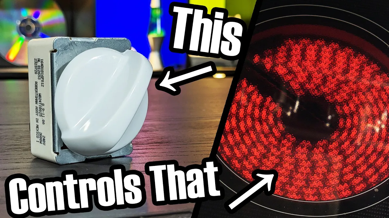
Simmerstats: The genius old tech that controls your stovetop
2.2M
This section explains duty cycle control as a method of achieving lower average power output by cycling a load on and off repeatedly. For example, a 1,200W burner at 50% duty cycle delivers 600W average power. The video distinguishes this from pulse width modulation (PWM), noting that while similar in effect, PWM serves broader signaling purposes (like controlling servo motors) whereas duty cycle control focuses solely on power delivery. The simmerstat represents a 100-year-old implementation of duty cycle control using purely mechanical means, contrasting with modern electronic implementations.
Click to watch →
Deep Dive
An introduction to the I2C communication protocol, specifically master-slave relationships, device addressing, and the SDA/SCL lines.

Шина I2C.
15.1K
The I2C (Inter-Integrated Circuit) bus is a two-wire serial communication protocol using SDA (Serial Data) and SCL (Serial Clock) lines, where one device acts as Master and others as Slaves; communication begins with a START condition (SDA transitions from high to low while SCL is high), followed by a 7-bit device address and a read/write bit, with each byte acknowledged by the receiving device through pulling the SDA line low during the clock pulse, and ends with a STOP condition (SDA transitions from low to high while SCL is high).
Click to watch →

What Is VREG, LDO, VSP, VSN, PWM, MIPI, I2C, SDA, SCL ? Mobile Repairing
117.7K
I2C uses two lines: SDA (Serial Data) and SCL (Serial Clock). The CPU acts as master, sending commands to slave ICs. Each slave has a unique address (code). When the CPU sends a command, only the matching address responds and performs the action. Pull-up resistors (2.2K ohms) connect SDA and SCL to 1.8V, maintaining signal strength over distance. This allows one CPU to efficiently control multiple ICs through shared communication lines.
Click to watch →

Лекция 308. Шина I2C
115.5K
The I2C (Inter-Integrated Circuit) bus is a two-wire serial communication protocol developed by Philips in the 1980s for connecting integrated circuit devices, using SDA (Serial Data) and SCL (Serial Clock) lines with a Master-Slave architecture where the Master generates clock signals and initiates communication, supporting hot-plugging of devices and capable of connecting multiple devices with 7-bit addressing (up to 100 devices) at speeds up to 100 kbps, with data transmission occurring only when SCL is low and using Start/Stop conditions for communication framing.
Click to watch →

I2C Communication Protocol and Arduino Implementation Tutorial
1.6M
I2C (Inter-Integrated Circuit) is a serial communication protocol that enables multiple devices to communicate over just two wires (SCL for clock and SDA for data), using a master-slave architecture where the master initiates communication by sending a device address followed by register addresses and data bytes, with each 8-bit sequence followed by an acknowledge bit from the slave device; practical implementation with Arduino involves using the Wire library to send device addresses and register addresses, then reading the returned data bytes.
Click to watch →
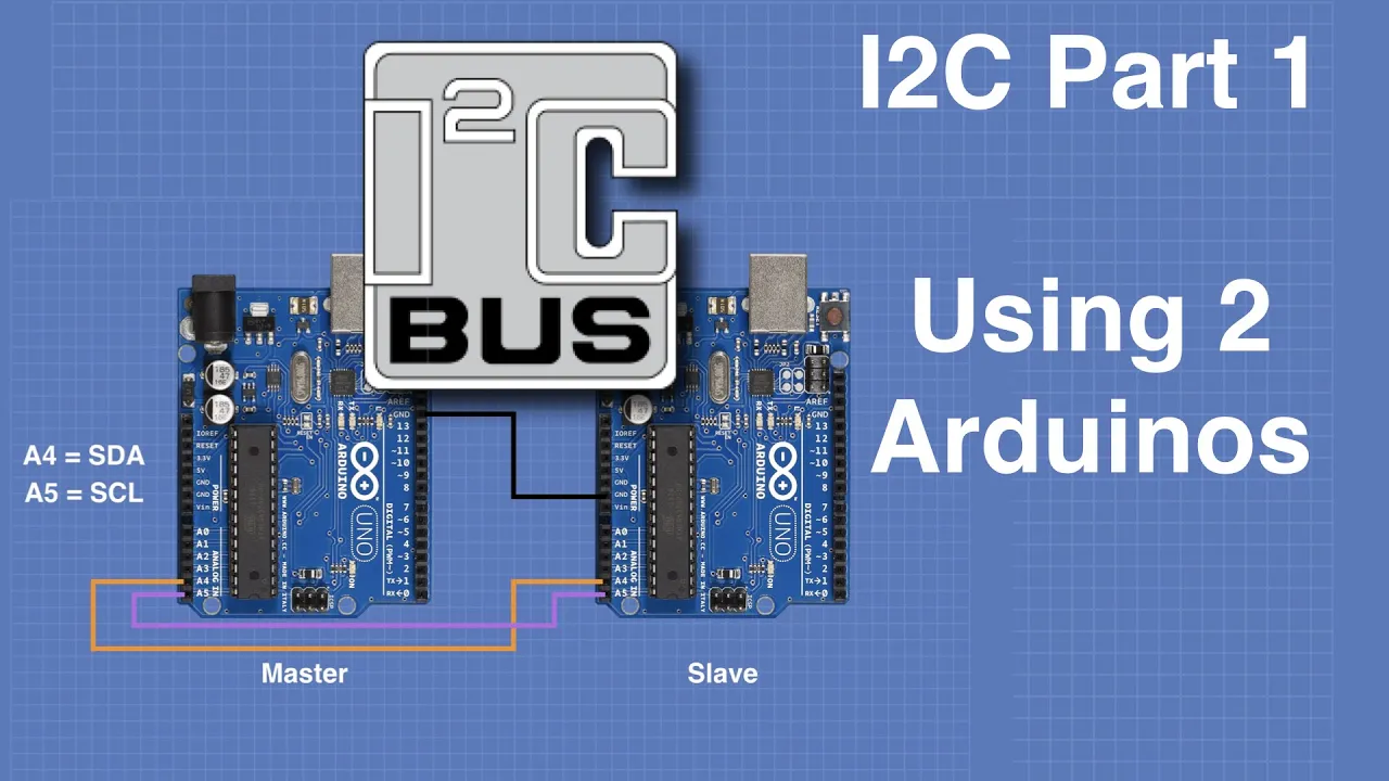
I2C Part 1 - Using 2 Arduinos
465.6K
I2C (Inter-Integrated Circuit) is a two-wire serial communication protocol originally developed by Philips in 1982 for television circuits, now widely used for connecting microcontrollers, sensors, and displays. It operates on a master-slave architecture where the master device generates the clock signal and initiates all communications, while slaves respond to the master's commands. The protocol uses only two wires: SDA (Serial Data Line) and SCL (Serial Clock Line), with pull-up resistors ensuring proper signal integrity. Each slave device has a unique 7-bit address, allowing up to 128 devices on a single bus. Using the Arduino Wire library, you can easily implement I2C communication between two Arduinos by connecting their grounds together and tying their SDA and SCL lines together. The master can send data to the slave using Wire.beginTransmission() and Wire.write(), while the slave receives data through the onReceive() function and can respond using Wire.write() when the master requests data.
Click to watch →
Deep Dive
Basic knowledge of electrical power distribution, specifically why multiple high-draw inductive loads (servos) require an external power source separate from the microcontroller.

Tutorial: PWM and Servos with Micropython for ESP32 and ESP8266
4K
This section explains the power requirements of servo motors and why external power supplies are necessary. Servo motors draw varying current: idle state ~10mA, normal movement 100-250mA, stalled conditions up to 360mA. Small servos like the SG90 may work directly from the microcontroller's 5V pin, but larger servos require external power supplies to prevent microcontroller damage. The section emphasizes that the microcontroller should only handle control signals while dedicated power supplies provide the necessary current for motor operation.
Click to watch →

Arduino Servo Motor Control, Arduino, ESP32, ESP8266...
163
Servo motors require external power supply because they consume significant current (200-300mA per servo). A single SG90 can be powered directly from a microcontroller's 5V output, but connecting multiple servos exceeds the microcontroller's current capacity. An external power source should supply both the microcontroller and the servos, with the power supply capacity determined by the number of servos operating simultaneously.
Click to watch →

Robotic Arm (Seven) Assembly: 3-DOF 3D Printed Project
288
When using multiple servos (such as four SG90 servos), an external power supply is required because the Arduino's 5V pin cannot handle the combined current draw. To create an external power supply, strip one end of a USB cable and connect the red wire (positive 5V) and black wire (ground) to a breadboard. Use a USB-A to USB-C converter connected to a quality 5V 3A adapter. Always ensure exposed wires do not touch each other to prevent short circuits.
Click to watch →

DIY Motorized Pan & Tilt Camera Mounting System - Part 1
33.9K
Servos require separate power from the microcontroller board because they draw significantly more current than the Raspberry Pi or Arduino can safely provide. The servo driver board has dedicated power connections (labeled voltage positive) that must be connected to an external power source (such as a 6V battery pack), while the ground connection is shared between the controller and servos. This separation prevents power fluctuations from affecting the microcontroller's operation.
Click to watch →
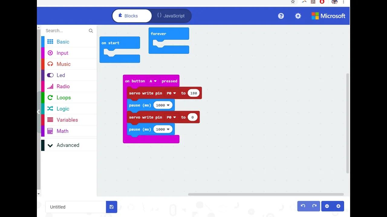
Control high power motors with the micro:bit!
2.1K
Large servo motors require more power than a microcontroller's built-in power supply can provide. An external power supply (such as batteries or a wall adapter) must be used to power the servo motor separately from the microcontroller. The microcontroller only needs to provide the signal to control the motor, not the power.
Click to watch →
Prerequisite Knowledge
- Concept 01Basic proficiency in Arduino programming and using the Arduino IDE to write, compile, and upload sketches.
- Concept 02Understanding the working principles of hobby servo motors, including signal, VCC, and GND connections.
- Concept 03Fundamental concepts of Pulse Width Modulation (PWM) and how duty cycles translate into physical servo arm positions.
- Concept 04An introduction to the I2C communication protocol, specifically master-slave relationships, device addressing, and the SDA/SCL lines.
- Concept 05Basic knowledge of electrical power distribution, specifically why multiple high-draw inductive loads (servos) require an external power source separate from the microcontroller.
Subsequent Learning
- Step 01Designing and programming complex multi-joint robotic structures, such as quadruped walkers, hexapods, or multi-axis robotic arms.
- Step 02Implementing daisy-chaining techniques with multiple PCA9685 modules to scale control up to hundreds of servos using the same I2C bus.
- Step 03Studying and applying Inverse Kinematics (IK) to calculate precise servo angles for coordinated, coordinate-based mechanical movements.
- Step 04Developing non-blocking timing routines (using timers or millis()) to execute smooth, simultaneous, and speed-controlled multi-servo movements.
- Step 05Integrating real-time sensor feedback (such as IMUs or distance sensors) to build closed-loop, self-correcting robotic systems.
Opening Act
Vocal Phase
Build-Up
Peak Section
Instrumental Break
Vocal Return
Final Stretch
Closing Note
Opening Act
0:28Playing Section
- 1
Performance begins with musical introduction.
- 2
Audience responds with applause early on.
Smart Serial Servos vs. Analog PWM Control
While the Arduino and PCA9685 combination is a popular, budget-friendly way to generate 16 PWM signals, it has significant limitations for advanced robotics. Standard PWM servos are 'dumb' actuators; they provide no feedback regarding their actual position, internal temperature, or load. Furthermore, wiring 16 individual three-wire servos to a central PCA9685 board creates a complex 'cable spaghetti' and major power-distribution bottlenecks. An alternative, industry-standard approach is utilizing Smart Serial Servos (such as Dynamixel or bus servos). Instead of dedicated PWM channels, these servos are daisy-chained together on a single shared serial bus, drastically reducing wiring complexity to just one cable run. Crucially, they support bidirectional communication, allowing the controller to read real-time diagnostics like torque, position, and temperature. This telemetry is essential for closed-loop control, active force-feedback, and safety shutdowns in sophisticated robotic systems, presenting a much more scalable architecture than traditional PWM controllers.
Deep Dive
Designing and programming complex multi-joint robotic structures, such as quadruped walkers, hexapods, or multi-axis robotic arms.

3.Robotics Mid Term Exam.
172
Complex multi-joint robots can be designed by decomposing them into simpler subsystems. A five-joint robot can be viewed as two Scarab-like robots sharing a common base (J3). The left subsystem uses joints J1, J2, J3 with J3 as the base, while the right subsystem uses joints J3, J4, J5 with J3 as the base. This decomposition allows the same kinematic functions (FK2, IK2) to be reused for both subsystems. The body (J3) is first lifted and moved sideways, creating new pivot points. Then each leg is lifted and placed at new positions, creating a coordinated walking motion. This demonstrates how complex locomotion can be achieved by combining simpler kinematic patterns.
Click to watch →

Robotics | Science vs Terrorism 1/4 | True Story Documentary Channel
4.3K
Quadruped robots are complicated to design and control because they have many degrees of freedom - 12 actuator systems that need to accommodate weight and provide sufficient torque for the robot to stand and run at sufficient speed. Software is used to simplify complex mechanical problems to achieve precise control for balance and coordination of different legs.
Click to watch →

How to Design a DIY Quadruped Robot
94.9K
Each leg of a quadruped robot typically uses three servo motors controlling three joints: the hip joint (connecting to the torso), the femur (upper leg), and the tibia (lower leg/knee). Placing the knee servo motor above the knee joint keeps leg weight closer to the torso. This three-joint configuration allows the foot to move in all three spatial dimensions (pitch, yaw, roll), enabling complex movements like climbing and navigating obstacles.
Click to watch →
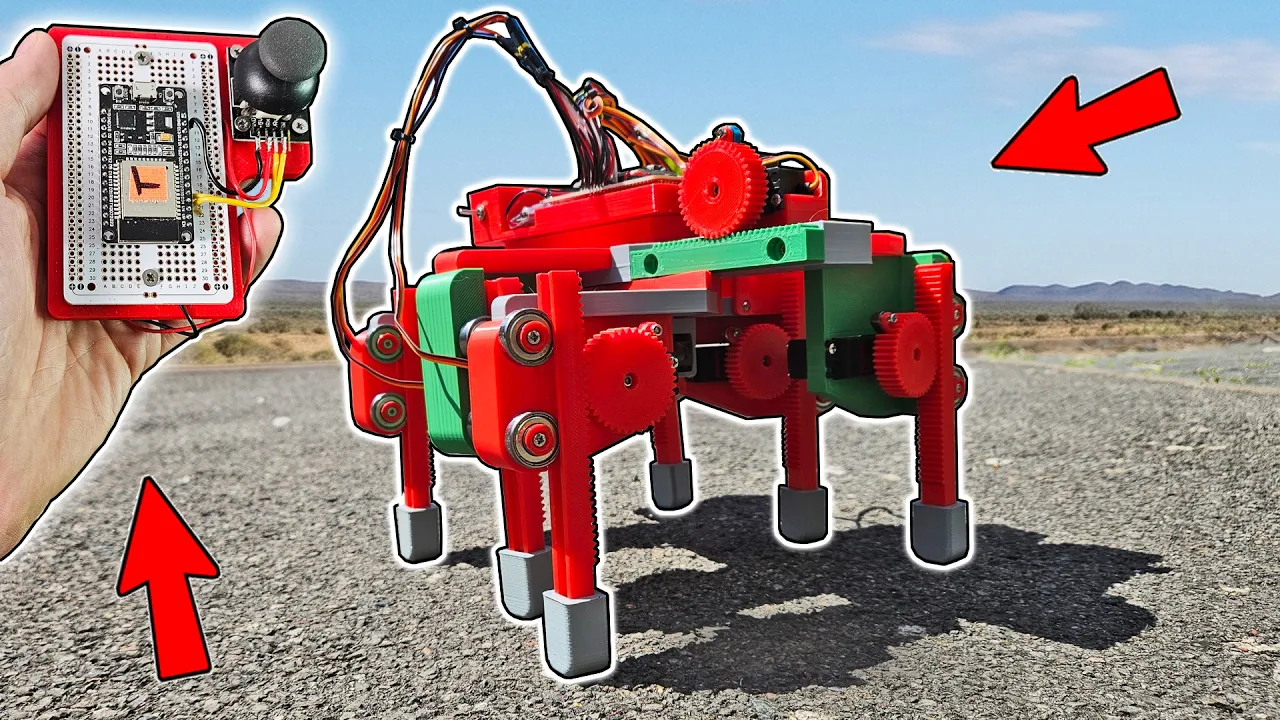
Anti-Inverse-Kinematics Hexapod
136
This video demonstrates a hexapod robot design that uses rack and pinion mechanisms for linear leg movement, eliminating the need for complex inverse kinematics calculations. The robot features six legs with linear actuators (servos driving racks) that move in straight lines, allowing the robot to walk, turn on the spot, and navigate terrain while maintaining tripod stability with at least three legs on the ground at all times. The design uses ESP32 microcontrollers with ESP Now for wireless remote control, and all CAD files are published in STEP format for open-source modification.
Click to watch →

HGSRW Cybuster/Cybaster Review
1.1K
Complex robot models require multiple joint types working together to achieve realistic movement. The Side Buster combines ball joints (for multi-directional rotation), upward hinges (for vertical movement), forward hinges (for linear movement), and universal joints (for complex multi-axis movement) across its body. The hip area uses universal joints with peg-based connections, providing decent range of motion in multiple directions. This layered approach to joint design demonstrates how model builders balance complexity against practicality, using different joint types strategically to maximize mobility while keeping construction feasible.
Click to watch →
Deep Dive
Implementing daisy-chaining techniques with multiple PCA9685 modules to scale control up to hundreds of servos using the same I2C bus.
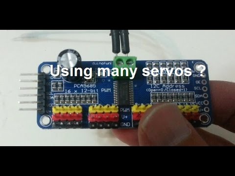
A simple method to control upto almost 1000 servos
68.6K
The PCA9685 is a 16-channel 12-bit PWM driver that enables control of up to nearly 1000 servos by chaining multiple modules together using the I2C protocol, which requires only two pins for communication and simplifies servo control by eliminating the need for continuous command refreshing.
Click to watch →

#128 Arduino for Model Railways - Switches Part 1 Momentary Switches and Stud & Probe Servo control
1.3K
The PCA9685 is a servo driver board that allows control of multiple servos using I2C communication, freeing up Arduino pins for other uses. Each board can control up to 16 servos. The servo step size determines how smoothly servos move - smaller values (like 3) provide smoother movement but consume more processing time. Multiple PCA9685 boards can be daisy-chained together and controlled from the same two Arduino pins. The servo set movement function must include parameters for the board address, port number, destination angle, and duration.
Click to watch →
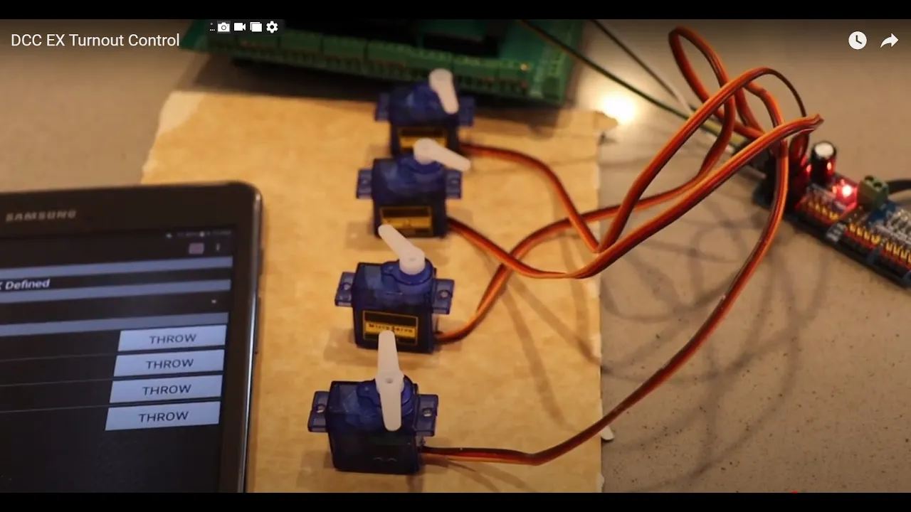
DCC EX Turnout Control OLD VERSION - SEE UPDATED VERSION
13.1K
The PCA 9685 board requires separate power supplies: the 5V input drives the chip itself while a separate 2A power supply drives the servos. The board features 16 servo headers and daisy chain connections for multiple boards. When connecting multiple boards, the OE pin can be left disconnected, and the V+ power carries through the chain. Each board requires a unique I2C address (default 0x40, changeable by soldering on address pads) to communicate with the Arduino.
Click to watch →
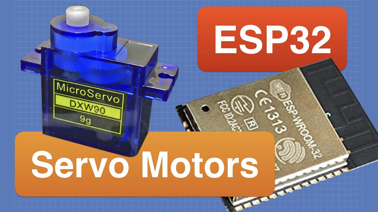
Using Servo Motors with ESP32
265.7K
The PCA9685 is an I2C module with 16 PWM outputs that can drive up to 16 servo motors. It uses pull-up resistors (approximately 2.4kΩ for 3.3V I2C). Each PWM cycle is divided into 496 sections called ticks, allowing precise pulse width control by specifying start and end points. Multiple modules can be cascaded using different I2C addresses, theoretically supporting up to 62 modules (992 servos total). The Adafruit PWM Servo Driver library abstracts the tick calculations, making it easier to work with. The code example demonstrates controlling two servos by mapping positions to tick values and using the setPWM method.
Click to watch →
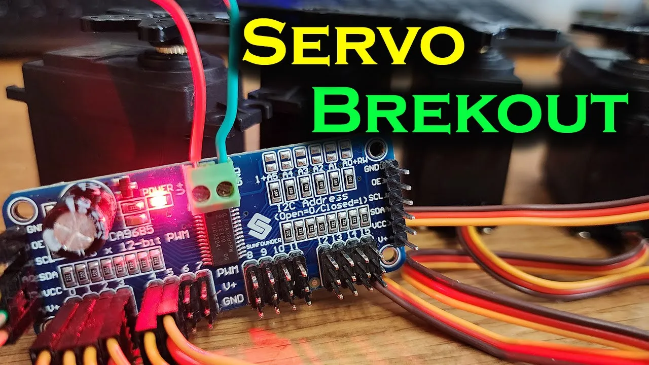
Mastering Servo Control: PCA9685 PWM Driver with Arduino Tutorial and Demo
70.3K
The PCA9685 is a 16-channel PWM driver that enables precise control of multiple servo motors using I2C communication, freeing up the Arduino microcontroller to perform other tasks; it can control up to 16 servos with a single board or chain multiple boards together for 992 total outputs, with each board having a unique I2C address configurable via solder jumpers, and requires external 5V power for the servos while the VCC pin only powers the driver chip.
Click to watch →
Deep Dive
Studying and applying Inverse Kinematics (IK) to calculate precise servo angles for coordinated, coordinate-based mechanical movements.
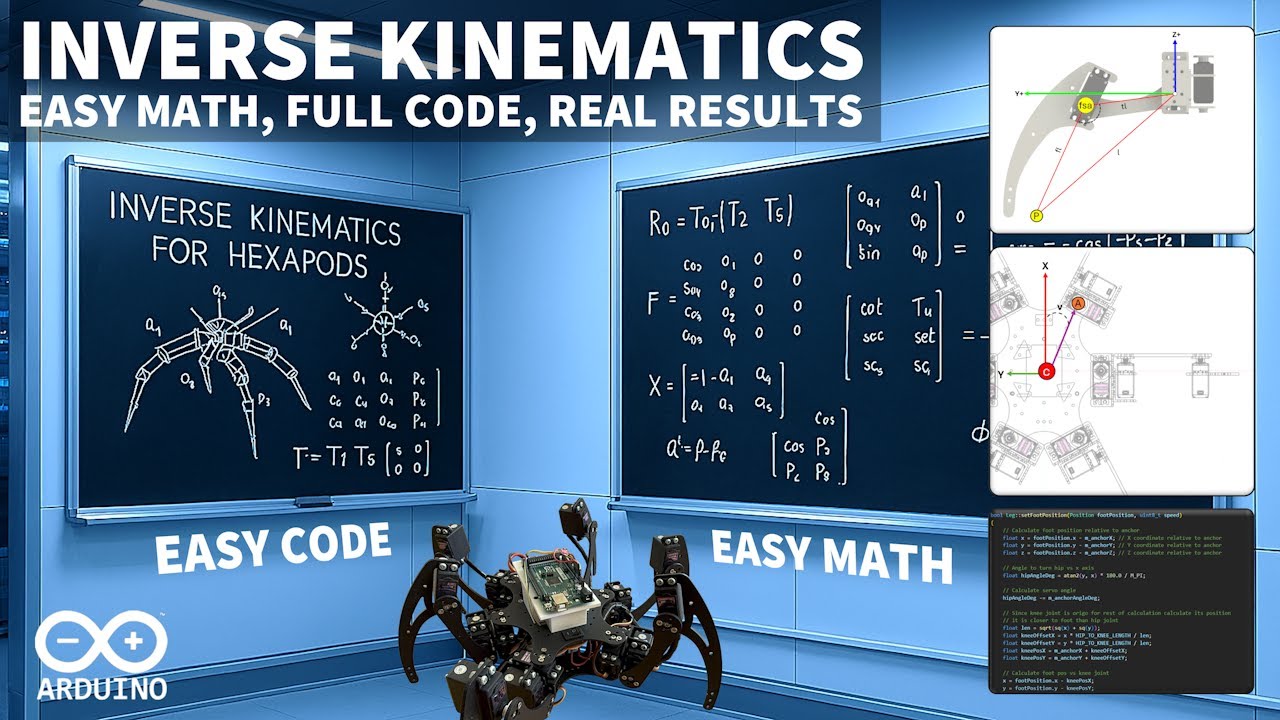
Master Inverse Kinematics for Arduino Robots – Easy Math, Full Code, Real Results
105.5K
Robot kinematics studies how robots move using joints (rotating parts like hips, knees, feet) and links (rigid connecting parts like thighs and feet). Forward kinematics tells each servo where to move, resulting in predictable foot positions but becoming impractical for complex movements. Inverse kinematics reverses this: specify desired foot position, then calculate required joint angles. A right-handed coordinate system is standard for robotics, with x-axis forward, z-axis up, and y-axis left when viewed from behind. Angles can be calculated in radians (Arduino default, full rotation = 2π) or converted to degrees for easier visualization. Three mathematical operations suffice for inverse kinematics: calculating angles from single lines using arctan, solving right triangles with known sides, and calculating any triangle's angles when all three sides are known.
Click to watch →

FABRIK (Inverse kinematics)
76.6K
Inverse kinematics (IK) is the reverse problem of forward kinematics. Given a starting position, fixed segment lengths, and a desired end effector position (goal), IK determines what joint angles are needed so that the chain of rigid segments reaches exactly that goal position. Unlike forward kinematics which calculates position from angles, IK calculates angles from position. This has applications in animation (like character limb movement), robotics, and game development for creating realistic motion.
Click to watch →

Meet Caroline: Testing ways to build a cheap Robot Arm (for science!)
124.3K
Inverse kinematics (IK) enables a robot arm to move its end effector to specific positions in space while controlling orientation. Unlike forward kinematics which calculates position from joint angles, IK solves for the necessary joint angles to achieve a desired end position. This allows for sophisticated movements like tracked slider moves (keeping focus point fixed while moving head) or tripod-style pan and tilt motions, with complete control over how motion is generated through custom IK solvers.
Click to watch →

All Constraints Explained with Example | Tracking Constraints | Blender 2.8 | Free Project File
95.1K
The IK constraint is essential for character rigging and mechanical rigging. To set up IK: (1) Create bones for each object to be controlled, (2) Parent objects to their respective bones using Ctrl+P, (3) Add an IK constraint to the armature, (4) Set the target bone, (5) Configure settings like pole target, chain length, and self-extender. The constraint allows end effector movement while automatically calculating intermediate joint positions.
Click to watch →

Cinema 4D Tutorial - Intro to Mechanical IK Rigging
180.8K
Forward Kinematics (FK) is the simplest to set up but most laborious for animation, requiring manual rotation of each joint in a hierarchy. Inverse Kinematics (IK) works inversely - you only need to animate one object (the end effector), and it automatically animates everything above it in the chain. This makes IK much more efficient for complex rigs with multiple joints.
Click to watch →
Deep Dive
Developing non-blocking timing routines (using timers or millis()) to execute smooth, simultaneous, and speed-controlled multi-servo movements.
10 Multitasking in Arduino using millis | Servo Motor and 7-segment Display | Embedded Systems
59.3K
Arduino lacks an operating system, so multitasking requires avoiding the delay() function, which completely halts the processor. The millis() function returns milliseconds since program start, enabling non-blocking timing. By storing start times and checking elapsed intervals, multiple independent operations can run concurrently. Servo motors use PWM signals where pulse width determines shaft position: 1.5ms = 90°, ~1ms = 0°, ~2ms = 180°. The Servo.h library simplifies control with attach(pin) and write(angle). Three wires connect servos: power (red to 5V), ground (black/brown to GND), and signal (yellow/white/orange to any digital pin). Integrating servos with displays using millis() requires separate timing variables for each component, enabling simultaneous independent operation.
Click to watch →
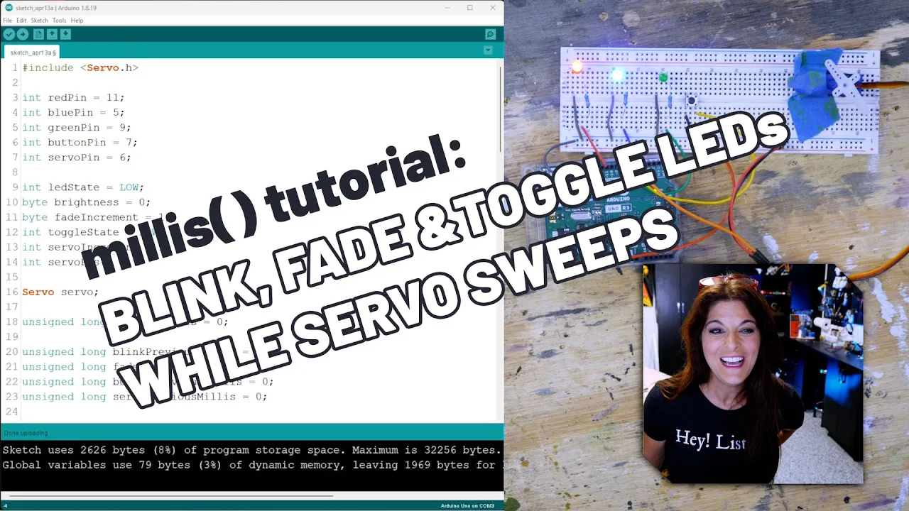
How to Use Millis to Master Arduino Multi-tasking
87.7K
The millis() function enables Arduino multitasking by tracking elapsed time since startup (counting up to ~49 days as an unsigned long), allowing multiple timed operations like blinking LEDs, fading LEDs, button toggles, and servo sweeps to run concurrently without blocking each other, unlike the delay() function which pauses the entire program.
Click to watch →
⏰ Прерывания в Arduino (AVR) по таймеру и многозадачность. Arduino для начинающих
122.5K
To create non-blocking delays, use the Arduino millis() function which returns milliseconds since board startup. Store the current time when starting a task, then check if the difference between current time and stored time exceeds the desired interval. The millis() variable uses an unsigned long (32-bit), holding values from 0 to 4 billion milliseconds (about 46 days) before overflowing. For longer timing, use a separate variable counting seconds, which would overflow after approximately 136 years. To enable/disable timers, use a boolean flag variable. In the interrupt handler, only increment the timer variable if the flag is true. When reading timer variables in the main loop, first disable interrupts (cli()), read the variable, then re-enable interrupts (sei()) to prevent reading corrupted data.
Click to watch →
Explorando o Arduino - Aula 2 - Multitarefas
48.3K
To implement non-blocking timing: (1) Declare a static unsigned long variable to store the initial timing value, (2) Call millis() to get the current time, (3) Store this value in the variable, (4) In the loop, compare millis() minus the stored value against the desired interval. If the difference equals the interval, execute the action and update the stored value.
Click to watch →

The 'knife-wielding tentacle' Build. Full version
147K
This video demonstrates how to control a servo motor using Arduino with the 'Blink Without Delay' program, where the Arduino controls a servo motor through pin 13 (the LED pin) via a Proto bit interface, and the program's interval can be adjusted (to 500ms in this case) to control the speed of the mechanical movement.
Click to watch →
Deep Dive
Integrating real-time sensor feedback (such as IMUs or distance sensors) to build closed-loop, self-correcting robotic systems.

Behind the Bot 14361 | CPHS ROBOLOBOS GREEN | POWERPLAY Robot
2.5K
Modern robotics relies on integrated sensor networks for autonomous operation and real-time adjustment. Color sensor arrays enable consistent line following and object detection. Dead wheel odometry combined with IMU systems provides accurate positioning data. Distance sensors on robotic arms enable automatic tilt correction and collision avoidance. These systems demonstrate how multiple sensor types working together create adaptive robots capable of self-correction during operation, representing the core principle of feedback control in autonomous systems.
Click to watch →

Lec-1 Introduction to control problem
566.8K
A closed-loop feedback control system structure includes a sensor that measures the controlled variable and feeds this information back to the controller. The controller compares the actual controlled variable (from the sensor) with the command signal to generate an error signal. This error signal is then used to generate a suitable control signal that manipulates the plant input. This creates an error self-nulling process where the controller action reduces the error to zero. The system is called closed-loop because the loop is closed through the feedback path, allowing the controller to respond to both command signals and disturbances indirectly through the controlled variable measurement.
Click to watch →

2020 RoboSoft: Closing the Loop with Liquid-Metal Sensing Skin for Autonomous Soft Robot Gripping
215
This video presents a sensor-based finite state machine control system for autonomous soft robot gripping, where a soft gripper equipped with liquid-metal sensing skin containing time-of-flight distance sensors, pressure sensors, and an inertial measurement unit enables closed-loop control for scanning, grasping, and sorting tasks. The system demonstrates that simple finite state machine control strategies can successfully achieve autonomous object manipulation in soft robots with low control authority by using multimodal sensor feedback to detect object presence, confirm grasp success, and respond to external perturbations.
Click to watch →
Flying Phone Scam Exposed (so I built a REAL one)
70.7M
Closed-loop feedback control systems continuously gather information about a system's state and make real-time adjustments to maintain stability. In balancing, human eyes detect tilt, the brain processes this information, and hands respond by making compensating movements. This same principle applies to thermostats (which check temperature and turn heating on/off), dartboards (which adjust position 200 times per second), and all flying machines that need to stay aloft. Without continuous feedback, systems cannot automatically correct for disturbances.
Click to watch →
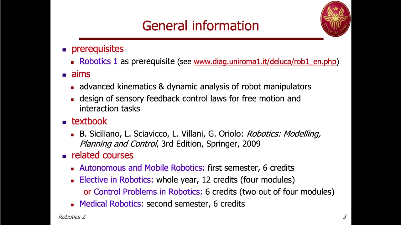
Robotics 2 - Prof. De Luca Lecture 01 part 1 (24 Feb 2020)
7.9K
Feedback control compensates for errors by reacting to measured quantities. Different sensors are used: visual sensors on end effectors for vision-based feedback, force sensors for contact tasks. The default minimum measurements include joint position encoders. Controllers are designed at the torque level, outputting torques actuators should produce to achieve desired behavior. This compensates for errors and handles uncertainties in the robot's physical properties.
Click to watch →
Opening Act
Vocal Phase
Build-Up
Peak Section
Instrumental Break
Vocal Return
Final Stretch
Closing Note
Opening Act
0:28- 1
Performance begins with musical introduction.
- 2
Audience responds with applause early on.
Smart Serial Servos vs. Analog PWM Control
While the Arduino and PCA9685 combination is a popular, budget-friendly way to generate 16 PWM signals, it has significant limitations for advanced robotics. Standard PWM servos are 'dumb' actuators; they provide no feedback regarding their actual position, internal temperature, or load. Furthermore, wiring 16 individual three-wire servos to a central PCA9685 board creates a complex 'cable spaghetti' and major power-distribution bottlenecks. An alternative, industry-standard approach is utilizing Smart Serial Servos (such as Dynamixel or bus servos). Instead of dedicated PWM channels, these servos are daisy-chained together on a single shared serial bus, drastically reducing wiring complexity to just one cable run. Crucially, they support bidirectional communication, allowing the controller to read real-time diagnostics like torque, position, and temperature. This telemetry is essential for closed-loop control, active force-feedback, and safety shutdowns in sophisticated robotic systems, presenting a much more scalable architecture than traditional PWM controllers.
Basic proficiency in Arduino programming and using the Arduino IDE to write, compile, and upload sketches.
Understanding the working principles of hobby servo motors, including signal, VCC, and GND connections.
Fundamental concepts of Pulse Width Modulation (PWM) and how duty cycles translate into physical servo arm positions.
An introduction to the I2C communication protocol, specifically master-slave relationships, device addressing, and the SDA/SCL lines.
Basic knowledge of electrical power distribution, specifically why multiple high-draw inductive loads (servos) require an external power source separate from the microcontroller.
Designing and programming complex multi-joint robotic structures, such as quadruped walkers, hexapods, or multi-axis robotic arms.
Implementing daisy-chaining techniques with multiple PCA9685 modules to scale control up to hundreds of servos using the same I2C bus.
Studying and applying Inverse Kinematics (IK) to calculate precise servo angles for coordinated, coordinate-based mechanical movements.
Developing non-blocking timing routines (using timers or millis()) to execute smooth, simultaneous, and speed-controlled multi-servo movements.
Integrating real-time sensor feedback (such as IMUs or distance sensors) to build closed-loop, self-correcting robotic systems.
178.1K views2.1Klikes4:15@sritu_hobbyOriginal Release: 2021-05-11
[Music] [Applause] [Music] do [Music] so [Music] so [Music] [Applause] [Music] [Music] so [Music] [Applause] [Music] [Music] [Applause] [Music] [Music] you
Up Next
22:12
V-22 Osprey Twin-Rotor Aircraft: Rotor Head Design and Testing
@TomStantonEngineering
4.3M views•2022-12-08

30:32
Ultrasonic Transducers: Resonant Frequency Measurement and Horn Design
@imajeenyus42
229.9K views•2017-02-22

54:16
Polymer Environmental Degradation: Mechanisms & Stabilization
@iit
1.8K views•2012-07-10

33:39
How a Student's Question Saved a NYC Skyscraper from Collapse
@veritasium
22.8M views•2025-04-26
Related Study Plans & Knowledge Roadmaps
Structured learning paths in Engineering
engineering
Building Acoustic Levitators: Physics & Arduino
01The Physics of Sound and Standing Waves
02Piezoelectric Transducers and H-Bridge Drivers
03Arduino Programming: Generating 40 kHz Signals
+ 2 more learning modules
14h5 modules
Explore Roadmap
engineering
Building Peltier Cloud Chambers: Particle Tracks
01Cosmic Rays & Cloud Chamber Physics
02Thermoelectric Cooling (TEC) Fundamentals
03Custom Liquid-Cooling Loop Design
+ 2 more learning modules
18h5 modules
Explore Roadmap
engineering
Yagi-Uda Antennas: Modeling, Build & VNA Test
01Introduction to RF and Antenna Fundamentals
02Yagi-Uda Antenna Design Principles
03Antenna Modeling and Simulation in 4NEC2
+ 2 more learning modules
18h5 modules
Explore Roadmap
engineering
ECG Monitor Design: Op-Amps, Filters & Noise
01Electronics & Breadboard Basics
02Op-Amps and Instrumentation Amplifiers
03Bioelectricity and ECG Fundamentals
+ 2 more learning modules
18h5 modules
Explore Roadmap