Stone arch bridges achieve remarkable durability by using a carefully shaped arch structure where stones are wider at the top and narrower at the bottom, which redirects applied forces outward along the curve of the arch into the supports rather than pushing downward, making the bridge more stable under load and allowing it to withstand floods for centuries without steel reinforcement.
Stone Arch Bridges: How Ancient Engineering Distributes Load and Survives Floods for Centuries
Added:Deep Dive
Understanding the difference between compressive and tensile forces, and how various materials behave under these stresses.
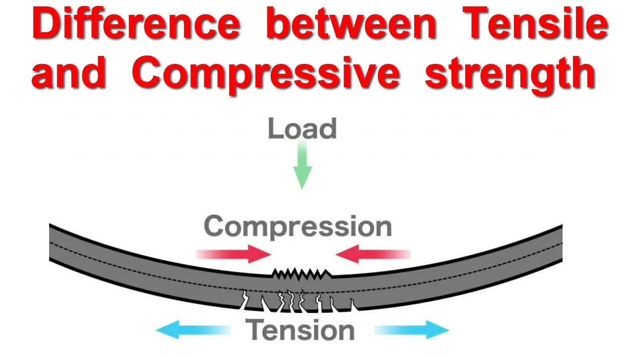
Difference between Tensile and Compressive Strength
54.5K
Tensile strength is the maximum resistance a material can develop when subjected to tensile (pulling) loads that tend to elongate the material, while compressive strength is the maximum resistance a material can develop when subjected to compressive (pushing) loads that tend to shorten or squeeze the material; both are calculated as the maximum load divided by the cross-sectional area, representing the material's maximum load-bearing capability before failure.
Click to watch →
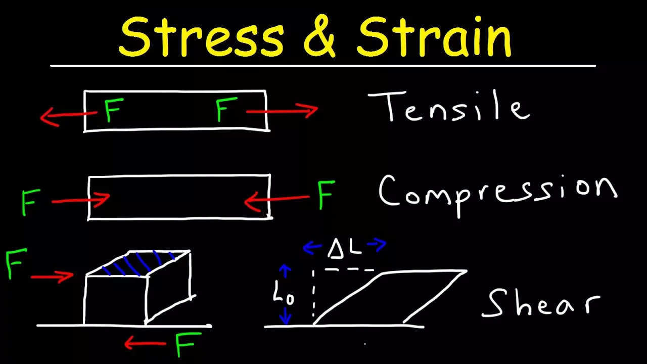
Tensile Stress & Strain, Compressive Stress & Shear Stress - Basic Introduction
837.7K
Stress is defined as force per unit area (F/A), while strain measures the fractional change in length (ΔL/L₀); tensile stress causes elongation with positive strain, compressive stress causes shortening with negative strain, and shear stress causes angular deformation; Young's modulus (E) relates tensile/compressive stress to strain through ΔL = (F × L₀)/(A × E), and shear modulus (G) relates shear stress to shear strain (Δx/h) through similar equations; materials have distinct ultimate strengths—for example, concrete has a maximum tensile strength of 2×10⁶ N/m² and compressive strength of 20×10⁶ N/m², making it much stronger under compression than tension.
Click to watch →

2026 THEORY | PHYSICS - පදාර්ථයේ යාන්ත්රික ගුණ Seminar
23.4K
Tensile stress and strain describe stretching behavior: tensile stress is force per unit area (σ = F/A), and tensile strain is fractional increase in length (ε = ΔL/L). Compressive stress and strain describe compression: compressive stress is force per unit area (σ = F/A), and compressive strain is fractional decrease in length (ε = ΔL/L). These quantities describe how materials respond to stretching and compressive forces. Understanding these concepts is essential for analyzing material behavior under different loading conditions.
Click to watch →
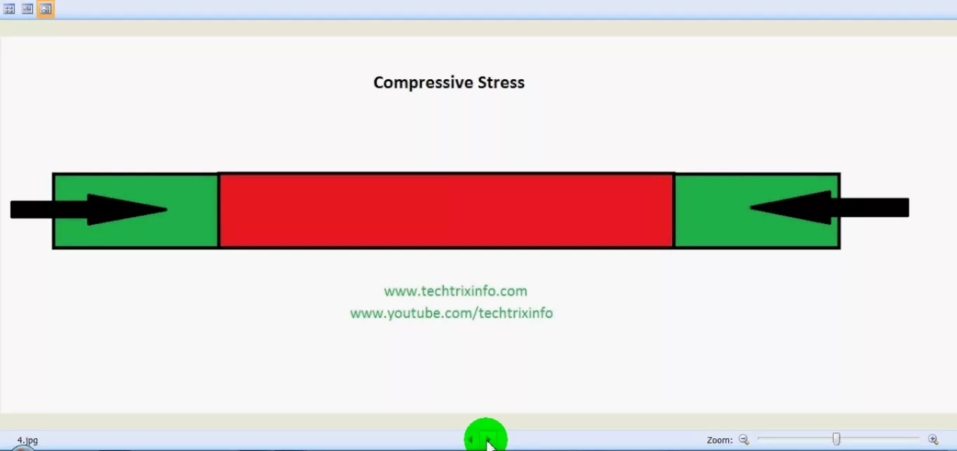
How stress, tensile stress, compressive stress works. ✔
64.3K
Stress is the internal resistance per unit area that a material develops when subjected to external forces, calculated as force divided by cross-sectional area; tensile stress occurs when equal and opposite pulling forces cause a material to lengthen, while compressive stress occurs when equal and opposite pushing forces cause a material to shorten.
Click to watch →

दिव्यास्त्र Series | Elasticity-01 | Elasticity for Airforce X Group & NDA, Navy, ICG | RS SIR
6.4K
Stress can be compressive (squeezing, reducing volume) or tensile (stretching, increasing volume). Compressive stress reduces the volume of a material, while tensile stress increases its volume. The instructor uses examples like gas compression and tire inflation to illustrate these concepts.
Click to watch →
Deep Dive
Basic principles of static equilibrium, where the sum of all forces and moments acting on a structure equals zero.

Lecture 2 | Unit 2 | Mechanics Of Structure | Equations of Static Equilibrium |Equation Of Condition
436
A body is in static equilibrium when the algebraic sum of all external forces equals zero and the algebraic sum of moments about any point equals zero. In 2D, this requires ΣFx = 0 and ΣFy = 0. In 3D, six equations are needed: ΣFx = 0, ΣFy = 0, ΣFz = 0, ΣMx = 0, ΣMy = 0, and ΣMz = 0. A particle is at rest in static equilibrium when forces are balanced and net torque is zero.
Click to watch →

2223 - MTESTA12 - Les 2
101
Static equilibrium requires that the sum of all forces in all directions equals zero, and the sum of all moments about any point equals zero. This applies to stationary structures that do not move. The fundamental principle is that for a structure to remain in equilibrium, all forces must balance out to zero, and all rotational tendencies must also balance out to zero.
Click to watch →

Kräfte- und Momentengleichgewicht - Fachwerke und statisches Gleichgewicht 7
155.3K
A system achieves equilibrium when forces and moments are balanced, preventing motion or rotation. For planar systems, three independent equilibrium conditions must be satisfied: ΣFx = 0, ΣFy = 0, and ΣM = 0. The force equilibrium requires that the vector sum of all forces equals zero, with separate conditions for each perpendicular direction. The moment equilibrium requires that the algebraic sum of all moments about any point equals zero. Support forces are conventionally drawn as positive values, while weight forces are negative. The reference point for moment calculations can be chosen strategically to simplify computations, typically at support locations to eliminate unknown reaction forces from the moment equation.
Click to watch →
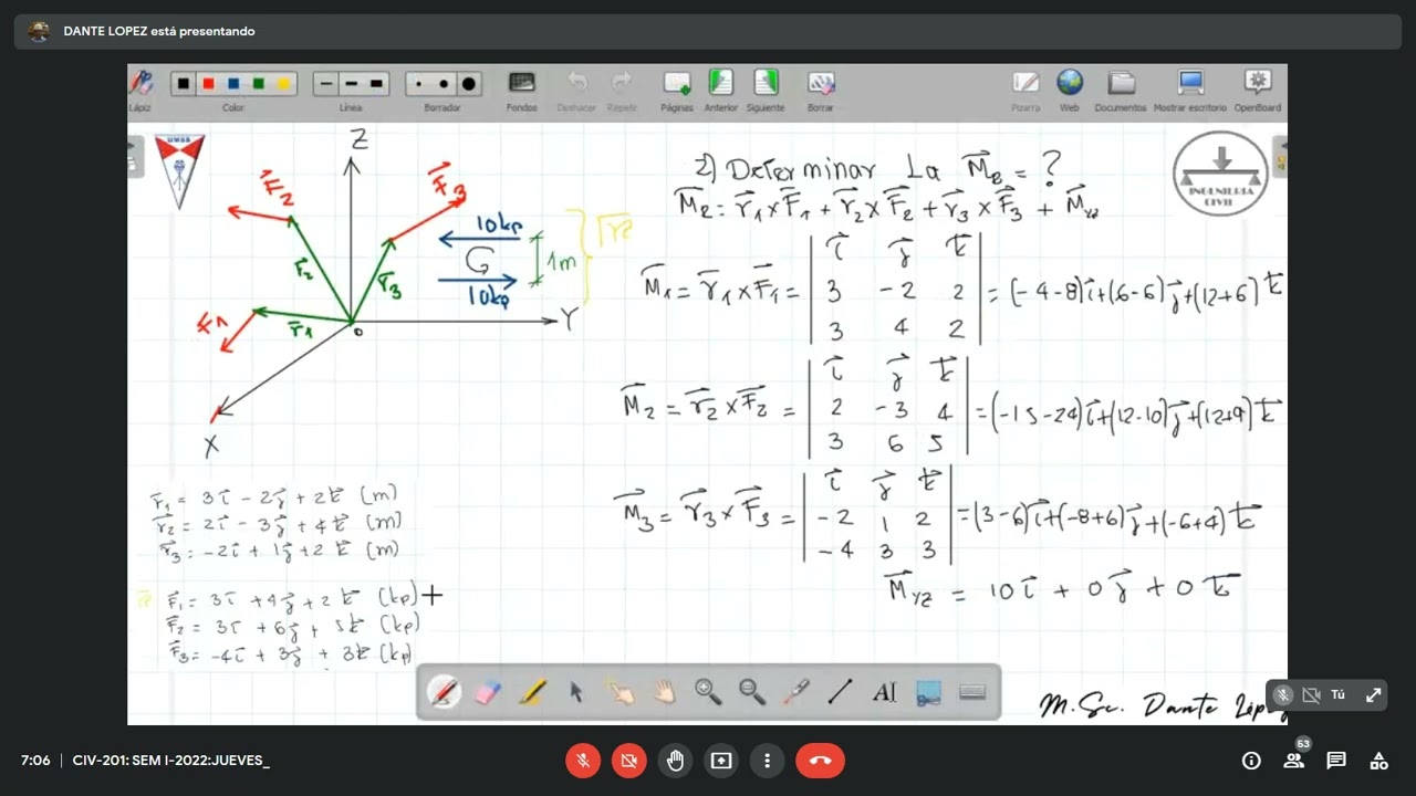
07-ESTRUCTURAS ISOSTÁTICAS Jueves 17/03/2022
481
The fundamental principles of static equilibrium state that for a body to be in equilibrium, the sum of all forces must equal zero (ΣF = 0) and the sum of all moments about any point must equal zero (ΣM = 0). These conditions must be satisfied simultaneously for the body to remain at rest. The instructor explains that these principles form the basis for analyzing any static structure and solving for unknown reactions.
Click to watch →
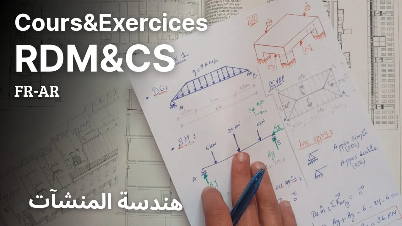
La Charge trapézoïdale simplifiée ! Calcul des appuis (RDM & CS) !🏗️📐
812
The fundamental principles of static equilibrium require that the sum of all forces and the sum of all moments acting on a structure must equal zero. For a structure in equilibrium: ΣF_x = 0 (sum of horizontal forces), ΣF_y = 0 (sum of vertical forces), and ΣM = 0 (sum of moments about any point). These equations form the basis for determining unknown reactions in statically determinate structures.
Click to watch →
Deep Dive
The concept of vector resolution, specifically how vertical loads can be redirected into lateral or diagonal forces.
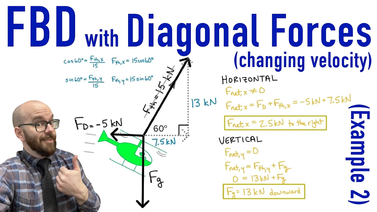
Free Body Diagram with Diagonal Forces (helicopter flying; changing velocity)
2.3K
Diagonal forces must be resolved into horizontal and vertical components using trigonometry. For a 15 kN thrust at 60 degrees: horizontal component = 15 × cos(60°) = 7.5 kN; vertical component = 15 × sin(60°) = 13 kN. After resolution, discard the original diagonal force value. This process transforms complex angled forces into simpler perpendicular components that can be analyzed independently in each axis.
Click to watch →
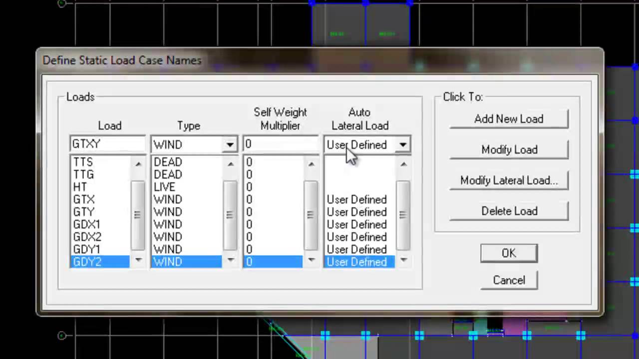
Etabs - Thiết kế nhà cao tầng - 03 - Tính toán và khai báo tải trọng Gió, Động đất
75.8K
Diagonal direction loads require trigonometric resolution into X and Y components. For XY direction: X-component = cos(π/4), Y-component = sin(π/4). For YX direction: X-component = cos(3π/4), Y-component = sin(3π/4). This trigonometric resolution ensures accurate representation of diagonal seismic forces. The software allows copying and modifying load values to assign resolved components. This process is essential for structures with diagonal bracing or asymmetric configurations where diagonal seismic forces must be properly captured.
Click to watch →

Design & Example problems on Purlins
2.8K
Structural loads can be resolved into vertical and horizontal components for analysis. Vertical loads (such as dead load and live load) act perpendicular to the horizontal plane, while horizontal loads (such as wind and seismic loads) act parallel to the horizontal plane. This resolution is essential for analyzing structures in different orientations and for determining the appropriate structural system to resist the applied loads.
Click to watch →

الصف العاشر 🔟 فيزياء 🧲 || تأسيس الفصل الثاني: الحصة الثانية مع أ. #مهند_القرم
123
Vector resolution (تحليل المتجهات) is the process of breaking down a single vector into two perpendicular components: one horizontal (along the x-axis) and one vertical (along the y-axis). A vector has two functions: it can lift an object vertically (perpendicular component) and move it horizontally (horizontal component). These two components together are equivalent to the original vector.
Click to watch →
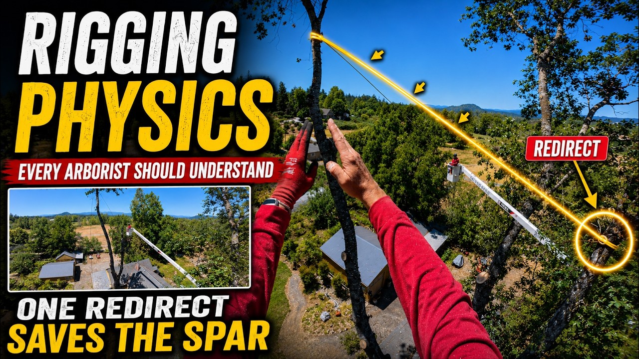
Rigging Physics Every Arborist Should Understand
3.1K
In rigging systems, a redirect pulley distributes forces by creating a triangular load path that pushes weight into the strength of the stem rather than pulling it straight down, which prevents structural failure; without a redirect, both weights would apply force straight down on the end of the structure, causing it to break.
Click to watch →
Deep Dive
Fundamental material properties of stone, masonry, and mortar, including their strength profiles under different loading conditions.
CI5223 - Propiedades de la albañilería - 08/11/2022
135
Workability (trabajabilidad) is the most important property for good masonry execution, consisting of fluidity (fluidez) and consistency (consistencia). Fluidity, measured by the Abrams cone test, refers to the mortar's ability to flow and spread. Consistency, measured by the Casagrande method, refers to resistance to deformation. These properties are antagonistic: greater water content increases fluidity but decreases consistency, while greater granular content decreases fluidity but increases consistency. Retentivity (retentividad) is the capacity to retain mixing water against absorption by masonry units, depending on fine particle content, mixing time, and incorporated air. Density of conventional mortars ranges from 1.7 to 2.4 tons per cubic meter. Compressive strength depends on component dosing, sand-to-cement ratio, water-to-cement ratio, and age. Flexural strength is measured using the RILEM test with a 4x4x16 cm beam specimen. Adhesion (adherencia) is the resistance at the interface between masonry units and mortar, determined by component dosing, cement content, fresh mortar properties, and workability. There is a direct relationship between retentivity and adhesion - mortars with higher retentivity achieve greater adhesion. Cement mortars reach 100% strength at 28 days, with 70% at 7 days. Lime mortars require approximately 90 days to reach maximum strength due to slower curing. Masonry walls are tested for shear resistance using diagonal compression. Good adhesion is indicated when failure occurs through the units (wall breaks apart with units failing), rather than mortar joints failing.
Click to watch →

آموزش طراحی و ارزیابی سازه های بنایی
666
Critical material properties include elastic modulus (Russian brick: 0.7f'ₘ ≤ 220 GPa; concrete blocks: 0.9f'ₘ ≤ 220 GPa), shear modulus (G = 0.1E for blocks, G = 0.25E for concrete/mortar, G = 0.1E for brick/plaster), thermal expansion coefficients (brick: 7.2×10⁻⁶/°C, blocks: 8.5×10⁻⁶/°C), and creep coefficients (blocks: 36×10⁻⁴/MPa, brick: 1.5×10⁻⁴/MPa). Two methods determine compressive strength: prism testing and estimation from unit strength and mortar type. Mortar classification includes Type S (≥22 MPa for below-grade) and Type M (≥10 MPa for general use). Masonry assembly strength combines unit and mortar properties—for example, Russian brick at 9 MPa with Type S mortar yields f'ₘ = 16.2 MPa. Flexural tensile strength varies by mortar type (0.69 MPa for Type S/M, 0.52 MPa for Type M). Shear resistance uses V = Vₙ × A, with Vₙ derived from flexural tensile strength, joint thickness, and effective height. Base shear capacity equals Qₙ = f'ₙₑ × a × hₑ. Lateral stiffness combines flexural and shear deformation: K = 1 / [(hₑ³/(3EI)) + (hₑ/(AVG))], with adjustment for walls containing openings.
Click to watch →
BUILDING CONSTRUCTION LECTURE 7#STRENGTH OF MASONRY JOINTS #UJVNL#DRAFTSMANSSCJE
2.4K
The compressive strength of masonry joints depends on three key factors: the cylinder strength of materials, the quality of materials (brick and mortar), and the size and shape of the masonry construction. Mortar, which binds building units together, comes in several types: lime mortar (with high plasticity but slow setting), cement mortar (providing the highest strength and most commonly used in modern construction), surkhi mortar (used when sand is unavailable to prevent shrinkage), and gypsum mortar (which improves lime mortar quality by adding cement). The IS code grades mortar into seven categories (M1-M7) based on minimum compressive strength, with M1 being the strongest at 10 N/mm² and M7 being the weakest at 2.5 N/mm².
Click to watch →
What Non-Engineers Need to Know about Concrete Masonry
116
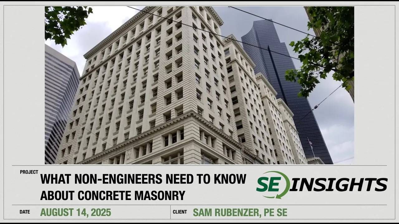
Masonry unit strength is determined using TMS 402/602 code tables, with engineers reorienting values to understand regional unit availability. Mortar types (M, S, N) have different properties: Type M and S are equivalent in assembly strength (0% difference), while Type N reduces strength by 10-15%. Mortar compressive test values differ from actual wall mortar due to water wicking and aspect ratio changes. Grout must be at least as strong as F'pr or 2,000 PSI. Masonry is excellent in compression while reinforcement handles tension, making them complementary materials.
Click to watch →

YIĞMA YAPILARIN ANALİZ VE TASARIMI DR MAHMUD SAMİ DÖVEN
1K
This section covers material properties and shear strength calculation for masonry buildings. Masonry elastic modulus can be determined through wall specimen testing or empirically as 750 times the characteristic compressive strength for normal masonry and 450 times for reinforced panels. Shear modulus is calculated as 40% of the elastic modulus. Masonry shear strength is calculated using empirical formulas: the initial shear strength (Fvk0) represents resistance at zero axial load, and the characteristic shear strength is calculated by adding 40% of the normal stress to the initial shear strength, with a maximum of 10% of compressive strength. Mortar mix design significantly affects strength: lime mortar (1 lime:3 sand) produces approximately 2.5 MPa, mixed mortar (1.5 lime:1 cement:8 sand) produces approximately 2.5-10 MPa, and cement mortar (1 cement:4 sand) produces approximately 8 MPa.
Click to watch →
Prerequisite Knowledge
- Concept 01Understanding the difference between compressive and tensile forces, and how various materials behave under these stresses.
- Concept 02Basic principles of static equilibrium, where the sum of all forces and moments acting on a structure equals zero.
- Concept 03The concept of vector resolution, specifically how vertical loads can be redirected into lateral or diagonal forces.
- Concept 04Fundamental material properties of stone, masonry, and mortar, including their strength profiles under different loading conditions.
Subsequent Learning
- Step 01The mathematics of the 'line of thrust' and how to calculate lateral thrust at the bridge abutments.
- Step 02Analysis of scour and hydraulic forces on bridge piers, explaining how running water affects foundation stability over time.
- Step 03Evolution of bridge design from static stone arches to modern long-span structures like suspension and cable-stayed bridges.
- Step 04Historic preservation and structural health monitoring of masonry structures, including techniques like retrofitting and grouting.
Stone Arch Bridge
Stone Arch Bridge
0:00Playing Section
- 1
Stone arch bridges endure floods without steel, relying on precise stone fitting.
- 2
Wooden frames shape arches, with stones interlocking to redirect force outward.
- 3
The keystone design presses tighter under load, ensuring lasting stability.
The Vulnerability of Masonry Arches: Scour, Tension, and Modern Load Limitations
While stone arch bridges are celebrated for their compression-based durability, they possess significant engineering limitations compared to modern steel and concrete structures. First, stone has virtually no tensile strength, making masonry arches highly vulnerable to seismic activity and uneven foundation settling. Second, despite their reputation for surviving floods, their thick instream piers restrict water flow, accelerating "scour"—the erosion of soil around foundations. Scour is a leading cause of bridge failure, and stone arches are highly susceptible to it. Finally, the massive self-weight of stone arches limits their maximum span length and efficiency, making them impractical for modern, wide crossings and dynamic, heavy transit loads.
Deep Dive
The mathematics of the 'line of thrust' and how to calculate lateral thrust at the bridge abutments.
Hamish Harvey – Understanding masonry bridges: a historical perspective
1.8K
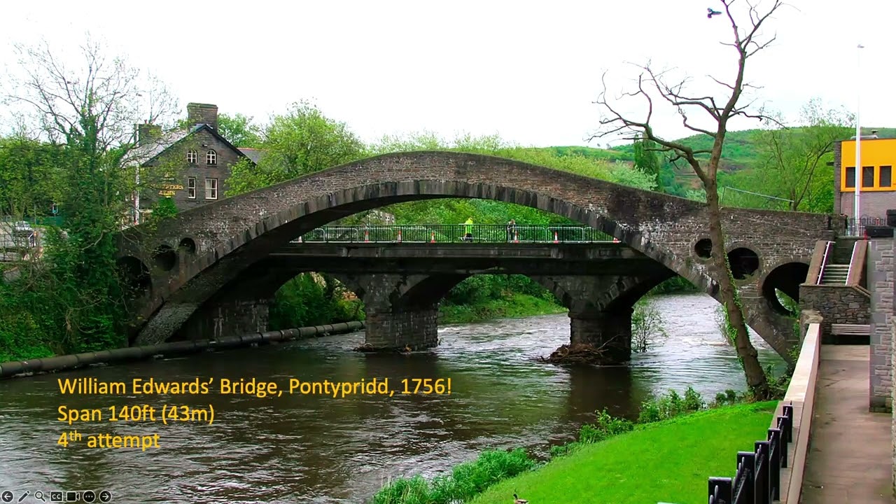
Peter Bow introduced a mostly graphical method for constructing lines of thrust, with some calculation involved. The most significant contribution was identifying that the maximum horizontal thrust is the resistance that the arch can give if the abutment pushes, while the minimum is the force that can be exerted by the arch on the abutments. This was the first time this distinction had been explicitly drawn out. He also identified that when arches meet at a pier with different geometries, the relationship between maximum and minimum at each location becomes critically important.
Click to watch →
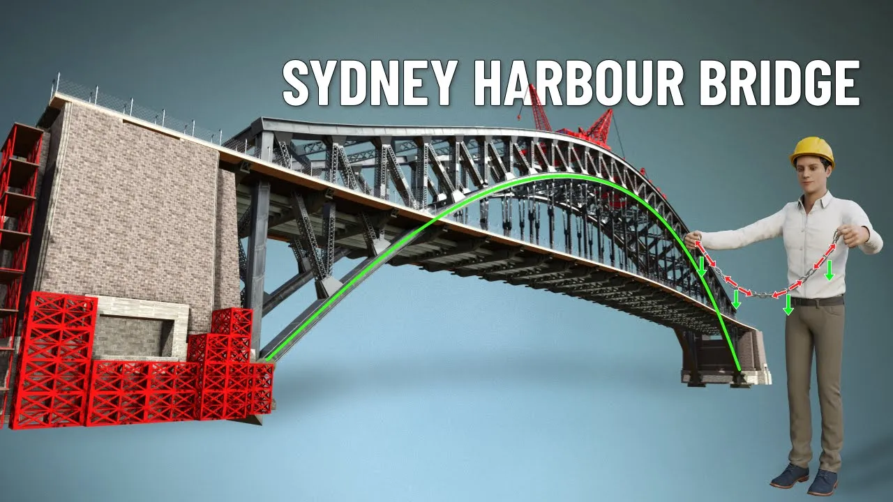
The Beautiful Engineering behind the Arch Bridges!
5.3M
When external loads like train weight act on an arch bridge, internal forces deviate from the center line. Engineers connect the positions of these internal forces to create something called a line of thrust. For good stability of arch bridges, engineers ensure that even under extreme load conditions, the line of thrust remains within the middle third of the arch section.
Click to watch →
![Ders 4E: Sürşarj Yükü ve Yeraltı Suyu Varlığında Yatay Zemin Basınçları / Rankine Teorisi [2021]](https://i.ytimg.com/vi/BTlNm9ihel8/hqdefault.jpg?sqp=-oaymwEmCOADEOgC8quKqQMa8AEB-AHUBoAC4AOKAgwIABABGGUgXChWMA8=&rs=AOn4CLChFsfSS-NcTsPBk6NRCAkBPxMpUQ)
Ders 4E: Sürşarj Yükü ve Yeraltı Suyu Varlığında Yatay Zemin Basınçları / Rankine Teorisi [2021]
3.3K
This section covers the complete calculation of total lateral thrust when surcharge, cohesion, and groundwater are all present. The total thrust is calculated by summing five components: surcharge (q × K_a × H), soil weight above water table ((1/2) × γ × H1² × K_a), effective stress below water table ((γ × H1 + (γ_sat - γ_w) × (H - H1)) × K_a × (H - H1)), hydrostatic water pressure ((1/2) × γ_w × (H - H1)²), and cohesion (2c√K_a × H). The point of application is found by taking moments of all components about the base, with each component acting at its respective centroid. For passive conditions, the same procedure applies with K_a replaced by K_p. The formulas require appropriate K_a or K_p values based on wall inclination and backfill slope conditions.
Click to watch →
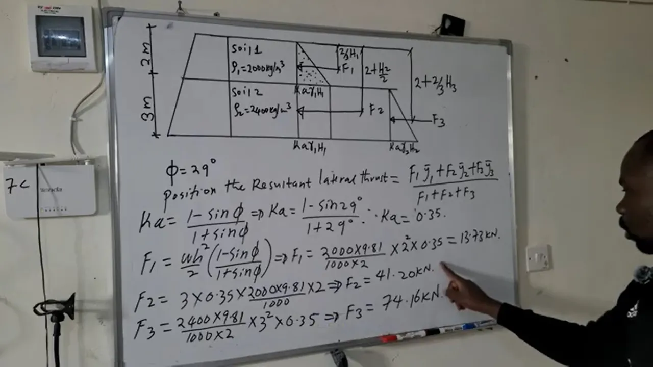
CALCULATION OF POSITION OF RESULTANT LATERAL THRUST OF RETAINING WALL
116
The position of the resultant lateral thrust from the top (ȳ_top) is calculated using the weighted average formula: ȳ_top = (F1×ȳ1 + F2×ȳ2 + F3×ȳ3) / (F1 + F2 + F3), where ȳ1 = (2/3)H1, ȳ2 = 2 + (H2/2), and ȳ3 = 2 + (2/3)H3. Substituting values: F1 = 13.73 kN, ȳ1 = 1.33m; F2 = 41.02 kN, ȳ2 = 3.5m; F3 = 74.6 kN, ȳ3 = 4m. The resultant position from the top is 3.66m, and from the base is 1.4m.
Click to watch →

Quabbin’s Keystone Bridge
991
Calculating the line of thrust in stone arches traditionally uses graphical methods on graph paper, where thrust vectors for each stone are drawn and accumulated into a continuous curve. Computer programs now perform this calculation mathematically, offering greater precision. Accurate mapping of stone positions is essential for both approaches, as errors in stone location data propagate through the entire analysis.
Click to watch →
Deep Dive
Analysis of scour and hydraulic forces on bridge piers, explaining how running water affects foundation stability over time.

HEC RAS Lecture 10 - Bridge Scour
201
Bridge scour depth is determined by analyzing contraction scour (flow acceleration under the bridge), pier scour (around bridge piers), and abutment scour using HEC-RAS software; the analysis shows that higher flow rates significantly increase scour depth (from approximately 5 ft to 8.5 ft in the demonstration), while coarser bed material (larger D50/D95 values) reduces scour depth, demonstrating the critical relationship between hydraulic conditions and bridge foundation stability.
Click to watch →
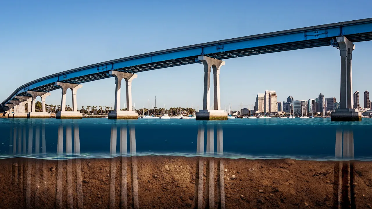
Why Bridges Don't Sink
4.1M
Structures experience loads in multiple directions beyond vertical forces. Buildings face horizontal loads from wind, while bridges encounter lateral loads from flowing water, ice, boats contacting piers, and uplift forces from floods due to buoyancy or strong winds. Additionally, scour—the erosion of soil around bridge foundations caused by water flow—can dramatically change the foundation environment over time. Engineers must predict these changes and design foundations capable of accommodating them throughout the structure's lifespan.
Click to watch →
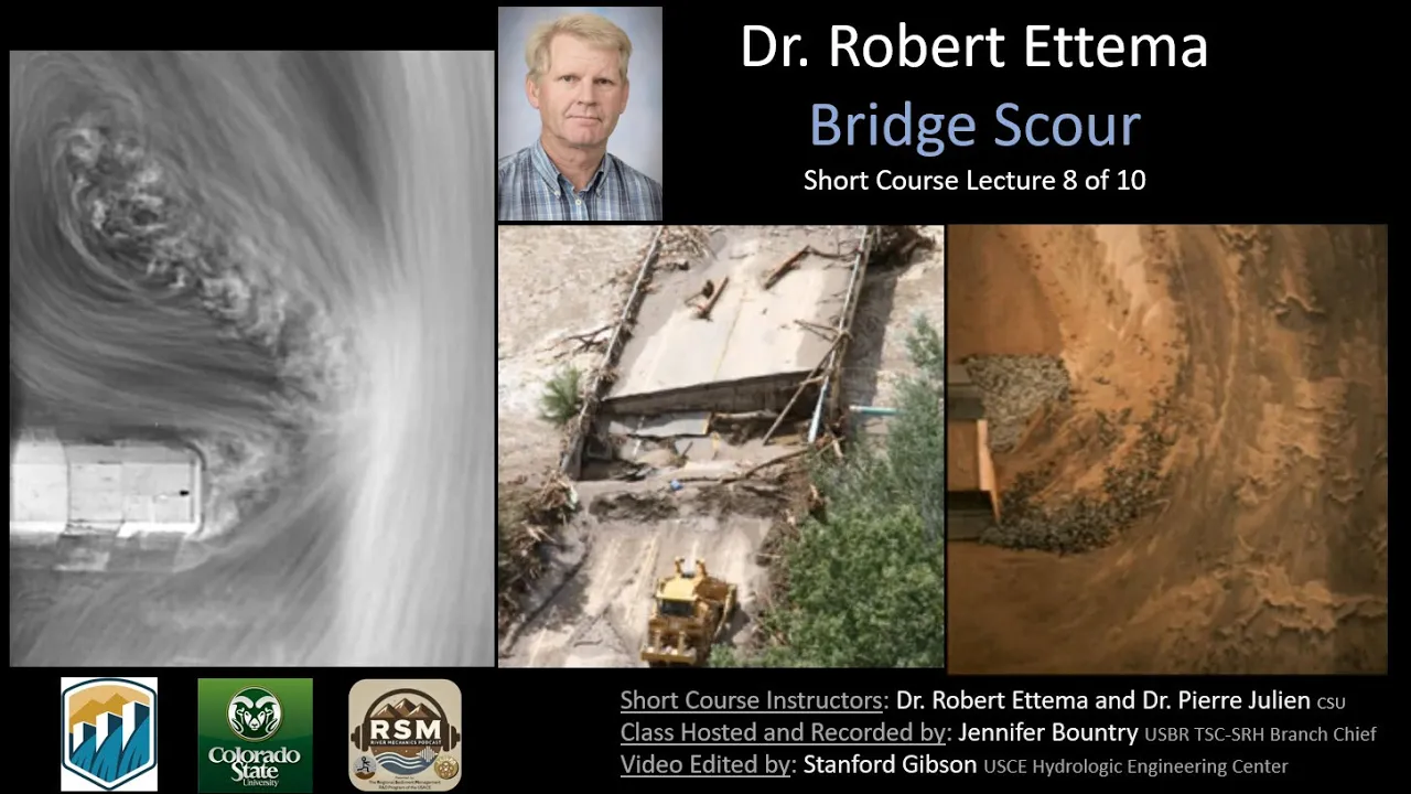
Dr Rob Ettema on Bridge Scour (Piers and Abutments) (USBR Short Course 8)
319
Bridge scour at piers and abutments results from complex interactions between turbulent flow fields and erodible boundaries, requiring integrated hydraulic and geotechnical analysis; pier scour involves junction flow phenomena with horseshoe vortices and varying depth-to-diameter ratios affecting scour depth, while abutment scour is primarily a geotechnical slope stability problem where insufficient soil support causes failure before significant hydraulic scour develops, necessitating graduated design approaches from empirical formulas to physical/numerical modeling for complex cases.
Click to watch →

JBA Trust hydraulic flume showing how engineered structures affect flow in rivers (full video)
3.8M
Bridges can be designed with straight piers supporting the structure on top or angled piers positioned at an angle to river flow. Straight piers cause water levels to increase upstream (from 2cm to 4.5cm) while decreasing downstream, with noticeable scour effects at the pier base. Angled piers further increase upstream water levels (to 6cm) while reducing downstream levels (to 1cm), and distribute scour effects across both sides of the pier. The angled design reduces localized scour intensity compared to straight piers.
Click to watch →
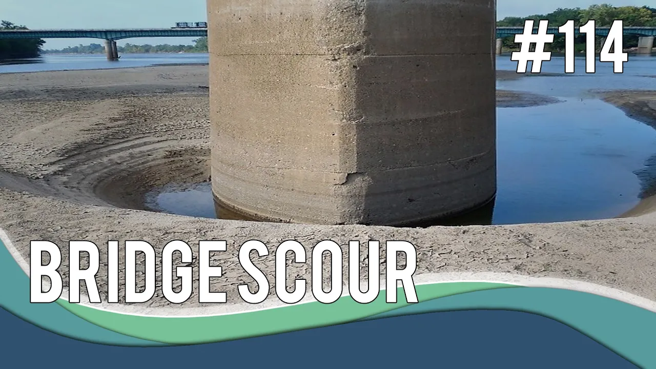
Estimating bridge hydraulics and scour
14.3K
Bridge scour requires interdisciplinary teams combining hydrologic, geomorphic, hydraulic, geotechnical, and structural expertise. The worst-case scour concept mandates evaluating all flows equal to or less than the design event to identify maximum scour potential. Total scour comprises three components: long-term degradation from downstream infrastructure changes (up to 15-20 feet of bed lowering documented), general contraction scour from reduced flow area, and local scour at piers and abutments. Lateral channel migration must also be assessed with fall line elevation as reference. Contraction scour calculations require identifying sediment-transporting width (not full inundation width) and associated discharge, distinguishing between live bed and clear water conditions using critical velocity equations. Abutment scour uses NCHRP 2420 method, modifying contraction equations with factors based on abutment geometry and proximity to main channel. Local pier scour results from flow acceleration creating vortices; unlike contraction scour, local maximum values from 2D models should be used. Round piers are recommended for new bridges, with rules of thumb suggesting 2.4x pier width for Fr<0.8 and 3x for Fr>0.8.
Click to watch →
Deep Dive
Evolution of bridge design from static stone arches to modern long-span structures like suspension and cable-stayed bridges.
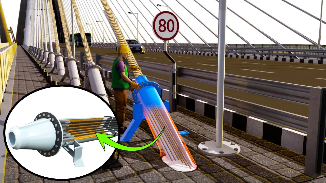
How are Bridges Built over the Ocean?
1.3M
Cable-stayed bridges trace back to Fosto Verancio's 16th-century theoretical design, but early 19th-century implementations failed catastrophically—the Dryberg Abbey Bridge collapsed in 1818, and the Zali River Bridge collapsed in 1824. This led to nearly 130 years of preference for truss, arch, and suspension bridges. In 1955, Franz Dischinger revived the technology with the Stromson Bridge in Sweden, introducing fan cable arrangements, force calculations, and prestressed concrete. His success triggered global proliferation, with the US joining via the Ed Hendler Bridge in 1978. Modern FEA models now enable optimal cable tensioning, allowing slender girders with reduced bending moments. The Hong Kong-Zhuhai-Macau Bridge exemplifies this evolution at 55 km total length, featuring four artificial islands, a 6.4 km underwater tunnel, and three cable-stayed bridges spanning 29.6 km.
Click to watch →
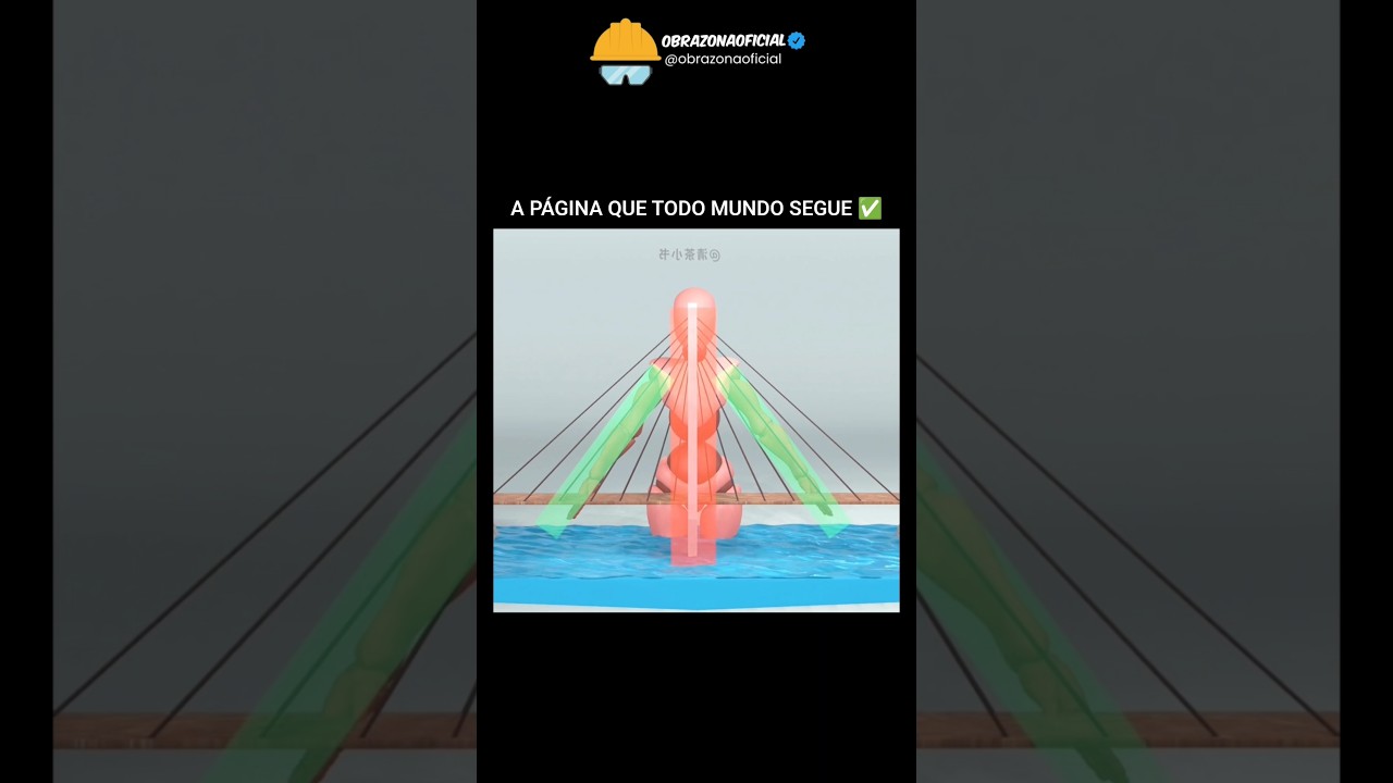
estrutura de uma ponte explicada em 3d
1.2M
This video demonstrates the evolution of bridge engineering through a 3D visualization: starting with a simple beam that sags under its own weight, then adding pillars to reduce curvature (though this obstructs river flow), then suspending the beam with cables from a central tower (like carrying a heavy load with arms), and finally moving the tower to the riverbank and angling the cables to create a modern cable-stayed bridge that is both aesthetically pleasing and structurally efficient.
Click to watch →

The Evolution of Bridge Engineering: From Ancient Roots to Modern Marvels
2.5M
The first bridges used plant-based materials like vines, rope, and wooden planks, still used in Himalayan foothills. Stone became dominant in less forested areas, with some prehistoric bridges still standing. The Romans perfected stone arch construction using centering (wooden semicircles) to support stone blocks during building. The Pont du Gard, built in the first century AD, is the highest Roman aqueduct bridge at 47.6 meters long, 6 meters high, with a 275-meter span. Its three tiers contain 6, 11, and 35 arches respectively. Vitruvius authored the only surviving treatise on antiquity architecture, providing an exposition of Roman construction art. The aqueduct faced a critical challenge: the chosen spring was only 17 meters higher than the arrival point, requiring an extremely gentle slope of 24 centimeters per kilometer. Between the Roman Empire and Middle Ages, there was little technical progress. The real break came in the late 17th and early 18th centuries with lighter bridge designs. Semicircular arches with centering were replaced by elliptic arches, offering wider spans and enabling bridges to cross greater distances. Jean-Rodolphe Perronet, considered the father of modern engineering, was the first to understand the true mechanics of stone arched bridges. He established that each arch was not freestanding and that thrust was shared between spans, allowing pile thickness to be considerably reduced. In the late 18th and early 19th centuries, mastery of iron revolutionized bridge building. Iron was approximately 60 times more resistant to pressure and thrust than stone, enabling lighter structures. Iron resisted tensile strength as well as pressure, allowing architects to drop the arch, which had been dominant since Roman times. The Garabit Viaduct, designed by Gustave Eiffel, exemplifies this era—565 meters long, 120 meters high, with a 165-meter main arch span. Half was preassembled in workshops near Paris, while the other half was hot riveted on-site. The riveted iron girders were assembled with rivets—small shafted iron fasteners heated to red or white hot and hammered flat. Engineers then turned to steel, an alloy of iron and carbon, which was much more resistant. The development of steel transformed metalwork from craft to science. Unlike iron, steel could be welded, totally transforming assembly technology. The suspension bridge, where the road deck hangs below wire suspension cables anchored in abutments, represents another revolutionary approach. The main challenge was ensuring steel wire quality to prevent snapping. The Brooklyn Bridge in New York, designed by John Roebling, is a legendary example spanning 1,825 meters, beating all span and height records. Construction began in 1870. John Roebling died of tetanus after a ferry crushed his foot. His son Washington Roebling took over and went down into the caissons to help workers dig out muck and rocks. He contracted caisson disease (decompression sickness) and was laid up in bed. His wife Emily Roebling transferred all information from Washington to the workers, becoming one of the first women civil engineers instrumental in building the bridge. The foundations employed innovative caisson construction—two giant wooden caissons measuring 50 meters long by 30 meters wide, with granite blocks gradually sinking them to the riverbed. At 30 meters depth, compressed air was injected to resist water pressure. Laborers dug for several months in this damp, cramped, pressurized space. Contractors and workmen suffered from caisson disease because almost everyone who went into the caisson came out in extreme pain. Decompression sickness occurs when a person comes out of pressurized water too quickly. The nitrogen in the blood comes out too fast, similar to opening a soda bottle too quickly. The gases settle into the joints, causing extreme pain. The Brooklyn Bridge's main cables contain 5,434 wires each, making a 15 and 3/4 inch cable. Each cable can withstand a pull tension of 25 million pounds. The bridge was the first suspension bridge in the world to use galvanized steel wires—steel coated with zinc. Zinc oxidizes but doesn't rust, protecting the steel underneath. After 13 years of work, the bridge was completed and inaugurated on May 21, 1883, as a national event. The first Tacoma Narrows Bridge in Washington state collapsed under wind effects. Inaugurated on July 7, 1940, the bridge started oscillating up and down from the outset. During summer 1940, people visited to see it swaying, making it a tourist attraction. In November, during a storm with 70 km/h winds, the deck started twisting from side to side with an amplitude of almost 9 meters. After an hour, the central section collapsed into the Tacoma Narrows. The collapse claimed no victims except a terrified dog locked in a car. When wind blew on the bridge, air pressure was exerted on the edges of the deck, transferring energy into the structure and causing the roadway to bend and sway. After the collapse, architects and engineers began studying wind impact more deeply. It wasn't until the 1970s that aerodynamics became a science in its own right. From then on, bridge decks were streamlined to facilitate air flow around the structure, preventing any risk of swaying.
Click to watch →

¿Cómo se construyen los puentes sobre el océano?
411.7K
Bridge technology selection depends on span requirements and environmental conditions. Suspension bridges achieve longest spans (Golden Gate: 1,280m; Akashi Kaikyo: nearly 2km) but require complete main cable installation before deck work. Cable-stayed bridges span 150-600m with superior constructibility, allowing simultaneous deck and tower construction. Arch bridges provide exceptional strength for heavy loads. Historical failures in early cable-stayed designs (1818-1824) delayed their adoption until Franz Dinger's 1955 Stromsund Bridge revival.
Click to watch →

Evolution of bridge engineering 📈 #shorts
195.5K
Bridge engineering has evolved from simple stone slab bridges to sophisticated multi-arch structures through iterative problem-solving: starting with basic stone slabs on piers, which broke under load; progressing to arched designs using interlocking triangular stones bound by metal bands; then adding straight pathways with railings for accessibility; and finally implementing multiple smaller arches to reduce weight by 70% while increasing flood resistance and structural strength, enabling bridges to withstand natural disasters for centuries.
Click to watch →
Deep Dive
Historic preservation and structural health monitoring of masonry structures, including techniques like retrofitting and grouting.

Grouting a Block Wall
92.6K
When grouting masonry block walls, it is essential to work in vertical lifts of 4-6 feet to ensure proper grout consolidation around reinforcing steel; taller lifts risk inadequate consolidation, so cleanouts (holes drilled in the block face) allow visual confirmation that grout reaches the rebar and footing, ensuring structural integrity.
Click to watch →

STRENGTHENING AND RETROFITTING TECHNIQUES OF TRADITIONALLY BUILT STRUCTURE (ERBC- chapter - 5)
69.1K
Retrofitting is the process of strengthening and repairing existing damaged or weak structures to make them earthquake-resistant, and it encompasses various techniques including grouting for crack repair, shotcrete application, jacketing with steel plates, prestressing, shear wall addition, infill wall installation, and fiber-reinforced polymer (FRP) systems, which can be classified into local retrofitting (individual member repairs) and global retrofitting (comprehensive building-level strengthening).
Click to watch →

Estruturas Mistas: Alvenaria Estrutural X Concreto Armado
6.2K
Determining which walls should be structural requires considering multiple factors: building height (taller buildings need more structural walls for lateral stability), slab type (solid, ribbed, or prestressed), and building geometry. Structural walls serve the critical function of lateral stability (contraventamento). The instructor explains that fewer structural walls allow more flexibility for future renovations but may increase slab costs due to larger spans. Grouting (grautagem) increases wall resistance at critical points. There are two types: parametric grouting (used at wall intersections and around doors/windows where stress concentrations occur) and calculated grouting (determined through structural calculations when walls don't meet resistance requirements). The instructor emphasizes that grouting should use specialized grout with shrinkage control additives. Using regular concrete for grouting is incorrect because it will shrink and cause fissures.
Click to watch →

This is an IMPORTANT Part of my Fountain Build!
17.1K
This segment covers masonry finishing techniques, grouting practices, and project completion for the block wall enclosure. Key topics include horizontal rebar placement every 3-6 courses, grouting practices for freestanding vs retaining walls (cells with rebar vs complete solid grouting), and joint finishing methods. Exterior joints are sponged for cohesive appearance, while interior joints can be raked with roller skate tools for decorative finishes. The video explains masonry tender responsibilities including material management, mortar maintenance, and crew support. Concrete placement techniques with mortar dams to prevent spillage are demonstrated. The segment concludes with electrical integration planning, visual impact considerations for landscape placement, and the critical importance of proper waterproofing for the fountain project.
Click to watch →

Technologia wykonania maszynowych tynków gipsowych Knauf
949.2K
For absorbent surfaces such as masonry from lime mortar, silicate bricks, and autoclaved aerated concrete blocks, the grouting agent KN Gruntmittel is used. This agent is designed for indoor use on highly absorbent substrates that would otherwise cause plaster drying issues. The grouting agent is diluted in a ratio of 1:1 to 1:5 depending on substrate absorbency, with 1:3 being the most common ratio. After preparation, the grouting agent is applied evenly to the wall surface. Grouting agents are dispersions that are vapor-permeable, preserving the activity of the building element.
Click to watch →
Stone Arch Bridge
Stone Arch Bridge
0:00- 1
Stone arch bridges endure floods without steel, relying on precise stone fitting.
- 2
Wooden frames shape arches, with stones interlocking to redirect force outward.
- 3
The keystone design presses tighter under load, ensuring lasting stability.
The Vulnerability of Masonry Arches: Scour, Tension, and Modern Load Limitations
While stone arch bridges are celebrated for their compression-based durability, they possess significant engineering limitations compared to modern steel and concrete structures. First, stone has virtually no tensile strength, making masonry arches highly vulnerable to seismic activity and uneven foundation settling. Second, despite their reputation for surviving floods, their thick instream piers restrict water flow, accelerating "scour"—the erosion of soil around foundations. Scour is a leading cause of bridge failure, and stone arches are highly susceptible to it. Finally, the massive self-weight of stone arches limits their maximum span length and efficiency, making them impractical for modern, wide crossings and dynamic, heavy transit loads.
Understanding the difference between compressive and tensile forces, and how various materials behave under these stresses.
Basic principles of static equilibrium, where the sum of all forces and moments acting on a structure equals zero.
The concept of vector resolution, specifically how vertical loads can be redirected into lateral or diagonal forces.
Fundamental material properties of stone, masonry, and mortar, including their strength profiles under different loading conditions.
The mathematics of the 'line of thrust' and how to calculate lateral thrust at the bridge abutments.
Analysis of scour and hydraulic forces on bridge piers, explaining how running water affects foundation stability over time.
Evolution of bridge design from static stone arches to modern long-span structures like suspension and cable-stayed bridges.
Historic preservation and structural health monitoring of masonry structures, including techniques like retrofitting and grouting.
636.8K views7.7Klikes1:27@orawansuksaiOriginal Release: 2026-04-14
This bridge has no steel, no rebar, yet it can survive floods for hundreds of years. All it uses is stone. This is called a stone arch bridge. It looks like it has no support, yet it spans across fast-moving rivers. So, how is it even built? The secret starts here. They don't begin with the stones. They build a wooden frame first. Workers set up timber supports on both sides of the river, then construct a full arch-shaped scaffold, basically a temporary mold for the bridge. Only then do they start placing stones, and every stone matters.
They're carefully shaped, sometimes even carved with grooves, so they lock into each other like a puzzle. But, the most important detail is the shape. Wider on top, narrower at the bottom. This isn't for looks. It forces the entire structure into an arch, so when weight is applied, the force doesn't push downward. It gets redirected along the curve of the arch, spreading outward into the supports on both sides. The heavier the load, the tighter the stones press together, which makes the bridge even more stable. Once all stones are in place, they fill the gaps with mortar and finish the surface. Then comes the final step. They remove the wooden frame. If the structure works, the bridge stands on its own. If it doesn't, it collapses immediately. And the ones that survive, they don't just last years, they last centuries. Because the real strength was never the stone itself. It's the way every single piece handles force.
Up Next

0:49
Bridge Load Distribution: Structural Engineering Fundamentals
@eazysurveys
1.8K views•2026-05-28

30:32
Ultrasonic Transducers: Resonant Frequency Measurement and Horn Design
@imajeenyus42
229.9K views•2017-02-22

54:16
Polymer Environmental Degradation: Mechanisms & Stabilization
@iit
1.8K views•2012-07-10

33:39
How a Student's Question Saved a NYC Skyscraper from Collapse
@veritasium
22.8M views•2025-04-26
Related Study Plans & Knowledge Roadmaps
Structured learning paths in Engineering
engineering
Building Acoustic Levitators: Physics & Arduino
01The Physics of Sound and Standing Waves
02Piezoelectric Transducers and H-Bridge Drivers
03Arduino Programming: Generating 40 kHz Signals
+ 2 more learning modules
14h5 modules
Explore Roadmap
engineering
Building Peltier Cloud Chambers: Particle Tracks
01Cosmic Rays & Cloud Chamber Physics
02Thermoelectric Cooling (TEC) Fundamentals
03Custom Liquid-Cooling Loop Design
+ 2 more learning modules
18h5 modules
Explore Roadmap
engineering
Yagi-Uda Antennas: Modeling, Build & VNA Test
01Introduction to RF and Antenna Fundamentals
02Yagi-Uda Antenna Design Principles
03Antenna Modeling and Simulation in 4NEC2
+ 2 more learning modules
18h5 modules
Explore Roadmap
engineering
ECG Monitor Design: Op-Amps, Filters & Noise
01Electronics & Breadboard Basics
02Op-Amps and Instrumentation Amplifiers
03Bioelectricity and ECG Fundamentals
+ 2 more learning modules
18h5 modules
Explore Roadmap