

















![【オペアンプ】初歩のインスツルメンテーションアンプ/差動増幅回路【使い方と活用事例】 / First step of the Instrumentation amplifier [Eng sub]](https://i.ytimg.com/vi/LJMUoNdCQKA/hqdefault.jpg)

An operational amplifier (op-amp) is an integrated circuit that amplifies small differential voltages between its input terminals to produce a larger output voltage, featuring two input terminals (inverting and non-inverting), one output terminal, and power supply pins, with common applications including inverting and non-inverting amplifiers, comparators, integrators, and differentiators.
Operational Amplifier (Op-Amp) Explained – Basics & Applications
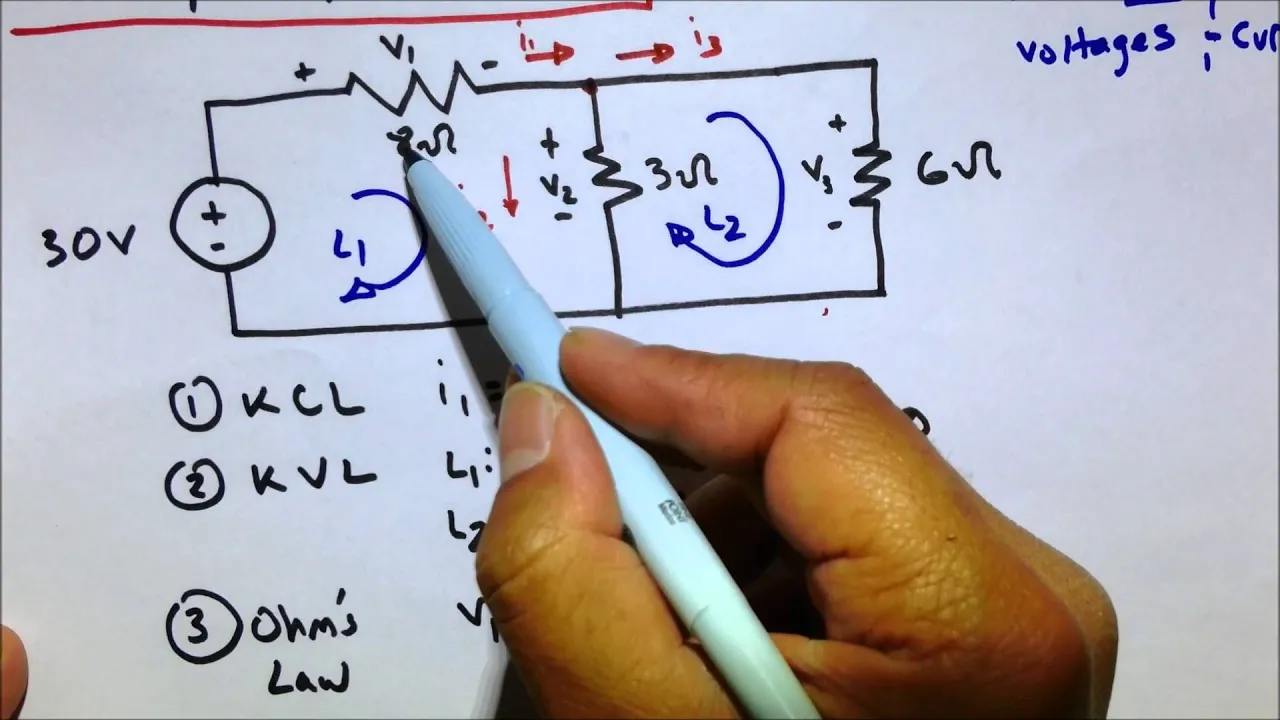
Added:Fundamental DC circuit analysis laws, specifically Ohm's Law and Kirchhoff's Current and Voltage Laws (KCL/KVL).
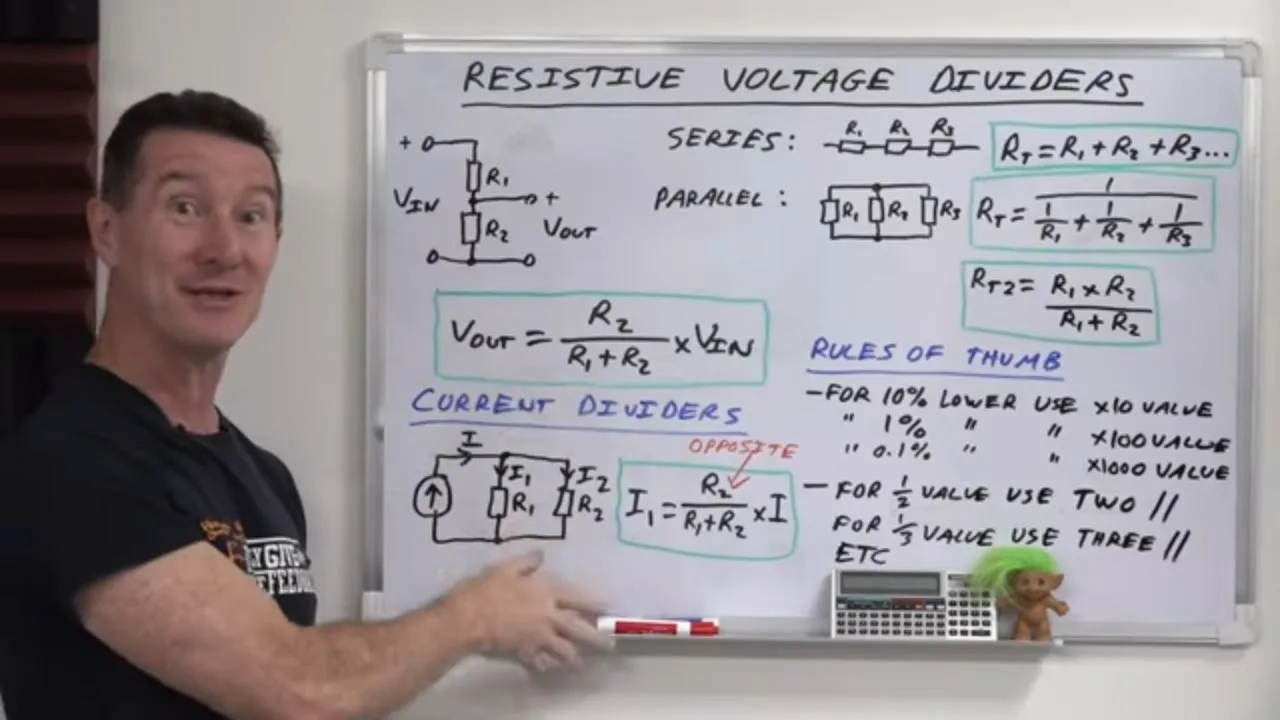
Understanding the behavior of passive electronic components, particularly resistors and voltage divider networks.
The concept of differential voltage (measuring the potential difference between two nodes rather than relative to ground).
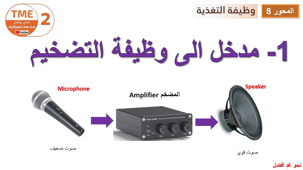
Basic familiarity with electronic signals and the concept of signal amplification.
Advanced mathematical op-amp circuits, including summing amplifiers, integrators, and differentiators.
Real-world, non-ideal op-amp limitations such as input offset voltage, bias currents, slew rate, and Gain-Bandwidth Product (GBP).
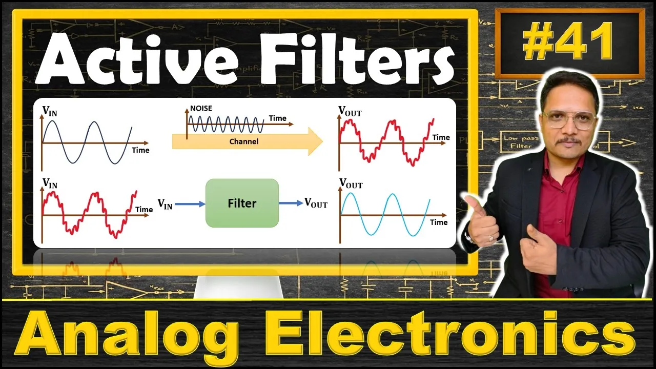
Active filter design (low-pass, high-pass, and band-pass filters) using operational amplifiers.
Practical applications such as instrumentation amplifiers, sensor signal conditioning, and audio pre-amplifier circuits.
856 views31likes10:07Original Release: 2023-10-22
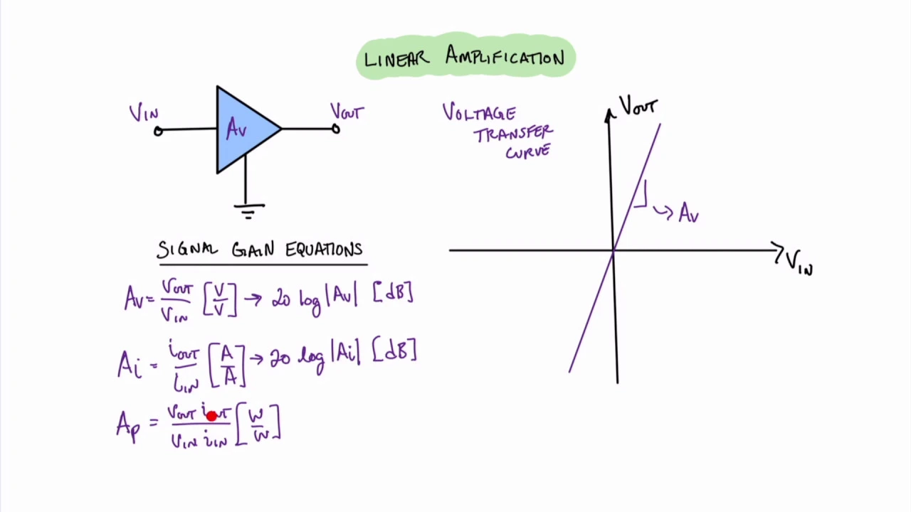
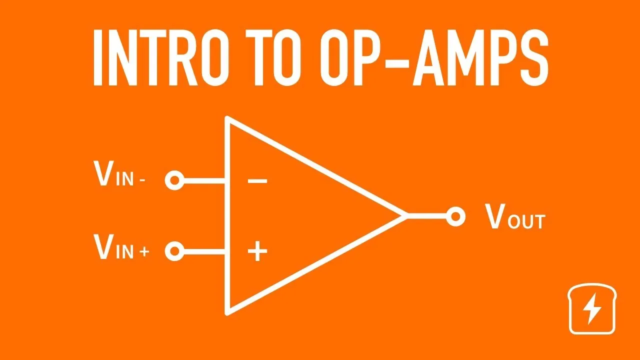
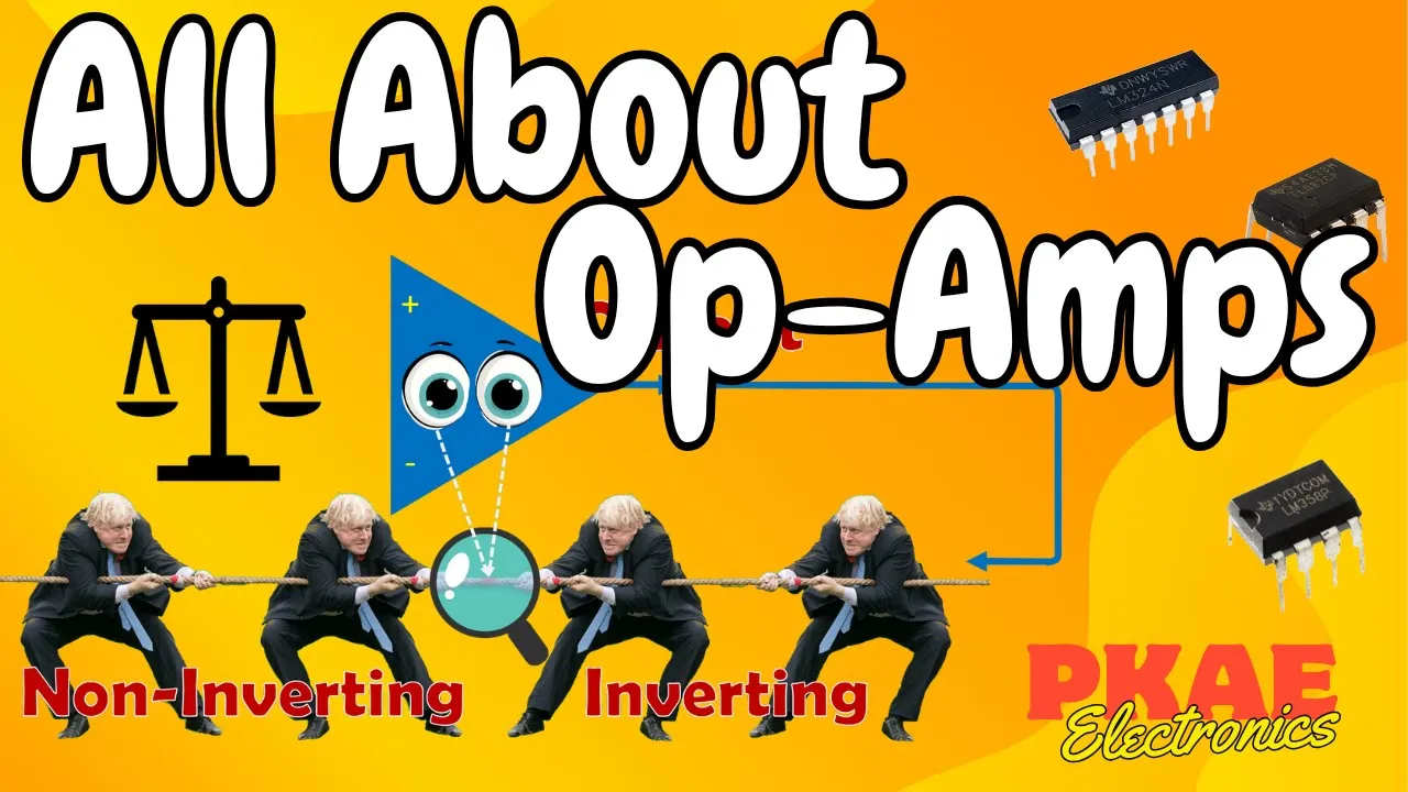
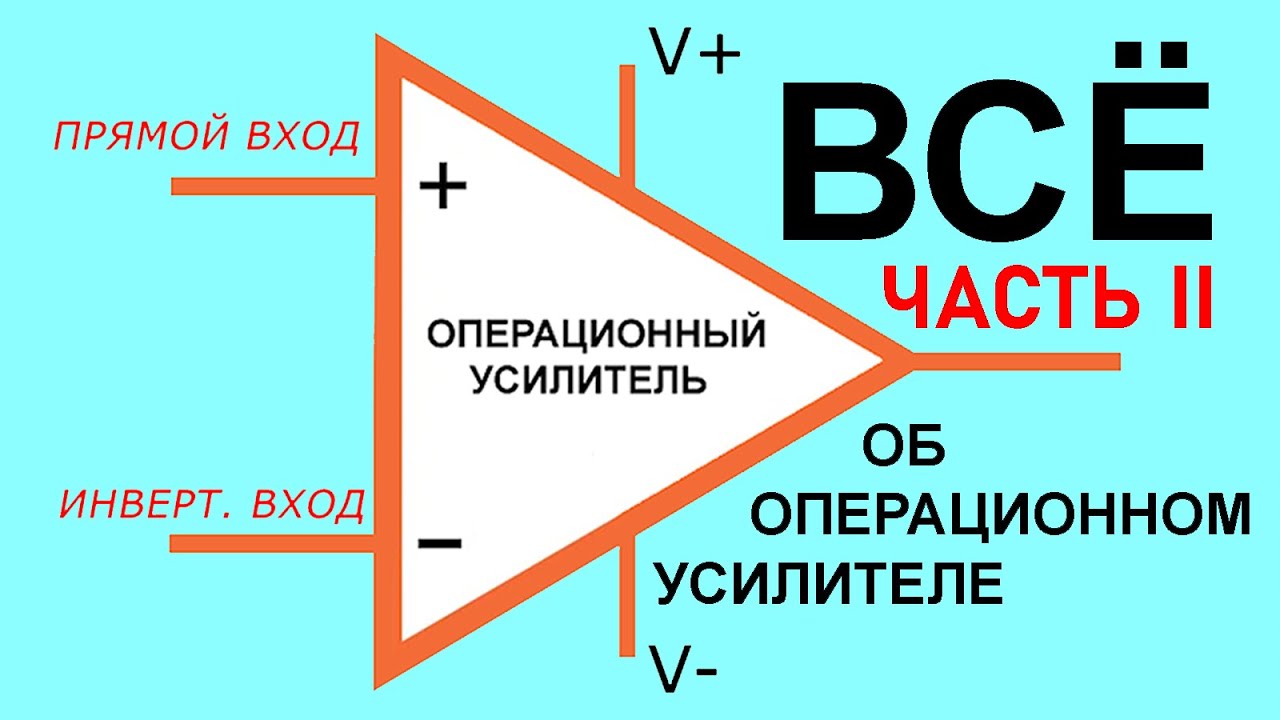
in this video we'll introduce you to one of the most versatile and widely used electronic devices in the field of analog circuitry the operational amplifier often referred to as an op amp so before we dive into the details let's understand what an operational amplifier is at its core an op amp is an integrated circuit that amplifies small differential voltages between its input terminals producing a much larger output voltage this amplification is achieved through the clever use of transistors and other electronic components packed onto a single chip on I see for clarification so as you can see that we have right here this is the sample of the operational amplifier we have right here the uh three main pins we are going to talk about them later and as you can see that this operational amplifier is an integrated circuit an IC so the simple for an op amp consists of two input terminals so as you can see right here we have these are the two input terminals denoted as the inverting terminal right here the one with the negative sign and the non-inverting input the one with the plus sign these are the two inputs of the operational amplifier and then we have the output terminal right here is the output terminal that the voltage comes out from additionally opms have power supply pins usually denoted as v+ and V minus as you can see that right here is the V Supply or voltage Supply Plus and the voltage Supply minus these are the pins where this IC this operational amplifier takes its operating voltage so as you can see right here we have the IC right here is the integrated circuit in which there is the operational amplifier or the op amp right here the pin number two and the pin number three are the two inputs of the operational amplifier the first one is the inverting and the second one is the non-inverting right here the pin number six is the output terminal then we have the pin number seven and the pin number four are the power supply for the operational amplifier right here we uh connect the Plus or the v+ to the uh operational amplifier and right here we connect the ground then we have these three pins the offset we are going to talk about the offset null pins we are going to talk about them later but right here there is a the pin number eight this is this pin is not connected to anything it's just for the symmetry of the IC when an input voltage is applied to the inverting terminal and non-inverting terminal the op amp Compares these voltages and amplifies the difference between them the Amplified output voltage is then fed back to the input in a closed loop configuration which allows for a wide range of appli uh applications such as amplification filtering signal conditioning and more we are going to talk about every one of them later so as you can see right here we have the operational amplifier and this is the connection for the operational amplifier right here we have the two input terminals right here we have the inverting terminal and this is the non-inverting terminal we have right here is an input signal this is an alternating signal so we need to amplify this signal so the connection of the operational amplifier we are going to talk about in details later but first as you can see that we have right here is this resistance and a another resistance that called a feedback resistor we are going to talk about later but as you can see that the input signals goes to the inputs of the operational amplifier and the operational amplifier take takes the difference between these two inputs and then amplify the difference between them so as you can see that the signal is going to be comes out inverted so as you can see that the signal started from the 0o point and Rising right here started from the 0o point and then decreased so now let's dive into a practical demonstration of how an op amp Works in this setup we have an op amp connected as a voltage amplifier taking small input voltage and providing a much larger Amplified output voltage so as you can see right here we have the uh two power supplies okay we have 12 volts each and right here we have the operational amplifier we know that the pin number six is the PIN uh that is uh the output and we we have the pin number seven is the power supply and also the pin number four so the pin number four and the pin number seven are the power supply one is connected to the 12 volts positive and the other the pin number five four is connected to the ground so these are the power supplies that are connected to the operational amplifier then we have the pin number six and this pin is connected to the output okay and then we have the pin number two and three are the um are the input pins these input pins are taking the signal from this oscilloscope so the oscilloscope gives the signal to these pins but before it's going to the uh operation amplifier it is connected to a resistor in series with it so right here we have the positive terminal of the signal is connected to a resistor in series and then going to the pin number three of the operational amplifier one of the two inputs of the operational amplifier the other one is connected to the feedback resistor and the feedback resistor is connected to the output okay and also con the other pin is connected to the negative terminal of the power supply so then we have right here is the output terminal okay so the output terminal right here here is the terminal which the uh signal is Amplified to see the the circuit before we the circuit that we are connected right here is the circuit that we have connected we have a resistor that is connected to the negative terminal and the positive terminal goes to the signal and then we have a feedback resistor that is connected between the negative terminal and the output this is the circuit that is connected to uh in this uh practical or in this breadboard so now that we have understood the basics of an operational amplifier and its amplification capabilities let's explore some common applications and opam can be used as an inverting amplifier and a non-inverting amplifier also a comparator an integrator a differentiator and much more so the applications of the operational amplifier are widely in all of the things that we need to use in our uh electronics course so as you can see that we have right here these some of the most famous applications of the operational amplifier the first one is the inverting amplifier that inverts the signal and amplif and amplify it non-inverting amplifier this amplifier amplifies the signal without inverting it and we have the comparator that compares two signals together and then amplify the uh result then we have the integrator amplifier that integrates the signal and the differentiator that does the differentiation uh operation to the signal so each application has a specific circuit configuration utiliz the input and feedback resistors to achieve the desired functionality by combining multiple op amp circuits complex analog system systems can be designed to meet a wide range of requirements so in summary operational amplifiers are versatile electronic devices that amplify small differential voltages to produce larger output voltages they applications in various Fields including audio amplification instrumentation telecommunications and control systems understanding the principle of opms opens up a world of possibilities in the realm of analog Electronics so we hope this introduction to operational amplifiers has sparked your curiosity and inspired you to explore further stay tuned for more exciting videos and see you in the next lecture of this course thanks for watching
Up Next
13:25
Instrumentation Amplifier Derivation: Op-Amp Circuit Explained
@EEAcademy2022
105.5K views•2016-06-16

30:32
Ultrasonic Transducers: Resonant Frequency Measurement and Horn Design
@imajeenyus42
229.9K views•2017-02-22

54:16
Polymer Environmental Degradation: Mechanisms & Stabilization
@iit
1.8K views•2012-07-10

33:39
How a Student's Question Saved a NYC Skyscraper from Collapse
@veritasium
22.8M views•2025-04-26
Related Study Plans & Knowledge Roadmaps
Structured learning paths in Engineering
engineering
Building Acoustic Levitators: Physics & Arduino
01The Physics of Sound and Standing Waves
02Piezoelectric Transducers and H-Bridge Drivers
03Arduino Programming: Generating 40 kHz Signals
+ 2 more learning modules
14h5 modules
Explore Roadmap
engineering
Building Peltier Cloud Chambers: Particle Tracks
01Cosmic Rays & Cloud Chamber Physics
02Thermoelectric Cooling (TEC) Fundamentals
03Custom Liquid-Cooling Loop Design
+ 2 more learning modules
18h5 modules
Explore Roadmap
engineering
Yagi-Uda Antennas: Modeling, Build & VNA Test
01Introduction to RF and Antenna Fundamentals
02Yagi-Uda Antenna Design Principles
03Antenna Modeling and Simulation in 4NEC2
+ 2 more learning modules
18h5 modules
Explore Roadmap
engineering
ECG Monitor Design: Op-Amps, Filters & Noise
01Electronics & Breadboard Basics
02Op-Amps and Instrumentation Amplifiers
03Bioelectricity and ECG Fundamentals
+ 2 more learning modules
18h5 modules
Explore Roadmap