This video demonstrates how to perform structural analysis of a simple portal frame under distributed vertical load using Engissol's 2D Frame Analysis - Static Edition software, showing how the program automatically calculates internal forces, displacements, and generates ready-to-print analysis reports with minimal user input.
2D Frame Analysis Tutorial: Portal Frame Under Distributed Load
Added:Deep Dive
Fundamentals of structural mechanics, including the concepts of bending moments, shear forces, and axial force diagrams.

Lecture 1 | Unit 3 | Mechanics Of Structure | Axial Force, Shear Force and Bending Moment
798
In structural mechanics, axial force is the algebraic sum of all forces acting along the longitudinal axis of a structure, with upward forces positive when calculated from left to right and downward forces negative; shear force is the algebraic sum of all vertical forces perpendicular to the longitudinal axis, where upward forces are positive and downward forces are negative; bending moment is the turning effect of a force, calculated as the product of force magnitude and perpendicular distance, with sagging moments (positive) causing downward curvature and hogging moments (negative) causing upward curvature, and clockwise moments being positive while anti-clockwise moments are negative.
Click to watch →

Shear Force & Bending Moment Diagrams | L 3 | Strength of Materials | Apuroop Sir
54.7K
Shear force and bending moment are fundamental concepts in structural analysis. Shear force represents the internal force that resists sliding between adjacent beam sections, while bending moment represents the internal moment that resists rotation. The total internal force on any plane equals the sum of all forces on either side. Shear force diagrams show how shear force varies along the beam length, with positive and negative values indicating different directions. Bending moment diagrams show how bending moment varies, with the maximum bending moment occurring where shear force changes sign.
Click to watch →
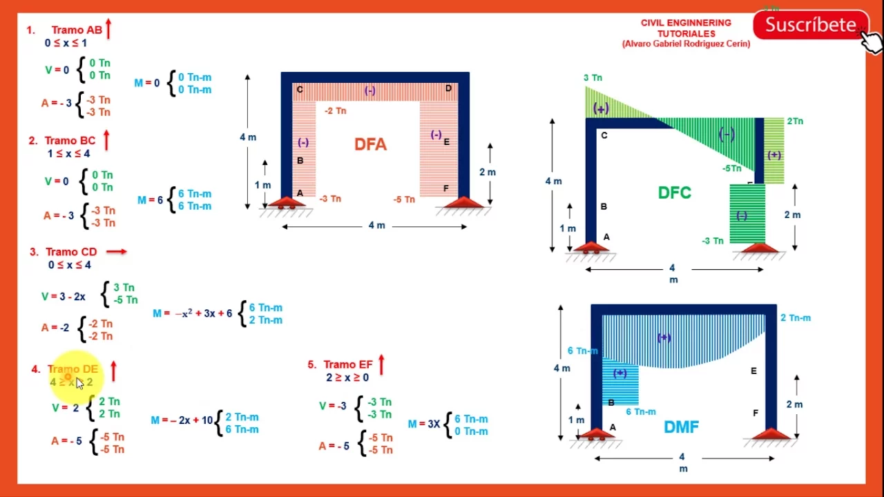
PÓRTICOS - Diagrama de Momento Flector, Fuerza Cortante y Fuerza Axial - Paso a Paso(3/3)
114.8K
This section covers the complete process of drawing the three structural diagrams. For axial force diagrams, negative values (compression) are plotted inside the frame and positive values (tension) outside. For shear force diagrams, negative values go inside and positive values outside, with linear equations producing straight lines and quadratic equations producing curves. For bending moment diagrams, positive values are plotted inside and negative values outside. The instructor emphasizes that moment must be continuous at nodes, and that different load types produce different diagram shapes (linear vs quadratic).
Click to watch →
Axial, Shear force and Bending Moment Diagrams / Dr. Kamal / Civil Engineering Lectures
17.3K
Internal forces in beams include axial force, shear force, and bending moment. Axial force acts parallel to the beam axis (tension positive, compression negative). Shear force acts perpendicular to the beam axis (clockwise rotation positive, counterclockwise negative). Bending moment causes curvature (sagging positive, hogging negative). Standard sign conventions ensure consistency in analysis. Common beam types include simply supported, overhanging, cantilever, propped cantilever, continuous, and fixed beams. For simply supported beams: calculate reactions, draw shear force diagram starting from left support, shear force remains constant between loads and changes at load points. Draw bending moment diagram starting from left support, bending moment equals previous moment plus area under shear force diagram. Maximum bending moment occurs where shear force is zero. For central point load: triangular bending moment diagram. For two point loads: linear segments between loads. For uniformly distributed load: parabolic bending moment diagram. The shape depends on shear force behavior.
Click to watch →

Fundamentals of Mechanics -Topic 5B - Shear Force, Axial Force and Bending Moment Diagrams of Beams
286
This video teaches how to construct shear force, axial force, and bending moment diagrams for beams by sectioning the beam at points where loading conditions change, applying equilibrium conditions (ΣF_x=0, ΣF_y=0, ΣM=0) to each section, and plotting the resulting forces and moments along the beam's length; axial forces are typically zero in standard beams, shear forces remain constant between loads and change at load points, while bending moments vary linearly with constant shear and parabolically with distributed loads, with positive bending moments causing sagging (smile shape) and negative moments causing hogging (frown shape).
Click to watch →
Deep Dive
Basic understanding of portal frame behavior, including the role of columns, rafters, and rigid joints in transferring loads.
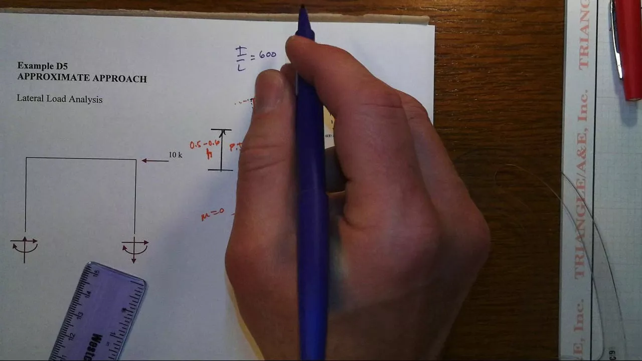
Approximate Frame Analysis with Lateral Load Portal Method
9.2K
A portal frame is a single-story, single-bay moment-resisting frame with rigid joints and fixed ends. Under lateral loading, columns undergo chord rotations while the beam may have no chord rotation if axial elongation is ignored. The frame exhibits reverse curvature behavior where columns bend in opposite directions and the beam curves in an S-shape with inflection points at mid-span. Two extreme cases define behavior: when the beam is flexible, inflection points rise to column tops; when the beam is stiff, inflection points remain at mid-height. For practical analysis, inflection points are typically assumed between 0.5 to 0.6 times column height from the base, with 0.5H being common for approximate analysis.
Click to watch →

Introduction to Structural Engineering - 1+ Hour | Certified Tutorial | Skill-Lync
2K
Portal frames consist of beams connected to columns forming rigid joints. Key principles include: (1) Joint equilibrium requires that bending moments in connected members be equal in magnitude and opposite in sign at the joint; (2) For lateral loads, columns develop bending moments that balance the applied forces; (3) Fixed base conditions develop additional base moments and shear reactions; (4) Pinned bases result in zero moment at the base but develop horizontal reactions; (5) Gravity loads combined with lateral loads create complex interaction patterns requiring superposition of separate load cases. Design involves combining different load combinations per code requirements.
Click to watch →

Portal frame
10.9K
Portal frame construction is a structural method using steel, steel-reinforced precast concrete, or laminated timber with moment-resistant joints between columns and rafters, developed in the 1960s and now the most common enclosure for spans of 20-60m; these rigid joints transfer bending moments from rafters to columns, allowing reduced rafter sizes or increased spans, making it efficient for wide-span buildings like warehouses and barns, typically single-story but usable for low-rise buildings with non-spanning floors, with typical configurations including office space against warehouse walls, cladding with lightweight insulated metal and cavity masonry, and design considerations for roof loads, wind loads, and foundation bracing to prevent instability from the 'pack of cards effect' where non-rigid joints cause outward movement and loss of strength.
Click to watch →

Components of Pre Engineering Building | PEB Building | Steel Structures | PEB Structures
123.8K
Pre-engineered building frames consist of primary structural components including columns (vertical members) and rafters (horizontal members). Columns transfer vertical loads from the roof and floor systems to the foundation through anchor bolt systems with base plates. Rafters support roof loads and transfer them to columns. The foundation connection involves placing mini-columns on the foundation, inserting anchor bolts through base plates, threading nuts onto bolts, and securing the column I-section. Grouting completes the connection. These primary components form the main skeleton of the pre-engineered building system, fabricated in factories based on bending moment diagrams designed for industrial applications like factories and stadiums.
Click to watch →

How does a portal frame work?
607
A portal frame is a structural system consisting of vertical columns connected to horizontal rafters at their apex, forming a rigid triangular frame that resists lateral loads such as wind through moment transfer and axial force distribution; when wind blows against one side of the building, it creates bending moments in the roof trusses that are transferred to the ground through axial forces in the side bracing members, making portal frames particularly effective for resisting lateral loads in one direction while roof trusses handle loads in the perpendicular direction.
Click to watch →
Deep Dive
Concepts of load distribution, specifically how uniformly distributed loads (UDL) and point loads act on horizontal and vertical members.

EQUILIBRIUM|LECTURE 01|TYPES OF SUPPORT AND TYPES OF LOADS|ENGINEERING MECHANICS|PRADEEP GIRI SIR
199.8K
A uniformly distributed load (UDL) is a type of loading that acts evenly across a length of a structural member, such as a beam. It is denoted by 'w' (load per unit length) and is represented graphically as a series of parallel lines or arrows along the length of the member. To convert a UDL to a point load for analysis, multiply the intensity (w) by the length (L) over which it acts: Total Load = w × L. The equivalent point load acts at the midpoint (L/2) of the distributed load span.
Click to watch →

SFD and BMD For Different Type of Loadings -2 | L 35 | Strength of Material |GATE 2022 (ME/XE/CE/PI)
9.2K
This section covers point load and uniformly distributed load (UDL) analysis in structural analysis. Point load is a concentrated load that acts at a single point on a structure, with total load denoted as W. When a load is concentrated at a single point, maximum stress develops at that point. UDL is a load distributed uniformly along the entire length of a beam, calculated as W = w × L, where w is load per unit length and L is total length. The load acts at the center of the beam. UDL is represented as a rectangular load distribution extending from one end to the other. The instructor demonstrates how to represent UDL on beams and calculate total loads for various scenarios.
Click to watch →
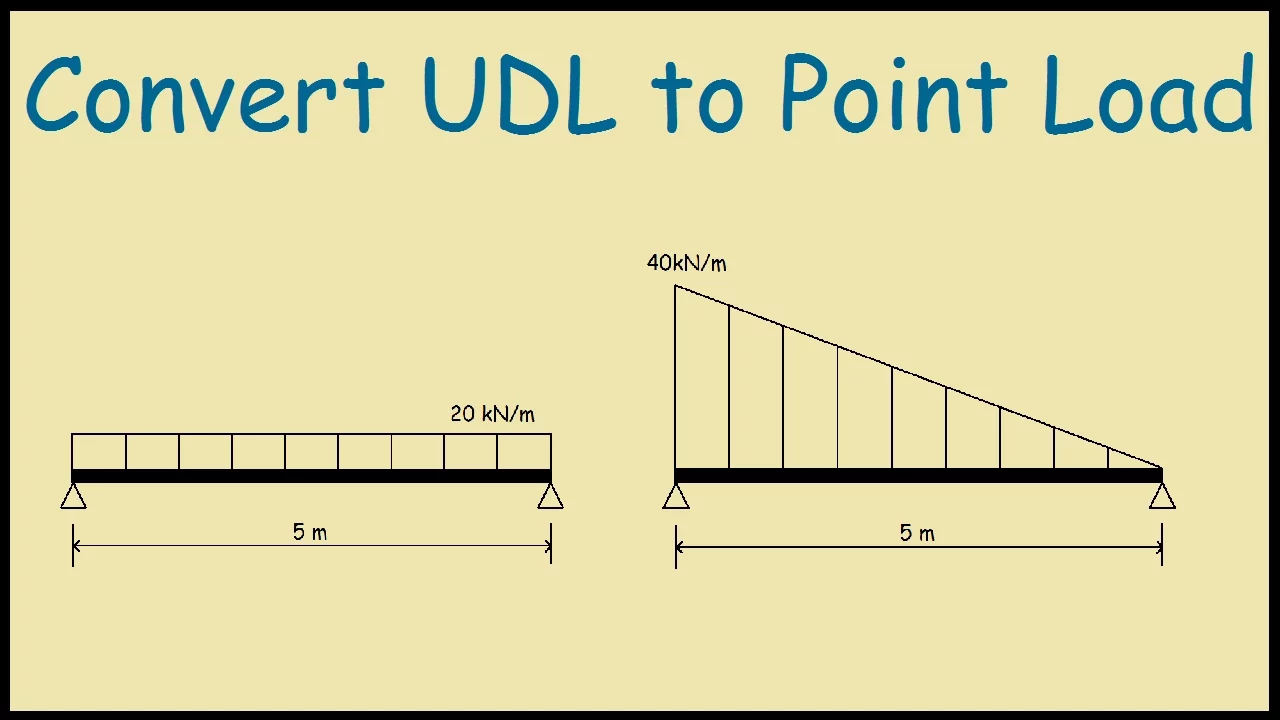
How to convert a UDL to Point Load
151.3K
To convert a uniformly distributed load (UDL) to an equivalent point load, calculate the total force by multiplying the load intensity by the length (area of the load distribution), and locate the point load at the centroid of the distributed load; for a rectangular UDL, the centroid is at the midpoint, while for a triangular UDL, the centroid is located one-third from the heavy side.
Click to watch →

🔥17 Engineering Mechanics UPBTE 2nd Semester Common For All Branch आरम्भ बैच 2.0 New Syllabus || JEC
297
Two primary types of loading act on structural members: (1) Point Load - a concentrated force acting at a single specific location on the structure, such as a weight hanging from a single point; (2) Uniformly Distributed Load (UDL) - a load spread evenly across a length of the member, such as the self-weight of a beam. To analyze structures, UDLs must be converted to equivalent point loads by multiplying the UDL value by the length over which it acts, with the resulting point load applied at the midpoint of that length.
Click to watch →

Types of Loads, Beams and Supports
69.2K
In structural engineering, beams are structural members with length much greater than their cross-sectional area, designed to support loads. There are four main types of supports: Simple Support (provides only vertical reaction), Roller Support (provides only vertical reaction but allows horizontal sliding), Hinged Support (provides both vertical and horizontal reactions but allows rotation), and Fixed Support (provides vertical reaction, horizontal reaction, and resisting moment preventing both translation and rotation). Beams are classified into four types based on support configuration: Simply Supported Beam (supports at both ends), Overhanging Beam (one support at end and another in between), Cantilever Beam (fixed at one end with free end), and Continuous Beam (more than two supports). The three main types of loads applied on beams are: Point Load (concentrated at a single point), Uniformly Distributed Load (UDL - constant load over a length), and Uniformly Varying Load (UVL - load varying linearly from zero to maximum).
Click to watch →
Deep Dive
Knowledge of structural determinacy and indeterminacy, as portal frames are typically statically indeterminate structures.
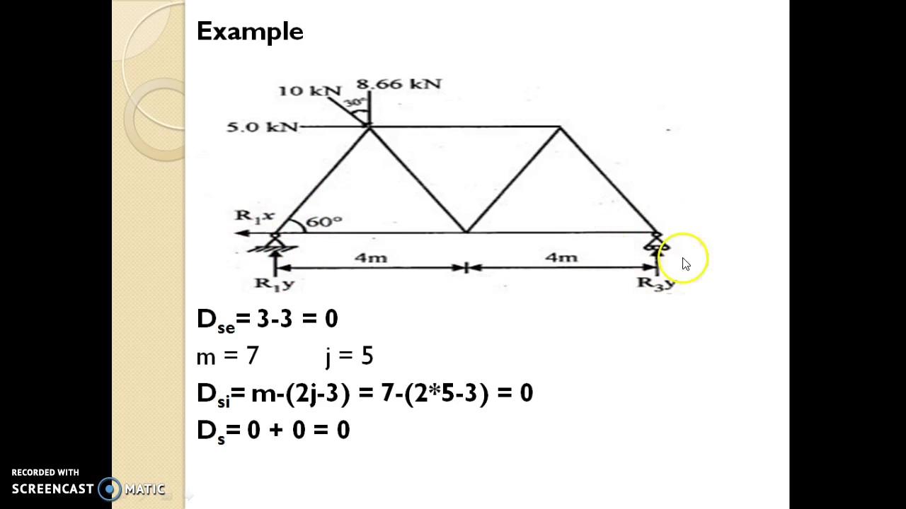
static indeterminacy of beams, truss, portal frames
35.7K
Static indeterminacy occurs when the number of unknown reactions or internal forces exceeds the number of available equilibrium equations (ΣFx=0, ΣFy=0, ΣMz=0). The degree of redundancy (DS) is calculated as DS = DSe + DSi, where DSe = R - S (external reactions minus equilibrium equations) and DSi varies by structure type: for beams DSi = 0, for trusses DSi = M - 2J - 3, and for portal frames DSi = 3C (where C is the number of rigid closed loops).
Click to watch →

GRADOS DE INDETERMINACIÓN, GRADOS DE LIBERTAD EN PÓRTICOS (3D) - EXPLICACIÓN PASO A PASO Y FÁCIL! 💪😜
640
For a 3D portal frame with fixed supports, the total degree of static indeterminacy equals the sum of external indeterminacy (reactions minus equilibrium equations) and internal indeterminacy (6 times elements minus 6 times joints plus equilibrium equations), while the degree of freedom equals 6 times joints minus total reactions; for a structure with 4 fixed supports (24 reactions), 8 elements, and 6 joints, the total indeterminacy is 24 and degree of freedom is also 24.
Click to watch →

structural analysis | DAY 02 |CIVIL ENGINEERING | FREE CLASS | KARPOM TAMIZHA ACADEMY
6.4K
Internal static indeterminacy varies by structural type. For plane frames, DSi = 3 × C, where C is the number of closed boxes. Each closed loop adds three degrees of internal indeterminacy. For example, a portal frame with one closed box has DSi = 3. For beams, DSi is always zero because they are pin-jointed with axial force transfer only. Portal frames combine these principles: DS = DSE + DSi - releases. A frame with 6 unknowns, 3 equilibrium equations, 1 closed box (DSi=3), and 1 internal hinge (release=1) has DS = (6-3) + 3 - 1 = 5. This distinction is critical for exam preparation in engineering services and competitive exams.
Click to watch →

MÉTODO DAS FORÇAS PÓRTICO HIPERESTÁTICO DIAGRAMAS DE ESFORÇOS NORMAL, CORTANTE E MOMENTO FLETOR.
13.9K
This segment introduces the analysis of a portal frame (Pórtico hiperestático) using the method of forces. The instructor explains that the structure has two second-order supports (apoios de segundo gênero), each providing two reactions (vertical and horizontal), resulting in four unknown reactions. The degree of static indeterminacy is calculated as I = number of unknown reactions - number of equilibrium equations = 4 - 3 = 1. This means the structure is statically indeterminate to the first degree, requiring one additional condition to solve. The instructor identifies the three equilibrium equations: sum of forces in X, sum of forces in Y, and sum of moments equal to zero.
Click to watch →

KWA AE | ASSISTANT ENGINEER| STRUCTURAL ANALYSIS | LEARN THROUGH QUESTIONS PART 1 | KERALA PSC
2.1K
Hinges reduce static indeterminacy by providing rotational degrees of freedom. A structure is statically indeterminate when equilibrium equations alone cannot determine all support reactions. Statically determinate beams allow complete analysis using only equilibrium equations. Space frames have 6 equilibrium equations (3 forces + 3 moments), while planar frames have 3. The static indeterminacy formula for frames is d = m + r - 3j, where m is members, r is reactions, and j is joints. Statically indeterminate structures have more constraints than necessary for stability.
Click to watch →
Prerequisite Knowledge
- Concept 01Fundamentals of structural mechanics, including the concepts of bending moments, shear forces, and axial force diagrams.
- Concept 02Basic understanding of portal frame behavior, including the role of columns, rafters, and rigid joints in transferring loads.
- Concept 03Concepts of load distribution, specifically how uniformly distributed loads (UDL) and point loads act on horizontal and vertical members.
- Concept 04Knowledge of structural determinacy and indeterminacy, as portal frames are typically statically indeterminate structures.
Subsequent Learning
- Step 01Analysis of portal frames under lateral loading conditions, such as wind or seismic forces (sway analysis).
- Step 02Design of frame members and connections (bolted or welded joints) according to regional structural design codes (e.g., Eurocodes, AISC).
- Step 03Advanced structural modeling, including multi-story, multi-bay frames, and 3D frame analysis.
- Step 04Introduction to plastic analysis and limit state design of portal frames to understand failure mechanisms.
Frame Modeling
Frame Modeling
0:00Playing Section
- 1
Demonstrates structural analysis of a frame using 2D software.
- 2
Focuses on core modeling workflow and key analysis steps.
Limitations of Linear Elastic 2D Analysis vs. Second-Order Plastic Design
While 2D linear elastic frame analysis software offers an accessible starting point for students, it introduces significant simplifications that can be dangerous in real-world engineering. First, 2D models neglect critical out-of-plane behaviors, such as lateral-torsional buckling and triaxial stresses. Second, linear elastic analysis assumes materials behave elastically indefinitely and ignores geometric non-linearities. Real steel portal frames are highly susceptible to buckling and are typically designed using plastic analysis, which accounts for plastic hinge formation and moment redistribution at ultimate limit states. Furthermore, standard linear 2D solvers omit second-order effects (P-Delta), where structural deformations amplify internal forces under load. Relying solely on basic 2D linear software can lead to unsafe designs; students must complement these tools with non-linear 3D analysis and physical validation.
Deep Dive
Analysis of portal frames under lateral loading conditions, such as wind or seismic forces (sway analysis).

Problem 11 : Kanis Method - Sway Analysis of Portal Frame
107
Sway analysis in frames considers lateral displacement contributions in addition to rotation contributions. A frame may undergo lateral sway due to asymmetric framing, asymmetric support conditions, or asymmetric loading. When a lateral load is applied, additional moments develop at the top and bottom of columns but not in beams. The displacement contributions are calculated using the formula: h = -ΣM_dash_T + ΣM_dash_B / H. The displacement factor (U_dash) is calculated as -1.5 × K / ΣK. For combined vertical and horizontal loading, displacement contributions use: M_double_dash = U_dash × (SR × HS / 3 + ΣM_dash_T + ΣM_dash_B). Kani's method for sway analysis involves four steps: calculating fixed end moments, determining stiffness and rotation contributions, calculating displacement factors and contributions, and using iteration to find final end moments.
Click to watch →

Portal Frame with Sway | L - 7 | Moment Distribution Method | Abhishek Sir
16.2K
In portal frame analysis with sway, when both the structure and loading are symmetric, the sway occurs in a specific direction determined by the asymmetry of the structure or loading; the moment distribution method is applied by analyzing only half the structure using mirror image technique, calculating distribution factors, and balancing moments at joints to determine the final end moments and reactions.
Click to watch →

08-Portal frame A,B | Structural Analysis | Eng-Tuqa
283
This comprehensive section covers the Portal Frame Method for analyzing structural frames under lateral loads (wind, seismic, soil pressure). The method requires equal column cross-sections and involves analyzing frame deformation (delta) at each joint to calculate moments, shears, and normal forces. The video explains that lateral loads cause horizontal deformation requiring specialized analytical approaches. Different variations are covered: equal spans, unequal spans, unequal columns, and combinations thereof. The key principle is that when lateral loads are applied, the frame deforms proportionally, with moments at column midpoints being zero and moments at joints being equal in magnitude but opposite in direction.
Click to watch →

Slope Deflection Method Introduction to Sway Type of Portal Frame and Shear Equilibrium equation
242
A sway portal frame is a structural system that permits horizontal displacement (lateral movement) when subjected to lateral loads. This displacement, denoted by Delta (Δ), is called the sway coefficient. Lateral loads occur primarily due to wind pressure and earthquake effects, causing the frame to deflect in the direction of the applied force. The frame has distinct windward and leeward sides relative to the load direction. The center of gravity (CG) of the frame determines which columns experience tension and which experience compression - columns on one side of the CG undergo tensile loading while those on the opposite side undergo compressive loading.
Click to watch →

Design of Steel Structure Plastic Analysis | Part -7 | For GATE/ESE/SSCJE/All State AE/JE Exams.
1.9K
This section explains the sway mechanism in portal frames. When horizontal load is applied, the portal frame can sway to either left or right. This is an independent mechanism. For a portal frame with horizontal load, the degree of indeterminacy (DS) is 3. Four plastic hinges are required for mechanism development. The instructor demonstrates how horizontal loading causes the frame to sway, with plastic hinges forming at the fixed end, rigid joints, and point load locations.
Click to watch →
Deep Dive
Design of frame members and connections (bolted or welded joints) according to regional structural design codes (e.g., Eurocodes, AISC).

17 How to design Steel Connections and Joints – Lecture | Eurocode 3 Steel Design series
17.3K
Steel connections and joints constitute approximately 50% of frame costs and are critical to structural integrity, requiring proper design according to Eurocode 3 Part 1-8. Connections are defined as locations where two or more elements meet, while joints are zones where multiple members interconnect. Simple joints allow rotation and transfer only shear force, rigid joints transfer moments and require columns to be designed as beam-columns, and semi-rigid joints fall between these extremes. Bolted connections use standard M20 grade 8.8 bolts with 22mm holes, where bolt shear failure (catastrophic) should be avoided in favor of gradual plate bearing failure. Design requires checking bolt shear, plate bearing, and block tearing failure modes, with minimum end distances of 1.2d and pitches of 2.2d and 2.4d. Welded joints use simplified design with effective throat thickness and design shear strength based on minimum ultimate tensile strength of connected parts.
Click to watch →

Design of Steel Frames Workflow: Members & Connections as per Eurocode EN1993 using Autodesk Robot
13K
Configure Robot for Eurocode design by modifying job preferences to select appropriate databases and codes: materials (EN 1993 for steel), steel sections database, bolt databases (regionally available), and design codes for steel, connections, reinforced concrete, geotech, and load combinations. Verify Eurocode selection for all categories, choosing between general Eurocode or national annexes. Apply member types with proper properties: configure lateral buckling lengths for beams (upper flange ~0.1L for continuous bracing, lower flange full span), and enable automatic K-factor calculation for columns based on beam-column stiffness interactions. Define supports (pinned, fixed, semi-rigid) and apply dead, live, and wind loads. Create multiple frame copies to compare support conditions. Generate automatic load combinations through Loads > Automatic Combinations, verifying Eurocode selection. Create member groups for efficient design: group columns and beams separately for each frame type. Execute steel member design through Design > Steel Member Design, specifying ULS combination. Interpret results showing controlling members, best sections, and verification status. Address practical considerations like maintaining consistent section sizes between beams and columns for simplified connections.
Click to watch →

The correct way to make welded splice joints in chassis members
294.4K
According to the AISC 360 design code written by the American Institute of Steel Construction (the most widely used steel structure design code worldwide), for competently formed butt welds using correct filler material or electrode for tension, compression, and shear cases, the strength of the joint is determined by the strength of the base metal, not the joint configuration itself. This means that concerns about joint angle having no effect on strength are unfounded when proper welding procedures are followed.
Click to watch →

Design of Bolted Beam Framed Connections in Steel Structures| Hindi | Part-1 | DSS |
23.7K
Framed connections in steel structures are joints that connect beams to columns, where the beam is connected to the column through flanges and web, with the flange plates typically welded or bolted to the column flanges and the web plate welded to the column web, creating a rigid structural connection that transfers loads between structural members.
Click to watch →

Bolts | Welding connection | civil engineering competitive exam #civilbooster #civilengineers
163
This comprehensive section covers structural connection design for civil engineering. Bolted connections use bolts in place of rivets for non-vibrating structures, loaded in tension, shear, or both. Three bolt types: Turn and Finish (small, 152.5mm tolerance), Black and Unfinished (hexagonal/square, temporary fasteners, A2 designation), and HSFG (Class 8.8/10.9, medium carbon steel, best for stress reversal). Joint types: Lap Joint (single/double shear, less strength, no cover plate, eccentric) and Butt Joint (single/double cover, stronger, zero eccentricity). Welded joints offer advantages: no holes, faster fabrication, better appearance, more economical, less working space, no noise. Fillet weld specifications: effective throat = 5/8 × minimum plate thickness, minimum weld size 3-8mm based on thickness, returns = 2 × weld size. Combined stresses: normal and shear τ = √(f_a² + 3f_v²) / (√3 × γmw), combined bearing and bending τ = √(f_b² + f_v² + 3q²). Tension member design involves net area calculation (A_net = (b - d) × t + Σ(d_i²/4g_i)), slenderness ratio limits (400 permanent, 350 with reversal, 180 other), and failure modes: net section rupture (Td = 9A_eFy/γmo), gross section yielding (Td = AFy/γmo), and block shear failure.
Click to watch →
Deep Dive
Advanced structural modeling, including multi-story, multi-bay frames, and 3D frame analysis.
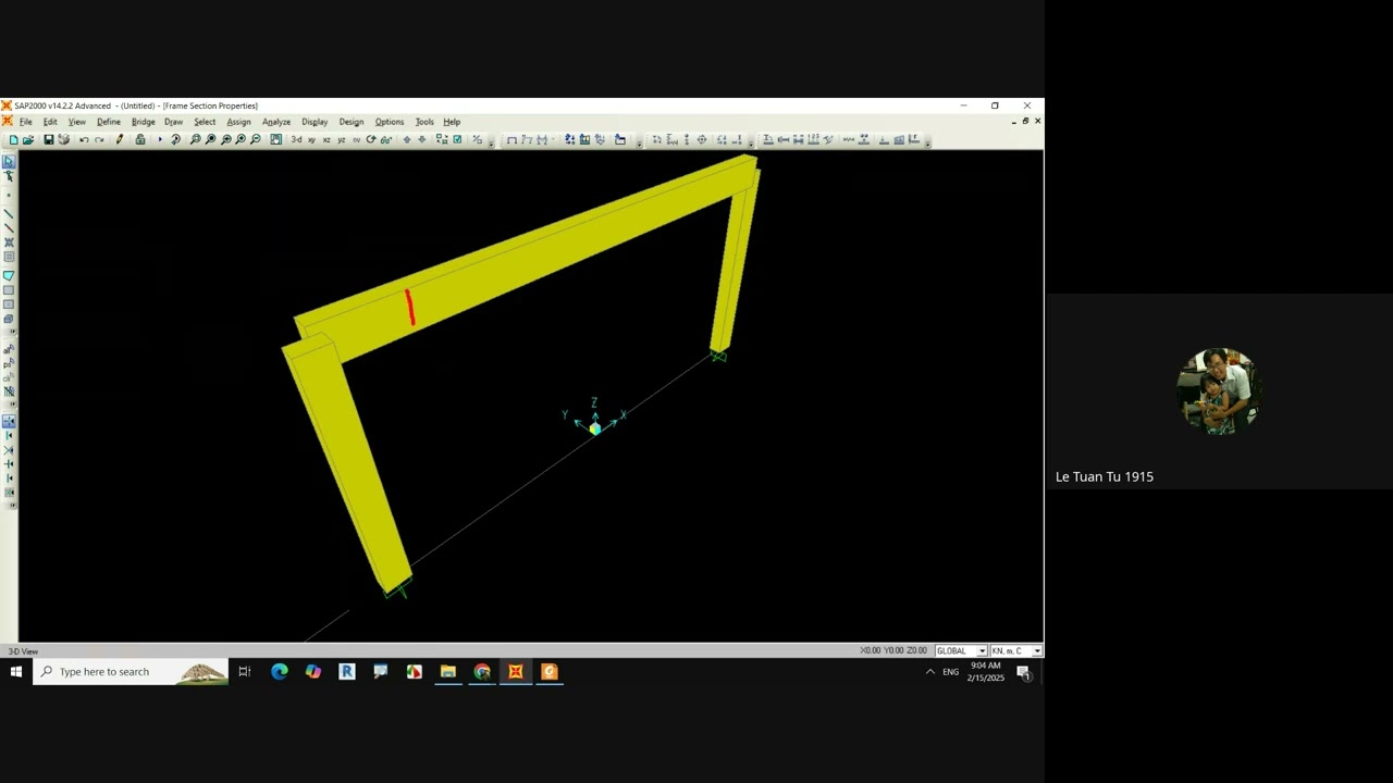
CN332E SAP2000-BUỔI 3-KẾT CẤU KHUNG PHẲNG BTCT
920
This section advances to complex structural analysis techniques and multi-story frame modeling. The instructor explains envelope diagrams that combine all load combinations to show maximum and minimum values at each point, producing two lines for beams (maximum positive and negative moments). The section introduces a 6-story, 3-bay frame model with different floor heights (5m ground floor, 3.5m upper floors) and bay dimensions (3.5m and 7.7m). The instructor demonstrates deleting unnecessary members, setting boundary conditions (fixed supports at base), and systematic member naming conventions (C for columns, B for beams, with floor numbers and Z-axis before X-axis). The section covers applying loads to multiple members simultaneously, different types of live loads (continuous and alternating spans), and wind load distribution to windward and leeward faces for different wind directions.
Click to watch →

Plastic Analysis: CVL 756: Lecture 11
362
This lecture from IIT Delhi's Advanced Structural Analysis course (CVL 756) explains how to extend plastic analysis methods to complex multistory and multi-bay frames by identifying independent mechanisms (beam mechanisms, sway mechanisms, and joint mechanisms) and systematically combining them to find the critical collapse mechanism that satisfies both yield and equilibrium criteria. The computational effort increases significantly with more stories and bays, making plastic analysis more challenging for complex structures compared to simpler single-story or single-bay frames.
Click to watch →

Design & Analysis of A Medium-Rise Building - Part 1 of 6
32.4K
Advanced structural modeling involves defining section properties with concrete compressive strength of 3,000 psi and reinforcement yield strengths of 415 MPa (main bars) and 275 MPa (stirrups). Section modifiers adjust stiffness according to NSCP provisions: 0.35Ig for beams and 0.25Ig for slabs. Reinforcement cover calculations ensure proper bond development with values around 53mm for beams. Slab modeling uses membrane type for in-plane force resistance with 125mm thickness. Efficient multi-story generation employs replication techniques copying ground floor elements along grid axes at specified intervals (3m and 2.5m). Frame division at gridline intersections creates proper joints for accurate load transfer analysis. This systematic approach combines section definition, slab modeling, and replication to create comprehensive structural models ready for detailed analysis and design verification.
Click to watch →

Direct Analysis Method Applications and Examples
35K
For multi-story buildings with brace frames in one direction and moment frames in another: (1) Include all floors, roof, brace frames, moment frames, and gravity columns in the model; (2) Account for leaning columns in each direction; (3) Apply appropriate load factors; (4) Calculate notional loads at each elevated level; (5) Mesh columns into four segments; (6) Define stiffness reduction method; (7) Run second-order analysis; (8) Check drift ratios; (9) Optimize member sizes; (10) Perform final strength check with reduced stiffness.
Click to watch →

simple SSI model construction in ABAQUS
18K
The structural frame is assembled by rotating columns to be parallel to the Z-direction using 90-degree rotations around the X-axis. Beams are moved to connect to columns and copied using linear patterns. Additional beams are rotated around the Z-direction to complete the frame configuration. Three stories are created using linear pattern with 4-meter vertical spacing between floors.
Click to watch →
Deep Dive
Introduction to plastic analysis and limit state design of portal frames to understand failure mechanisms.

SSC JE 2024 Civil Engineering 100 MOST EXPECTED QUESTIONS🤯🔥 | Steel Structures | SSC JE Civil PYQs
14.8K
This section covers plastic analysis of portal frames. For portal frames with plastic hinges at both ends and mid-span, collapse load is calculated using kinematic method. External work equals internal work: W × (L/2) × θ = 2Mpl × θ, so W = 4Mpl/L. Combined mechanism analysis considers simultaneous hinge formation on both sides. External work = W × L × θ, Internal work = 4Mpl × θ, so W = 4Mpl/L. Combined mechanism typically gives minimum collapse load.
Click to watch →

Rigid Plastic Analysis of Portal Frames
1.7K
In rigid plastic analysis of portal frames, plastic hinges form at the weaker sections (columns with moment capacity μ versus beam with 2μ), and the collapse load is determined by equating external work to internal work; for combined mechanisms, the true collapse load of 5μ/l is obtained by superposing the vertical beam mechanism (6μ/l) and sway mechanism (6.67μ/l), which is lower than either individual mechanism.
Click to watch →
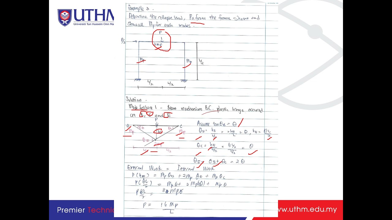
Chapter 7 Plastic Analysis of Frame
732
Plastic analysis of portal frames uses virtual work methods to determine collapse loads. Frames have two mechanism categories: free mechanisms (can move without restraint) and combined mechanisms (beam + sway). Three mechanism types exist: beam mechanism (load on top causes hinges), sway mechanism (horizontal force causes frame sway), and combined mechanism (combination of both). The number of free mechanisms is calculated using me = n - d, where n is total plastic hinges and d is redundant reactions (d = r - 3). For a frame with 4 hinges and 1 redundant, me = 3 mechanisms. The virtual work method applies: External Work = Internal Work. For beam mechanisms: External work = (1/2) × length × height × θ, Internal work = sum of (Mp × θ). For sway mechanisms: External work = Force × displacement, Internal work = sum of (Mp × θ). For combined mechanisms: combine both approaches. The maximum collapse load is the smallest value among all failure modes.
Click to watch →

Plastic Analysis Problem No - 26 ( Finding Collapse Load in a Frame )
17.1K
In plastic analysis of portal frames, the collapse load is determined by analyzing different mechanisms (beam mechanism, sway mechanism, and combined mechanism) and selecting the minimum value; for a portal frame with central point load 2W and nodal point load W, the collapse load is found to be 4 times the plastic moment of resistance divided by the span length (Wc = 4Mp/l).
Click to watch →

Design of Industrial Warehouses | Part 4: Design of Portal Frames
11.8K
Portal frame design encompasses ultimate and serviceability limit states. Ultimate analysis uses elastic methods (permissible beyond yield per Eurocode/American codes) or plastic analysis examining hinge formation at maximum moment locations: rafter haunches for positive moments, column weakest points for negative moments. Haunches increase strength, preventing hinges at rafter ends. Column bases exist on a pinned-fixed spectrum with spring stiffness assumptions (10% for alpha critical, 20% for deflection). Serviceability deflection criteria vary by country: Spain specifies H/150 (53mm for 8m height) for non-fragile elements, France uses L/250. Cross-section classification determines plastic analysis applicability: Class 1 allows rotation beyond plastic moments (with strain hardening), Class 2 drops below plastic moments when over-rotated, Class 3 cannot reach plastic moment due to local buckling, Class 4 cannot reach yield moment. Plastic analysis requires Class 1 sections.
Click to watch →
Frame Modeling
Frame Modeling
0:00- 1
Demonstrates structural analysis of a frame using 2D software.
- 2
Focuses on core modeling workflow and key analysis steps.
Limitations of Linear Elastic 2D Analysis vs. Second-Order Plastic Design
While 2D linear elastic frame analysis software offers an accessible starting point for students, it introduces significant simplifications that can be dangerous in real-world engineering. First, 2D models neglect critical out-of-plane behaviors, such as lateral-torsional buckling and triaxial stresses. Second, linear elastic analysis assumes materials behave elastically indefinitely and ignores geometric non-linearities. Real steel portal frames are highly susceptible to buckling and are typically designed using plastic analysis, which accounts for plastic hinge formation and moment redistribution at ultimate limit states. Furthermore, standard linear 2D solvers omit second-order effects (P-Delta), where structural deformations amplify internal forces under load. Relying solely on basic 2D linear software can lead to unsafe designs; students must complement these tools with non-linear 3D analysis and physical validation.
Fundamentals of structural mechanics, including the concepts of bending moments, shear forces, and axial force diagrams.
Basic understanding of portal frame behavior, including the role of columns, rafters, and rigid joints in transferring loads.
Concepts of load distribution, specifically how uniformly distributed loads (UDL) and point loads act on horizontal and vertical members.
Knowledge of structural determinacy and indeterminacy, as portal frames are typically statically indeterminate structures.
Analysis of portal frames under lateral loading conditions, such as wind or seismic forces (sway analysis).
Design of frame members and connections (bolted or welded joints) according to regional structural design codes (e.g., Eurocodes, AISC).
Advanced structural modeling, including multi-story, multi-bay frames, and 3D frame analysis.
Introduction to plastic analysis and limit state design of portal frames to understand failure mechanisms.
8.1K views32likes3:44@engissolOriginal Release: 2020-03-25
STRUCTURAL ANALYSIS OF A FRAME USING 2D FRAME ANALYSIS SOFTWARE
Up Next

14:48
Buckling Explained: Euler's Formula & Column Design
@TheEfficientEngineer
1.1M views•2021-08-17

30:32
Ultrasonic Transducers: Resonant Frequency Measurement and Horn Design
@imajeenyus42
229.9K views•2017-02-22

54:16
Polymer Environmental Degradation: Mechanisms & Stabilization
@iit
1.8K views•2012-07-10

33:39
How a Student's Question Saved a NYC Skyscraper from Collapse
@veritasium
22.8M views•2025-04-26
Related Study Plans & Knowledge Roadmaps
Structured learning paths in Engineering
engineering
Building Acoustic Levitators: Physics & Arduino
01The Physics of Sound and Standing Waves
02Piezoelectric Transducers and H-Bridge Drivers
03Arduino Programming: Generating 40 kHz Signals
+ 2 more learning modules
14h5 modules
Explore Roadmap
engineering
Building Peltier Cloud Chambers: Particle Tracks
01Cosmic Rays & Cloud Chamber Physics
02Thermoelectric Cooling (TEC) Fundamentals
03Custom Liquid-Cooling Loop Design
+ 2 more learning modules
18h5 modules
Explore Roadmap
engineering
Yagi-Uda Antennas: Modeling, Build & VNA Test
01Introduction to RF and Antenna Fundamentals
02Yagi-Uda Antenna Design Principles
03Antenna Modeling and Simulation in 4NEC2
+ 2 more learning modules
18h5 modules
Explore Roadmap
engineering
ECG Monitor Design: Op-Amps, Filters & Noise
01Electronics & Breadboard Basics
02Op-Amps and Instrumentation Amplifiers
03Bioelectricity and ECG Fundamentals
+ 2 more learning modules
18h5 modules
Explore Roadmap