









![The Greatest Thinkers | Norbert Wiener [1981]](https://i.ytimg.com/vi_webp/YrdgPNe8KNA/maxresdefault.webp)
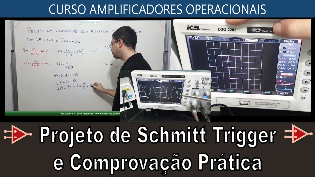


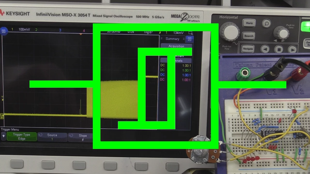




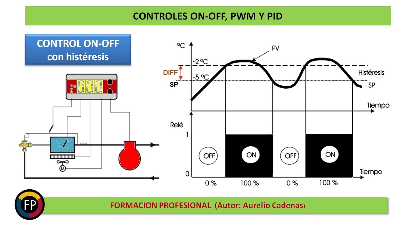
Hysteresis is a control technique that uses two thresholds (high and low) instead of a single threshold to prevent rapid switching caused by noisy input signals; when the input crosses the high threshold, the output turns on, and it only turns off when the input drops below the lower threshold, ensuring stable operation even with input noise as long as the noise level is less than the hysteresis value (the difference between the two thresholds).
Understanding Hysteresis in Control Systems | Schmitt Triggers Explained
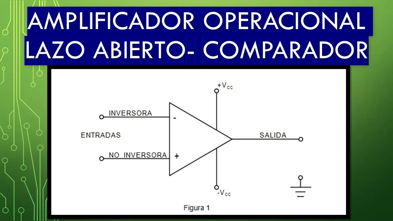
Added:Basic Operational Amplifier (Op-Amp) theory, specifically how they function as open-loop voltage comparators.
The concept of On-Off (Bang-Bang) control systems and how they regulate physical processes like temperature or pressure.
An understanding of electrical signal noise and how high-frequency fluctuations affect analog sensor readings.
The fundamental difference between positive feedback (which destabilizes or accelerates a state change) and negative feedback (which stabilizes a system).
Mathematical calculation and circuit design of Schmitt triggers, including determining resistor values for specific upper and lower threshold voltages.
Practical applications of hysteresis in digital electronics, such as switch debouncing and signal conditioning for microcontrollers.
Studying magnetic hysteresis (B-H curves) and its impact on transformers, inductors, and magnetic storage media.
Advanced control methodologies, such as Proportional-Integral-Derivative (PID) control, which offer smoother alternatives to on-off control.
398 views10likes9:25Original Release: 2020-10-04
[Music] this video is about hysteresis it corresponds to section 16.1 of applied analog electronics now hysteresis is a tool that we use for solving a particular control problem and this control problem comes up a lot in many different applications and it's the one of having an on off control that's controlled by a single continuous input example this is the thermostat that's used for controlling a heater or an air conditioner or a refrigerator freezer almost all those devices have a simple on or off control for whether they're heating for the furnace or cooling for an air conditioner refrigerator and the input is a temperature measurement which is not a simple it's hotter it's cold it's a continuous value what is the problem that we address here well let's take a look at a simple solution and see where it runs into trouble okay simple solution we have got an input and an output for our control device and the input is going to be something like temperature and let's say we're doing a freezer cooler or something like that so when it's already cold enough we just leave the thing off but then when it gets too hot we wanna turn it on okay and so there is a particular voltage here or temperature particular input value of whatever the input is and which we make a transition from off to on and so that's that threshold makes this a single threshold system and it's a very simple system you just compare what your input is to what your threshold value is to determine whether you turn on or turn off what's the problem well what happens if the input measurement is noisy well here's an example the orange is yellow there is an input value with quite a bit of noise on it and i've put a single threshold here at 1.5 volts or 1.48 volts i guess and if you look at the output there in blue it doesn't turn on or off cleanly as the signal crosses the threshold the noise makes it cross back in fact it may make it cross back several times and as a result it flickers on and off the output well a lot of the devices that we want to control with simple on off controls are ones that don't tolerate the sort of flickering on and off you know you're trying to light a flame you don't want to say oh turn the flame on turn the flame off turn flame on turn the flame off because you may not be able to manipulate your valves quickly enough to do that you may end up with all kinds of damage to things because they're not designed to be moved to change that often or that frequently so it's not a desirable solution if we're just looking at purely electrical stuff why don't we want to count events and so here if we're trying to count well how many times did this thing go low well do we really want to count this as six or seven or did it go to once load just once here and there was some noise on it so this is noisy output as a result of noisy input is not really a desirable property so let's look at a possible solution to that what we can do is to say well if we can remember what state we're in whether we're on or off we can say hey if we're on let's require the value to be a little bit lower before we change our mind and turn off again and if we're off let's require that it be a little bit higher before we turn on so we now have two thresholds a low threshold and a high threshold and if we're between the two thresholds then we're just staying in whatever state we're in we're not changing our mind and what that means is if we've got some noise well once we've crossed this threshold and turned off we can have quite a bit of noise flickering back and forth here without turning on we have to get all the way up to here before we turn on and then once we've turned on again we can flicker back and forth here without turning off as long as our noise is less than this difference between the two inputs and that's often referred to as the hysteresis value or if it's a voltage the hysteresis voltage and that's the difference between these two things as long as your noise is less than that you're not going to get sort of the double transitions you'll only get transitions when you actually move all the way past one of these let's take a look at what that looks like with the same noisy signal we looked at before okay so this is the same noisy signal but i've got two thresholds at 1.1 volts and 1.9 volts and you can see that the blue signal is not making multiple transitions because i had the sort of smooth curves like i drew in the uh on the paper there's a little bit of a glitch just a small one at the at the transitions and that was easily removed by just running the thing through ordinary digital logic digital logic would not see that tiny glitch as being a change in value it's just a one until you get all the way down to the zero then it just stays zero all the way until you make the transition up to the one so those tiny glitches are easy to clean up and basically don't affect anything so here we've got something that makes just a single transition down to low single transition up to high if we were counting how often we were low they would just see this as a single event um if you were doing something where you're turning uh motor refrigerator or heater on or off we'd only have a single hey we've got to turn it off for a bit and now we turn it back on again everything is working the way we would want it to as long as the noise is less than that difference between the two thresholds once your noise gets bigger than the difference between two thresholds then you can get the flickering back and forth again okay so what else do we care about on this well one thing is when we're doing this we really don't want that sort of smooth curve that i drew here it'd be nice to have a very sharp transition where it just goes hey i go almost almost no voltage change at the input to go from zero to one on the output and that's done by using digital logic in fact the signal the circuits we usually use for doing these things are called schmidt triggers and a schmitt trigger is got a nice digital output and it makes a very fast very sharp transition so it's used very frequently for cleaning up signals to turn them into digital signals it's even used for cleaning up digital signals that come in because if noise gets added to a digital signal you still want to have a clean interpretation of it as a zero or one so essentially all the digital inputs on things like the team clc microcontroller board they all have schmitt triggers on the inputs just so that it interprets whatever is coming in as a clean digital signal there's also another thing that i should tell you about and that is that there's a slight variant on what i've been showing you for hysteresis everything i've been showing you so far had low input produces low output high input produces high output but you can turn that around the other way you can have something that has a high output for a low input and a low output for a high input and the hysteresis can still be done and this is an inverting schmitt trigger or as it's sometimes written written a schmidt trigger inverter and we'll be using one of these um the 74 hc14n is a schmitt trigger inverter and that's probably about all you really need to know about for hysteresis right now in a subsequent video we'll look at some circuits that use hysteresis in some somewhat surprising ways [Music] you
Up Next

6:48
Time-Controlled Switch with ESP32 Web Server and DS3231 RTC
@ElectroniClinic
3K views•2024-06-02

30:32
Ultrasonic Transducers: Resonant Frequency Measurement and Horn Design
@imajeenyus42
229.9K views•2017-02-22

54:16
Polymer Environmental Degradation: Mechanisms & Stabilization
@iit
1.8K views•2012-07-10

33:39
How a Student's Question Saved a NYC Skyscraper from Collapse
@veritasium
22.8M views•2025-04-26
Related Study Plans & Knowledge Roadmaps
Structured learning paths in Engineering
engineering
Building Acoustic Levitators: Physics & Arduino
01The Physics of Sound and Standing Waves
02Piezoelectric Transducers and H-Bridge Drivers
03Arduino Programming: Generating 40 kHz Signals
+ 2 more learning modules
14h5 modules
Explore Roadmap
engineering
Building Peltier Cloud Chambers: Particle Tracks
01Cosmic Rays & Cloud Chamber Physics
02Thermoelectric Cooling (TEC) Fundamentals
03Custom Liquid-Cooling Loop Design
+ 2 more learning modules
18h5 modules
Explore Roadmap
engineering
Yagi-Uda Antennas: Modeling, Build & VNA Test
01Introduction to RF and Antenna Fundamentals
02Yagi-Uda Antenna Design Principles
03Antenna Modeling and Simulation in 4NEC2
+ 2 more learning modules
18h5 modules
Explore Roadmap
engineering
ECG Monitor Design: Op-Amps, Filters & Noise
01Electronics & Breadboard Basics
02Op-Amps and Instrumentation Amplifiers
03Bioelectricity and ECG Fundamentals
+ 2 more learning modules
18h5 modules
Explore Roadmap