







![Introduccion a C++ [Curso de Programación C++] [1/28]](https://i.ytimg.com/vi_webp/_vzc9pQnpic/maxresdefault.webp)







![ZIEGLER NICHOLS ✅ SEGUNDO Método [Control PID] Parte 2](https://i.ytimg.com/vi_webp/AAaWNNuqpuY/maxresdefault.webp)


![HIL Solutions [EP.6] การประยุกต์ใช้Hardware In Loopในการทดสอบผลิตภัณฑ์โดย อ.ศุภลักษณ์ ศรีตา ม.นเรศวร](https://i.ytimg.com/vi_webp/qPLnL2q_KDw/maxresdefault.webp)

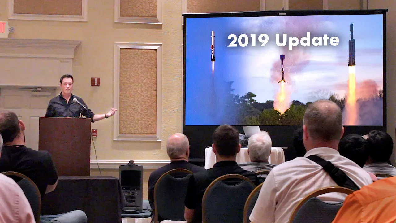
This video provides a comprehensive roadmap for building thrust vector controlled (TVC) model rockets, covering the fundamental concepts of TVC (changing thrust direction to stabilize rockets), practical implementation methods (gimbal mounts, jet vanes, liquid injection, paddle systems), flight computer components (microcontrollers, IMUs, barometers, MOSFETs), and the critical PID control algorithm (proportional-integral-derivative) for maintaining rocket stability. The presenter emphasizes starting small with 500-1000g rockets using cardboard airframes and F motors, implementing a state machine for flight phases, and carefully tuning PID gains for stable flight.
Thrust Vector Control for Model Rockets: A Beginner's Roadmap
Added:Basic Rocketry Physics: Understanding Center of Gravity (CG), Center of Pressure (CP), and aerodynamic stability.
Fundamentals of Microcontrollers: Experience with hardware platforms like Arduino, including reading sensor inputs and outputting PWM signals to servos.
Introductory Programming (C/C++): Familiarity with basic coding structures, logic, and variables used in flight computer software.
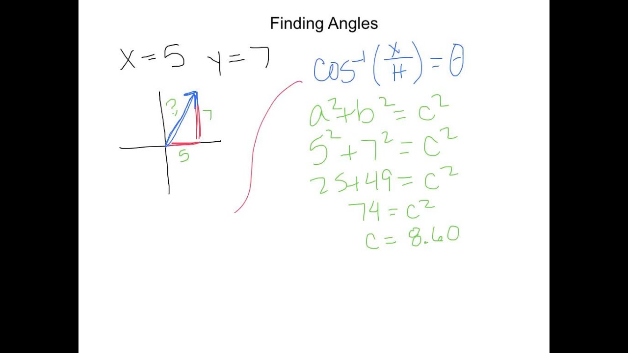
Basic Vector Mathematics and Trigonometry: Comprehending forces, angles, and 3D coordinate systems to understand thrust redirection.
Sensor Fusion and State Estimation: Implementing Kalman Filters to combine accelerometer and gyroscope data for precise attitude estimation.
Advanced PID Tuning and Control Algorithms: Exploring gain scheduling, active roll control, or transitioning to Linear Quadratic Regulators (LQR).
Hardware-in-the-Loop (HIL) Testing: Simulating aerodynamic environments on hardware to test flight computers prior to physical launch.
High-Power Rocketry (HPR) Certification and Safety Regulations: Navigating official guidelines (such as NAR or Tripoli) for launching actively-guided rockets safely and legally.
326.9K views12.7Klikes50:12Original Release: 2020-03-09
my name is Joe Barnard I build model rockets that use active control via thrust vectoring in the last two years I have given presentations at this conference and talked mostly about what I have done and that's cool that's all well and good but at some point like just you just don't need to feed the ego anymore so I figured since they're in like the last year or two there been a couple of projects that have gotten started that are trying to do similar things this is the stuff is really cool and man I I totally love that so there are a bunch of people who are trying to do similar things and I figured if I could lay out some type of road map to give people a sense of like where you can go like hat like if you don't know anything about this and you want to get started what does it sort of look like what does this whole project look like if you want to take it on yourself it's it's a little harder to get to something like that but I wanted to sort of see if I could simplify it a bit so let's get started with the real basics I'm sorry this is cut off here I'm not sure what's going on oh geez is it gonna be okay should we leave it okay so what is the rust effector control is it a thing you can hold can you give it to a friend and you throw it off a cliff no you cannot it is a technique not a physical thing and so it is a technique that we use in the aerospace industry to stabilize craft sometimes they are airplanes fighter jets sometimes they are rockets and so let's just walk over how that works I've got some little animated drawings here here's my bps rocket and when we zoom in on the bottom of it you'll see that we have a thrust vector going down it's just a vector it's an arrow and then we have a reaction force vector going directly upward that's when everything is going well and right on over here when things are going a little sideways we have a thrust vector that's going to the side and what ends up happening is we resolve two force vectors one is going vertical and then we've got a tiny little one going to the side and so when we talk about thrust vector control that little arrow is what we're talking about it's not it's not a it's not a thing you can hold it's not a thing you can give to a friend so that little air is what we're talking about so how do you do it how do you accomplish TVC in any scale what I like to do is gimbal Inge the motor and by that you basically you put the motor on a dual axis hinge so the motor can hinge to the side it can hinge up or down and by that you change the vector of the thrust but you can also do it with the nozzle of the motor this is the Space Shuttle SRB solid rocket booster and this is some sped up footage of it vectoring the nozzle during a ground test these are jet vanes that are used on the v2 rocket and so by putting small fins into the exhaust stream you can deflect them and change which way the exhaust goes this is footage from Copenhagen suborbitals of their jet vane approach it's pretty cool this is pretty incredible footage the other approach you can use is called Li TVC and though the the screen is cut off here this is from the Boston University rocket propulsion group Li TVC stands for liquid injection thrust vector control and by injecting a reactive or inert gas into the exhaust stream you can change the direction of the thrust in a really binary way isn't that crazy and then finally we've got this is the vector Bravo system from Florida Tech and this is a thrust paddle approach where you put small paddles into the exhaust stream in order to deflect the thrust so there the point of all of these things is to just change the direction of your nominal thrust right and I'm being really exhausted with covering all of this stuff but the next question you might have is okay cool so I want to do this on my rocket and I saw that dude who carbonated milk online was able to do it so like I can obviously do it yeah I'm sure you did I'm sure everyone's sorry it's gonna haunt me forever so how do you do it at the model scale well my first advice is to start small I've gotten like a bunch of emails from folks who they have the right intentions and they say hey I really want to try this stuff but I've got an N motor an M motor that I want to work with right and I want to rip on up to 50 K with TVC and how do I put this in like the nicest and most gentle possible way the first time that you try to do something like this the likelihood of it going exactly how you want is somewhat low this one looks okay but so my advice is to start small so that when this happens with an F motor it's a lot more forgiving than with an M motor now I would aim for a vehicle mass of roughly 500 to 1,000 grams just to talk specifics here 500 to 1,000 grams is definitely within the local low-power class of model rockets and that's going to give you a great selection of rocket motors and it's also going to give you a great selection of airframes so sixty six millimeter is a bt eighty seventy four is a three inch tube 98 is a four inch tube these are excellent tubes to work with I recommend going with the cardboard variant you can work on you know fiberglass or carbon fiber or something like that but with these weights and with the motors you have available cardboard is a great option and you're also going to be doing a lot of modifications to the tube so I do recommend starting with that at the very least and then finally I would go for the gimbal mount I'm not trying to tell you what you can and can't do but liquid injection thrust vector control at 500 grams mass is going to be difficult to say the least alright so that's how you can go about it this is the way that I have approached it this is the gimbal mount that I've I've done so you're just gimbley the entire motor I've got two servos here and this has similarities with onions and Shrek in that it works in layers so if we've got we've got the motor mount directly connected to that bottom servo and that works on one axis but then this top servo is sort of the outer layer of the whole gimbal and it gimble's the entire bottom assembly right so we're decoupling these axes but this is by far not the only way you can do it my friend Rob again that's it's cut off a little bit my friend Rob is an actual like orbital launch vehicle engineer down in Cape Canaveral he he really knows what he's doing but he's got a couple of different setups as well so he his thrust vector control approach uses it's not technically linear actuators but it's actually quite close to how you would gimble a liquid engine in that you've got these two orthogonal or two ninety degrees apart rods that come down on the motor he's also got a compliant imbel which once again it's a little hard to see here but it's a compliant gimble means there are no hinges at all it's all rubbery plastic that's that's hinging so you don't get the degradation of any metal from exhaust products of the motor or something like that which is pretty cool he's forty zero systems is really great and then finally this is just a slide from last year's talk I wanted to re-emphasize the importance of iteration here it's gonna be really hard just kind of like the clips that I showed earlier of the failing rec it's gonna be hard to get it right on your first try and so if you're building something like this yourself don't don't get too down on it it's it's going to take a couple of tries to get it right and it certainly has for me and then just this is a small little advertisement but if you want any of these files they are available for download on the BPS website ok next up how do you control this stuff if you've ever flown model planes does anyone here flood model planes cool we got a couple of folks you need a receiver right you need something on the craft that can talk to all of the control surfaces and so we need something like that for a model rocket you have it you could have a pixhawk these are sort of all in one flight control systems you can also have an RG pilot APM all of these are cool options for model airplanes but I don't recommend using them for model rockets what you really want to have is full control over the software that's running on it and full control over the hardware that's going on it and that's going to be the most efficient approach so it's not too hard to do and I wanted to start with a conceptual representation of what you need to do to build your own flight computer I'm going to label this you see you stands for micro and c4 controller U is the sort of subscript for Micro right so in the very center we're going to have something called a micro controller and that's going to run all of our code connected to that we're going to use an inertial measurement unit or IMU for short that has a set of accelerometers and excessive gyroscopes to help us sense our orientation and where we're moving we also need to sense how high above the ground we are and that's going to be done with the barometer you could do that with a lidar and you could do it with a radar too but it's going to be difficult to keep that pointed at the ground to resolve the altitude of your vehicle then we've got the the belle of the ball here the TVC servos this is what it's all about so these are going to connect to your microcontroller as well this is pretty important if they're not connected they don't work so you've got your thrust vector control servos and the microcontroller is going to make send all of the commands to them parachutes are non-negotiable I am speaking to my I'm speaking to my former self here don't skimp on parachutes you need a way to get your vehicle back and you need a way to do it safely and responsibly and if you don't you end up hurting the Hobby because of it so we want to be making sure that we're doing this in a safe way and we can get it back and so the parachutes are going to be controlled by the microcontroller obviously you've got a battery connected to power all of these things and then raise your hand if you've ever been in a field setting up a rocket and something has gone wrong and you have had to search for a dongle and then plug in your laptop and the bright Sun and it has been a nightmare okay well no one's writing to their hand but I'm gonna assume that some of you are familiar with the stress of being at the launch pad when not everything is looking ok state indication what I'm talking about here is buzzers and LEDs something that you can really quickly get a sense for what's happening on my computer what's going on is everything ready to go that's really important and then finally this is not technically required but a data recorder is a really good idea for something like this it is going to be extra work when you develop it but it's going to be it's going to pay off I mean in in the most powerful way possible having data from your flight so that you can learn from it later on is really important and so that might look like an SD card reader that might look like a flash chip something like that and so let's now talk about the specifics of it this stuff can get real boring real quick if you just say the numbers so I'm gonna try to keep it not boring but we've got a bunch of different options for our microcontroller we'll start off with the process in the heart of the computer what are your options when you're looking at this you can start with a Raspberry Pi these are really powerful computers a BeagleBone is a similar similar setup very powerful computer with the real-time operating system you can also have an Arduino Uno this one I mean I assume most of us are familiar with at least one of these boards in this room a teensy 3.2 is another excellent option and then you could also go with a 82 66 which is a Wi-Fi enabled board or a nucleo which is an STM 32 board ok that's a lot of numbers the point is that you have many options when you're going through selection for what you want to drive your whole rocket what are the one of the primary what's the primary MCU I don't recommend going with the Raspberry Pi or the Beagle bone route their way over powered for what you need and honestly the teensy seems to be the best option so just to reiterate here if you wanted to pick from one of these four specific computers these are all excellent options to choose from we've got an Arduino micro and an Arduino Nano which are functionally almost the same they're going to have slightly low processing power for what you want but they will get the job done the Arduino 0 is excellent - and I have based a lot of my boards off of that same processor and schematic and then the teensy 3.2 is another great board that you just cannot beat the amount of processing power for the price and the footprint ok now here we go is everyone ready for the the rapid fire sensor suggestion section here we go there's a lot of sensors you need and there's a lot of options for them so inertial measurement units what can you use the bosch B&O 0:55 the mpu 60 50 and the LS m6 ds3 these are all excellent options these are all MEMS I am use micro electromechanical systems which means they are cellphone grade they fit in your phone the B&O 0:55 is a little bit more expensive because it includes a lot of sort of micro code or micro software on board that helps you get the orientation of your vehicle and the gyros and accelerometers are slightly higher quality you do get what you pay for but they're all roughly the same quality speaking and they will all totally work for thrust vector controlled model rockets at low power don't fly these on an M motor okay for barometric pressure sensors we've got the bmp-2 8e we've got the NPL 311 5 a 2 and we know it we love it it's the bmp180 right all of these are again same same quality here they're micro electromechanical systems and they will all work just fine again you can use a lidar you can use a radar and you will get more accurate data but it will be really hard to get those measurements when your rocket is flailing around at Apogee and especially if things don't go well you don't want to sort of add to the failure cascade by knowing that if you flip out of control you're not gonna be able to get altitude so for parachute deployment raise your hand if you've ever done any type of project where you have had to switch a large amount of voltage or a large amount of current okay good amount of people what do you use what do you use to switch that load man okay this didn't go as I had hoped I was hoping you would say relay so let's just pretend everyone say relay relay of course right you use a relay can you use a relay on a rocket ready no do not do it don't use a relay on a rocket why not because it is a an electromechanical device which means it is a small physical switch inside which is triggered by a solenoid or a little magnetic core right and so when you have a high vibration or a high shock event on a rocket if you use a relay you are at risk of triggering whatever is on the other end of that relay right oh I definitely didn't learn that the hard way no no I've definitely not learned that the hard way by slamming around I want to emphasize that one more time I have definitely not used to relay yeah don't do this again speaking to my formal self well so what do we use instead a MOSFET right you can see this is the part of the presentation where I figured out the effects in keynote but yeah MOSFETs are excellent options there's sort of like digital relays you can still switch very high currents and high loads with them and you can do it without any physical moving parts at least not at like the sub microscale and so a MOSFET is an excellent option and a much better choice than a relay he relays are cool for like ground side stuff though for launchpads that's fine you just don't want to put them on anything with high vibration or high shock okay flight batteries this parts really simple what do you use to power your computer you can use a 9-volt battery but the current cap capacity on these batteries is a little bit low they're not able to push out a ton of current so as an alternative I recommend using a lithium polymer battery and they're sort of like the bad boy of batteries right like you can get as much current and voltage as you want but like you might burn your house down I really I recommend the lithium polymer approach just it's it's a lot stronger and you're getting a lot more bang for your buck so lipos are great options and then finally for data recorders you've got two major routes here one of them is going with an SD card and writing directly to that I don't really recommend this if you're writing directly to an SD card this is the same problem as the relay right it's an electromechanical connection and so if something has high vibration or high shock and flight you are at risk of either disconnecting your card completely or I think worse partially and that will corrupt your data so instead of doing that I recommend something that Sauter's directly onto the board and that looks like a small flash chip and sometimes they make little breakouts for them these seeds a little I to cfrm thing right there flash chips are great honestly some processors might have enough EEPROM to just write to that but a flash chip is a great alternative for that and then you can write to an SD card on the ground that's how a lot of my flight computers work I write to the flash in flight to avoid errors with vibration and chalk and then when the rocket has detected that it's landed we write over to the SD card so I can easily get that data at the end now there are two main routes to assembling all of this stuff right the first one is a breadboard or proto board and this is sort of an open just like the Millenial of approaches it's an open concept right I don't know if that is a good joke but the the breadboard or proto board is a great approach especially if you're getting started with electronics and this is your first project or close to it if you make a mistake with this it's a lot more forgiving than the alternative which is a printed circuit board and PCBs come in a lot of different flavors you can do them in a lot of different ways but they are going to be lighter they are going to be more space efficient and you're gonna have pretty much total control over how your schematic looks but if you don't yet have a schematic a great way to figure that out is a breadboard or a proto board and I've flown I think the first like year and a half or two years of my rockets and some of which were successful many of which were not but some of which was we're successful were breadboard and proto board so it totally works and it's a lot more forgiving to get started that way all right software this is one of two things that I get a lot of questions about the project has a decent following at this point and so there are a lot of people who want to know how do I write my flight software how do I do it now not everyone here I mean how many people in here know how to code again probably a bad question to ask I was hoping for fewer the point is that software when you show the actual code if someone doesn't know how to code is not as intuitive and so I wanted to talk about how you set up your software scheme from a high level and that can help you get sort of a roadmap for how you might go ahead and set it up at a low level alright so let's start with again oh boy this is going to be harder with the screen cutting off so let's talk about what's called a state machine and a state machine works I'm gonna simplify a lot of things here but a state machine works by chunking code into different sections so we have six different sort of sections or States in our flight right here we've got ground idle on the launch pad powered flight which is when we're under thrust vector control we've got unpowered flight which is after TVC has stopped after the motor is burned out and we're still coasting up ballistic descent is when we are past Apogee and not yet under chutes chute descent is when we're under chutes and then finally landing slash safe state and the big thing with state machines is they simplify a lot of your code I can run just one section right here for powered flight just one sec of code and then all of the stuff that's related to that I don't have to run any other time so it's gonna simplify a lot of how I write that out and the big thing is how do you get between them's how do you do those state transitions so I wanted to take a look at how you do the state transitions between all of these and this is really like a core thing that has helped my software stay at least somewhat simple so when you go from ground idle to powered flight what does that transition look like it's liftoff right if we can detect liftoff we know to switch to the next section of code from powered flight to unpowered flight again pretty simple it's just burnout a lot of these things are not super complicated but I want it to be sort of exhausted with the approach here from unpowered flight to ballistic descent is Apogee right if we can detect a pudgy we know we're no longer an unpowered flight we're now descending pyro fire when we fire one of those parachutes that's when we switch from ballistic descent to shoot descent and then finally for detecting landing this one is can be a little tricky but and there are a lot of approaches I'm not saying this is the right one but if we were to detect that we were less than five meters above ground level for maybe ten seconds if we can detect that we can be pretty sure that we've landed on the ground so this is sort of a general approach to it and I wanted to take a closer look let's take a look at how you detect that you have launched we have a z-axis accelerometer which sets which which sense is the longitudinal axis acceleration of the long axis right and we say if it's greater than or equal to some threshold we must have launched right we're gonna be under acceleration right at liftoff and so this is a quick way to detect that well you can either go yes or no and if it's no if we haven't gone past the threshold we do nothing right that's pretty easy but if it's yes we don't necessarily switch into the launched state yet because what happens if I just drop the rocket on the ground by accident I don't want to but if I do that's that's an acceleration spike but it's not a launch and I don't want the rocket to armed so we can do a small piece of logic here that just takes a little count to 0.1 seconds and if we have been above the threshold for 0.1 seconds if that's a yes then we know we've launched right this makes sense okay cool just wanted to make sure yeah so if it's above 0.1 seconds if we pass both of these tests then yes we have launched if no then don't do anything okay so that's that's just a state transition that's just walking through it how do we do it for burnout well it's pretty much the same thing in Reverse or in the opposite so if the accelerometer is less than or equal to I'm gonna get more specific with the threshold I I have it set up as two meters per second squared and my software and this is a great range above zero so when the rocket burns out we're gonna see zero acceleration on almost all the axes are close to it and so I'll just set the threshold there but if we are less than or equal to two meters per second squared great we can start the counting process if not do nothing and so this is the same thing here just writing it out the slide was a little bit slower than I anticipated right if we do know and do nothing we do nothing if we do yes we have Miko this is actually used on a real orbital launch vehicle do we know which one it is does anyone have any guesses like like I would bet something very very close to this is used on a real orbital launch vehicle not the Falcon 9 it's kind of like it though not the Antares might might be the Antares uh so I think Atlas 5 note think smaller yeah someone had an electron yes so the rocket lab electron uses electric turbo pumps right and that means I am pretty sure don't totally quote me on this I'm pretty sure they burn their tanks completely to depletion instead of having a low propellant sensor and when they do that they don't actually have control over exactly when their vehicle burns out so on the stream you will hear them call out burn out detect mode you'll hear the flight director call that out and that's when the vehicle is switching into a new state a lot of launch vehicles do use state machines as well and so it switches into a new state where it's looking at probably something like this to detect when it has burned out and then start the stage step sequence okay how do you detect Apogee or no yes that's what's next sorry all right so how do you detect a B this is my expertly drawn incredibly beautiful to pick of a rockets flight right so we've got we liftoff on the left and then we land on the right and we have Apogee in the middle now let's say that our rocket is at Apogee and what we do to detect Apogee just figure out if we've passed that is we compare two different readings that are one second apart you can use any length of time for this but I'm going to say one second for simplicity if I'm at Apogee which we'll call 30 meters and I look one second ago and we were at 25 meters if 30 meters is greater than 25 we must be ascending or at Apogee or close to it right and in the same vein if we are at let's say 25 meters going down and the last reading one second ago was 30 if that reading is greater than the reading one second ago we must be descending and we can set this up as an easy if statement here again using just sort of souter pseudocode if the current altitude is greater than the altitude minus one second the altitude one second in the past we must be ascending and the thing we're really interested in here in detecting Apogee is if the current altitude is less than the altitude one second ago we must be descending are we all on board everyone good okay [Music] you can use velocity acceleration too but especially as your flight profile gets larger it's difficult to rely on that I don't know what what scale of rockets you fly but if you use acceleration especially with the MEMS quality of sensors sometimes it can be hard to figure out exactly where Apogee is so this is a I think this is a more robust approach and since detecting Apogee and software like this isn't extremely time sensitive I like this approach but again like I don't know if I've emphasized this enough but there are no right answers here right this is just a suggestion for how you can do it okay what's next we have to detect if the parachutes have come out and more accurately I'm just going to detect if we fired the parachutes this one's pretty easy so how do we fire those parachutes but only on the way down if we look at each part of the flight here we first have this is another expertly drawn flight curve here we've got the thrust vector controlled section then we have unpowered flight we have descent and while we're in the descent mode we start running a little bit of code that just says hey if we are less than or equal to 25 meters or whatever we want to set for chutes out if we're less than or equal to 25 meters fire those chutes and then switch States to the shoot descent state so this is this is a great example of why here we go with the drawings I got carried away if we this is an excellent example of why the state machine is so powerful because if I were to run this code in any other section of flight it would not work well and in fact if we were to run the code that says if we are less than or equal to 25 meters in some of the early flights I would be deploying chutes on the way up and the flight would be curly to say the least all right and then finally how do we detect that we have landed on the ground here is the ground this is the path of the rocket here's the rocket on the ground really went all the way with the drawing and then I drew the Sun anyway this is the same thing I outlined it earlier but just wanted to drive at home if we're less than 5 meters for maybe 5 seconds or so it was 10 seconds we can detect that we've landed now after drawing this I thought about it harder and I was like wow there are like a thousand ways you could detect landing technically speaking you could checked it by looking only at the gyroscopes you could see if there's just no movement at all when you're under parachutes you're always going to be rolling or moving in some way and so you could look at the gyroscope to see what's that what the standard deviation is on those over a period of 10 seconds you could look at I mean you could look at the altitude as well you could look at the accelerometers to see if one axis or two combined axes show 9.8 meters per second to sense gravity although that's that's a lot harder because when you're under shoots the acceleration it's gonna be very close to that anyway the point is that there are lots of ways to detect these types of things so what next if we have our basic flight software I said earlier that software was one of the things that people asked about a lot and it was one of two things what is the second thing my three favorite letters GNC guidance navigation and control so anyone who flies Rockets which should be all of you know why these Rockets shouldn't fly right they don't have fins or that more specifically they do not have aerodynamic stability when you look at these things they are just big long sticks and so guidance navigation and control the people who work on that are responsible for keeping these things straight up or pointed in the right direction and heading to the right place and this footage is just excellent clear day launches are like the best and when we talk about GNC one of the things that people love to talk about too is the Falcon 9 landing and of course had to include some footage of that and I figured what we could do today is talk about how the Falcon 9 landing algorithm works so let's do that here when the Falcon 9 lands or went more accurately when it's in the air it is using an algorithm called G fold which stands for guidance for fuel optimal large diverts and to give a really quick and simple explanation of what G fold is the G fold algorithm solves the fuel optimal and minimum landing error problems by using an equivalent convex relaxation of the non convex spacecraft control constraints and in fact the success the successive convex if ocation of a lot of these algorithms is what allows you to have that non convex approach to your control constraints so are we all on board just one more time slower no okay so I understand about a third of this so we can't talk about this today and I figure it's probably better it's just keeping a rocket upright this is actually this is unsurprisingly much easier than trying to land from space and so we're gonna do this again with a conceptual representation and I think this will help in the long run if you have no familiarity with this type of stuff so I'm gonna draw a box and I'm gonna call that box rocket you can guess what goes on there in this box there is an input and an output we know what we put into it and we know what we get out as a result this is a black box we don't necessarily know what goes on inside of it and again this is just all conceptual but what goes into it is going to be torque and torque is a twisting force that we can put on the vehicle to turn it one direction or the other right we're just talking about the force here as a result the rocketbox is going to spit out a number and that number is going to be angle so we're gonna put in torque and if you want to be specific we can put in torque in Newton meters or pound-feet sum whatever you want an angle is just going to be in degrees all right are we all on board simple enough we've got a box that turns torque into angle next up I'm going to draw a box next to it and we're going to call this box TVC Mount yes mount this box is going to be similar to the rocket box and it's it's just a conceptual representation of how the rocket works in the input for the TVC mount we're going to have a command and that command is just going to look like an angle in degrees so I tell this box hey go to five degrees and then the TVC mount represents what happens when I tell that mount to go to five degrees maybe it represents the little delay of the servos maybe it represents a little bit of misalignment or something like that and then out comes torque so we can just connect these boxes up are we all on board we get a command that comes in to the TVC mount and then we get the sort of force or the twisting force that comes out of there it goes into the rocket and we get a resulting angle so we're sort of constructing what you might call a loop and how do you control this system does anyone have any suggestions magic is close but not right what if I took a little line and I went like this and I just connected them up so let's let's run it through right we've got an angle let's say the angle is 5 degrees on the rocket and the five degrees goes all the way back to the TV seamount and now commands the mount to go to five degrees so the rocket is pitched over and now the mount is pitched over as well when that happens we get a torque on the vehicle and the torque starts to correct the rocket so now the rocket is at 3 degrees and we come back we go into the TVC mount we're closer to upright we're closer to zero and so we don't need as much torque which is great news because we've commanded less of it from the thrust vector control mount and then finally when the rocket is at zero degrees we run that back and we command zero degrees from the mount so nothing has changed we are perfectly like we're in agreement right so this this would be a stable system well what happens if I fly this with a really light rocket and I fly it with and I'm one of the people who emailed and I'm using an M motor if I fly this with a rocket that's 500 grams and I use an M motor what's going to happen it's going to be it's gonna over correct quite a bit right and maybe that example was a little too crazy but if my rocket is lighter how do we control it let's take this line out and I'm gonna draw another box we're gonna call this box P don't worry about what it stands for I'm sure it's nothing that PE box is just going to be a multiplier of whatever comes into it and that multiplier is going to be 0.5 so when we send the angle in let's say the angle is 10 degrees what are we getting out 5 right if the angle is 3 degrees what are we getting out 1 and 1/2 and if the angle is negative 6 negative 3 it's directly proportional you might say right so that's what the P stands for is a proportional gain whatever the angle is the command is a proportion of it so now we can sort of dial in you know how strong do we need these correction forces to be the because we've got proportional control okay now let me give you an example that is separate from rockets let us say that you are in a parking lot it's like a totally empty parking lot just so we're safe you're at one side and on the other side is a parking spot that you want to be in you're in your car and you know that you're really far from the parking spot so you jam on that accelerator you go all the way pedal to the metal and you start accelerating and you're speeding up and you're just using proportional control in this situation you want to get to that parking spot now you're halfway across the parking lot you're doing a buck twenty a hundred and twenty meters per second through this parking lot and you are still on the accelerator even though you are quickly approaching at a speed that can be represented by a Mach number you are quickly approaching that parking spot and even if even when you are 20 meters from the spot and doing like an unconceivable speed you are still on the accelerator and that is exactly what we're talking about here because what we don't have in this control system is a brake right when you brake in your car you are not controlling the position directly you're controlling the velocity so that's what's happening you're changing your velocity so in the parking lot scenario you know you get to halfway across the parking lot doing you know several hundred miles per hour and you start this think I might need to put on the brake now so we need something like that in our system and how do we set this up well I'm gonna draw some lines here and then we're gonna explain what they mean first I'm gonna put another box in here I'm gonna call this box D and don't worry what it stands for I'm again sure it means nothing from this D signal we're gonna put a little bit of math right here and I'm just gonna say DX over DT and that represents what's called the derivative of the angle we send into it so the way this works is the angle it's going to come in it's going to get something's going to happen with that derivative and I'll explain that in just a second then it's going to get multiplied by 0.1 and then it's going to go back into the system so what is the derivative do the derivative let's let's break down what DX is D X stands for Delta X which is change in X and then that is over the delta t which is change in time right so if we have the change in our input value over the change in time that's velocity right if our input value in the car scenario is position if we take our position at one second in our position at two seconds and then we divide by the change in time and the change in position we get our velocity and that's exactly what we're doing here so if we got an angle of five degrees one control loop and then we got an angle of 10 degrees a second later we're going what five degrees per second I think I actually I made that up I'm pretty sure that's right it's hard to do math and during a presentation but basically we're getting the angular rate the angular velocity through this DX over DT and when we send it through this the angular velocity turns into a command right we multiply by 0.1 we have a command of Correction so let's give a quick example of this let us say that the rocket is at two degrees okay it's two degrees pitched over and we still want to be pointed up right right so I have two degrees on the angle and then when we send this back into the p gain we're going to get that's what this is called by the way as a game these multipliers are called gains and control systems when we multiply this by 0.5 we get 1 so we have a 1 degree deflection on the thrust vector control mountain but we are very close to zero angle so we don't need a lot of correction but we are moving very fast in this scenario let's say that we're actually moving it like 20 meters per 20 meters per second 20 degrees per second and so when we do the derivative of this number we're going to get that 20 degrees per second angular velocity and when we multiply that by 0.1 we're going to get two extra degrees that are added into our thrust vector control amount and that is our break that's our brake to slow the rocket from pitching so fast and to be clear 20 meters per second is is what like it's not very fast but we have a break in our system now does this make sense to everyone we've got a we've got a bit of a braking gain and now I want to add one more thing this one is a one that can really ruin your control system easily but let's let's go for it I'm gonna add another term here and I and again I'm sure it stands for nothing right the I value is gonna be 0.2 and we're gonna draw a little squiggly guy right here this squiggly guy represents something called an integral and then we're going to connect this all up to the system just like we did with the box that represents the derivative of the control system right and so this integral I think the best way to describe this first I'll just say it represents it adds up everything that comes into it so if we have the rocket at 5 degrees or let's say if we have the rocket at 2 degrees at one time step at one point in time that's going to go into the integral in the integral is going to be two degrees but then if it at the next point in time the rocket is at three degrees now the integral is five because it's two plus three and then if at the next time step we're at four degrees now the integral is eight because we're adding these all up and this works in the negative direction too if we had a degree of negative four we'd go back to five all right this is all fairly simple but then that gets multiplied by an 0.2 so why do we need this here well when you build your thrust vector control rocket you are not going to get it perfectly built every time and in fact you're you're never going to get it perfectly built that's it's an impossible standard that you won't be able to hit so what we do is if the mount is slightly let's say the mount is slightly misaligned by like one degree you missed it in calibration and it's just it's just there when the rocket launches it's going to be arcing over just a little bit but those p and those d gains are going to correct for it but you're going to stabilize around a point that is probably closer to like one or two degrees right regardless of whether like what those actual values are you're not going to end up as a straight upright point because when the mount actuates to get rid of that misalignment your vehicle is going to be tipped over and the control system if I get rid of the AI the control system has no way to correct for that and so the item is adding up all of that error over time if we're constantly at one degree and stable that I term is going to add up that air and be wait a minute we're not at zero so it's that one degree is going to accumulate over time and multiplying it by some gain lets you dial in how fast you want the system to correct for its own inherent errors so that's how fast you want the rocket to correct for its own inherent errors and you can see they're just a little bit of thought here how this can just go way out of control really quickly if this gain if this value for I is way too high and we have the rocket over with an integral of like five degrees or something like that you're gonna start correcting like crazy and it's just it's gonna fishtail everywhere so the I gain is something to be really really careful of and so that if you hadn't figured it out like a long time ago because it was pretty obvious but this is a PID controller a proportional integral derivative and so hopefully this helps I usually when people describe PID controllers they don't talk directly about rockets and this would have helped me a whole lot when I was getting started so that's a PID controller and I know for a fact there are at least a positive number of launch companies that do use direct PID controllers to guide their rockets into space not everyone does there are a lot of approaches for this but a PID is how you can keep your rocket upright okay so we've covered what thrust vector control is we have talked about how you can use it we've talked about a whole lot and I have missed a whole lot as well because there's a finite amount of things that I can fit in about 40 minutes or however long it has been so I didn't talk about tuning the rocket you know when you how do you find those gains for the PID controller that's one of those things that it's going to be really helpful to build a simulation offline that that simulates the physics of the object and then you know how do you actually write the code well there are a lot of great tutorials online but no one's gonna tell you exactly how to do it so there are a lot of things that I didn't cover here but I hope this helps and I hope this is like an roadmap for someone getting started that was my goal here hopefully I have accomplished it so thank you very much for joining me today thanks for närcon for having me and if you have any questions I would love to chat [Applause] yep unpowered posting have you experimented with maybe actually yeah I'm getting there so okay so first I the initial goal with the thrust-vectoring stuff was not necessarily to go high and fast it was to sort of simulate the low and slow like liftoff that most of the rail real orbital of launch vehicles get but of course like that doesn't if you're working at the small scale it doesn't get it's not necessarily that impressive right and so a lot of model rocket flights do have instability at after burnout if they don't have the right amount of instability and that's just that's just a physics thing I unfortunately can't fix that but I am experimenting with a couple of things Gary from Aero Tech has built in the last year an H 13 motor which burns for like 16 seconds or 14 something like that with an average list of thirty thirteen Newton's and I have a rocket called sprint which has very small fins that shift the center of pressure to exactly the center of mass so that it may not be exactly stable but essentially my goal is to go as high and as fast as possible and I'm pretty sure I can get to at least a kilometer with it so that's the goal coming up basically to answer your question Finn control I would like to try that this year it's very difficult because you have to have a really good characterization of how your airfoil works at a lot of different speeds so your control system has an extra step over if you command a certain torque on the vehicle it really depends on how fast your free flow airspeed speed is and then I mean yeah there are a lot of ways to approach stability and frankly if you wanted to add fins you could do that too and it would just be stable after burnout yeah sure yeah the signal kits come online roughly once every six months at this point I really would love to have them constantly available but as one person working out of my living room it's like it's very difficult to keep everything like development wise afloat and also you know deal with shipping out orders I actually I'm still trying to work toward a solution where we can keep them online indefinitely but I don't have yeah and I'll be real clear about it all over the like the bps social media channels so Instagram Facebook Twitter you know whatever but I think yeah I think sometime this spring we should have another release of the kid yeah yeah so I did I built a reaction control system in like last spring slash last summer and it actually started working really well in the ground and then I hit a couple of different snags so the first problem was I could not get the flow rate the mass flow rate that I wanted from the valves that I was using if you don't pay if you don't pay a lot of money it's really hard to get a very large orifice in your valve that actually it's really really quick and so it was difficult to find valves that would suit those needs and then I also I didn't talk about this at all here but in the last six months or so I have rewritten all of my guidance and control software so I had been building this is actually why I stopped doing the landing test but of the echo vehicle too I stopped doing this test because I realized I'm building on a lot of the stuff that I wrote in 2017 which at this point is three years ago and I realized like I need to be revamping how I do GNC and so if any of you have seen what's going on with bps right now I've got this hopper vehicle called sprite and the whole goal of that is much more precise guidance navigation and control and I don't have any videos of it right now but if you look at them online it's getting really really stable and that's all the revamping of control so that in a very long form is why I stopped the RCS and a few other projects is I realize like if I double down and take a few months off of flying I can come at this with a much better approach in the future and I do get offers for a couple of those really really fancy valves but I just didn't have the control software to support it yet yeah would you guess what's my gas source paintball tanks right now and co2 would be really a much better choice because of its density but I mean there are a lot of gases that are more dense but co2 in terms of safety is pretty good but just on the ground I was testing with air compressed area yeah yeah exactly you have to be careful with your valves if you're if you're sending a lot of flow through them with co2 gonna get real cold real quick yeah yeah sure there are those oh great oh thank you so much for coming over well thank you yes not the best version will occur 800 megawatts come back for emphasize yeah thank you so much I mean it's really easy to just show all the videos here and I that was what I was going to do you'll notice the presentation is titled bps 2020 because when Bryce asked what do you want to do I was like oh I don't know and I figured only in like the last two weeks I realized what I want to do is I want to like lay out of maps so that if if I were getting started right now how would I do it and and like all of these things would have helped me so much and save me a lot of time yeah the second one will just be a repeat of this I think yeah okay so the question is what is bps stand for this is a lesson BP s stands for Barnard propulsion systems and my name is Jo Barnard so that makes sense here's the thing though I do I build every single part of the rocket except the propulsion system I kid you not so the left the lesson here is don't name your business don't name your project your business before you really know what's going on when I got started I mean VPS is I guess sort of an example of like how little I knew when I got started because I was like a propulsion is a rocket thing right so BCS bar control systems yeah a subsidiary what Steve just said you know where you're gonna be this time next year right oh yeah no I'm coming back yeah I love närcon man yeah all right well anyway folks there's another presentation later in the day and so maybe I'll see some of you back here and if not thanks for coming
Up Next

60:27
UAV Toolbox with MATLAB Simulink for PX4 Drone Control
@riisllc
7.3K views•2024-03-13

30:32
Ultrasonic Transducers: Resonant Frequency Measurement and Horn Design
@imajeenyus42
229.9K views•2017-02-22

54:16
Polymer Environmental Degradation: Mechanisms & Stabilization
@iit
1.8K views•2012-07-10

33:39
How a Student's Question Saved a NYC Skyscraper from Collapse
@veritasium
22.8M views•2025-04-26
Related Study Plans & Knowledge Roadmaps
Structured learning paths in Engineering
engineering
Building Acoustic Levitators: Physics & Arduino
01The Physics of Sound and Standing Waves
02Piezoelectric Transducers and H-Bridge Drivers
03Arduino Programming: Generating 40 kHz Signals
+ 2 more learning modules
14h5 modules
Explore Roadmap
engineering
Building Peltier Cloud Chambers: Particle Tracks
01Cosmic Rays & Cloud Chamber Physics
02Thermoelectric Cooling (TEC) Fundamentals
03Custom Liquid-Cooling Loop Design
+ 2 more learning modules
18h5 modules
Explore Roadmap
engineering
Yagi-Uda Antennas: Modeling, Build & VNA Test
01Introduction to RF and Antenna Fundamentals
02Yagi-Uda Antenna Design Principles
03Antenna Modeling and Simulation in 4NEC2
+ 2 more learning modules
18h5 modules
Explore Roadmap
engineering
ECG Monitor Design: Op-Amps, Filters & Noise
01Electronics & Breadboard Basics
02Op-Amps and Instrumentation Amplifiers
03Bioelectricity and ECG Fundamentals
+ 2 more learning modules
18h5 modules
Explore Roadmap