Jet engine turbine blades, which rotate at thousands of RPM in temperatures exceeding 1000°C, are susceptible to creep failure at grain boundaries in polycrystalline materials. Scientists developed columnar microstructures using Bridgman solidification to align grains vertically, and further advanced to single crystal blades with no grain boundaries, enabling higher combustion temperatures, improved efficiency, reduced fuel consumption, and increased aircraft performance.
Single Crystal Turbine Blades: Jet Engine Metallurgy Explained
Added:Deep Dive
Basic crystallography and materials science, including the concepts of crystal lattices, grains, and grain boundaries in polycrystalline metals.

Single Crystal, Polycrystalline, Amorphous {Texas A&M: Intro to Materials}
93.1K
Polycrystalline materials consist of assemblies of individual single crystals called grains, each with unique orientations separated by grain boundaries. These boundaries form where crystal lattices meet at different angles. Randomly oriented polycrystals appear isotropic because grain orientations average out—measured properties become independent of direction when averaged across many grains. However, mechanical processing like cold rolling induces preferred orientation (texture), causing the material to regain anisotropic behavior. Granite exemplifies visible polycrystalline structure with distinguishable phases and crystal orientations.
Click to watch →

Lecture - Intro to Crystallography
75.8K
Polycrystalline materials consist of many small crystallites (grains) with different orientations relative to each other. The boundaries between these grains are called grain boundaries. Each grain maintains its own crystal structure and atomic arrangement, but adjacent grains may be oriented differently. This microstructure affects the material's overall properties, such as strength and conductivity. Granite serves as an example of a polycrystalline composite material containing multiple minerals (quartz, mica, feldspar) with different crystal structures.
Click to watch →

Crystallography, an introduction. Lecture 1 of 9
17.3K
This section establishes the foundational concepts of crystallography. Crystals are defined by long-range periodicity, where a small atomic pattern repeats throughout the material, enabling description of all atomic positions from just a few atoms. This periodic arrangement creates strong anisotropy in properties, with directional variations along different crystallographic axes. In contrast, amorphous materials have random atomic arrangements requiring specification of every atom's position, resulting in isotropic properties. Liquid crystals represent an intermediate state—flowing like liquids while maintaining crystalline anisotropy through partial alignment. Crystal shapes evolve toward equilibrium forms minimizing surface energy, explaining faceted structures like quartz rather than spherical forms. Polycrystalline materials consist of many individual crystals (grains) that grow together, with grain boundaries forming between them. Electron Backscattered Diffraction (EBSD) enables analysis of crystallographic orientations in polycrystalline samples, revealing both grain shapes and their orientations relative to the sample frame.
Click to watch →

Adriana Garroni: Variational models for grain boundaries in polycrystals Lecture 1
115
Polycrystalline materials consist of multiple crystalline regions (grains) with different orientations separated by boundaries. In Manhattan's street grid, different neighborhoods show coherent local order aligned with geographical boundaries. Similarly, metals are polycrystals where atoms form lattices that solidify in locally ordered regions with incompatible orientations, creating grain boundaries. These boundaries produce defects and mismatches between adjacent grains, similar to how incompatible hexagonal patterns create defects in geometric partitioning problems.
Click to watch →

Unit cell, single crystal, polycrystal
2.8K
In materials science, the fundamental building blocks are unit cells (smallest repeating structural units), which assemble into crystals (ordered arrangements of unit cells), and multiple crystals combine to form grains (larger regions with consistent crystallographic orientation). Single crystal materials consist of one continuous crystal lattice without grain boundaries, making them extremely strong but expensive to produce, while polycrystalline materials contain many small crystals separated by grain boundaries, which are more common and economical but have lower strength due to the weak points at grain boundaries.
Click to watch →
Deep Dive
Fundamentals of jet engine thermodynamics, particularly how turbine entry temperature relates to overall engine efficiency and thrust.
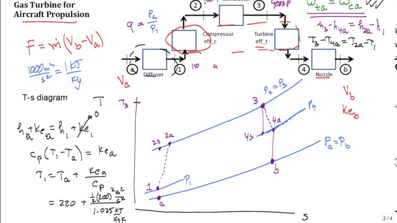
Jet engine, air-standard analysis
33.2K
Jet engines produce thrust through mass flow rate multiplied by exit velocity. Major components include diffuser (slows flow, increases pressure), compressor (raises pressure), combustor (adds heat), turbine (extracts work), and nozzle (converts pressure to velocity). The nozzle achieves high exit speeds by expanding high-pressure, high-enthalpy gas to lower exit pressure. On a temperature-entropy diagram, the diffuser shows pressure increase with minimal entropy change. The turbine extracts just enough work to drive the compressor, with the remaining pressure drop going through the nozzle for thrust generation.
Click to watch →
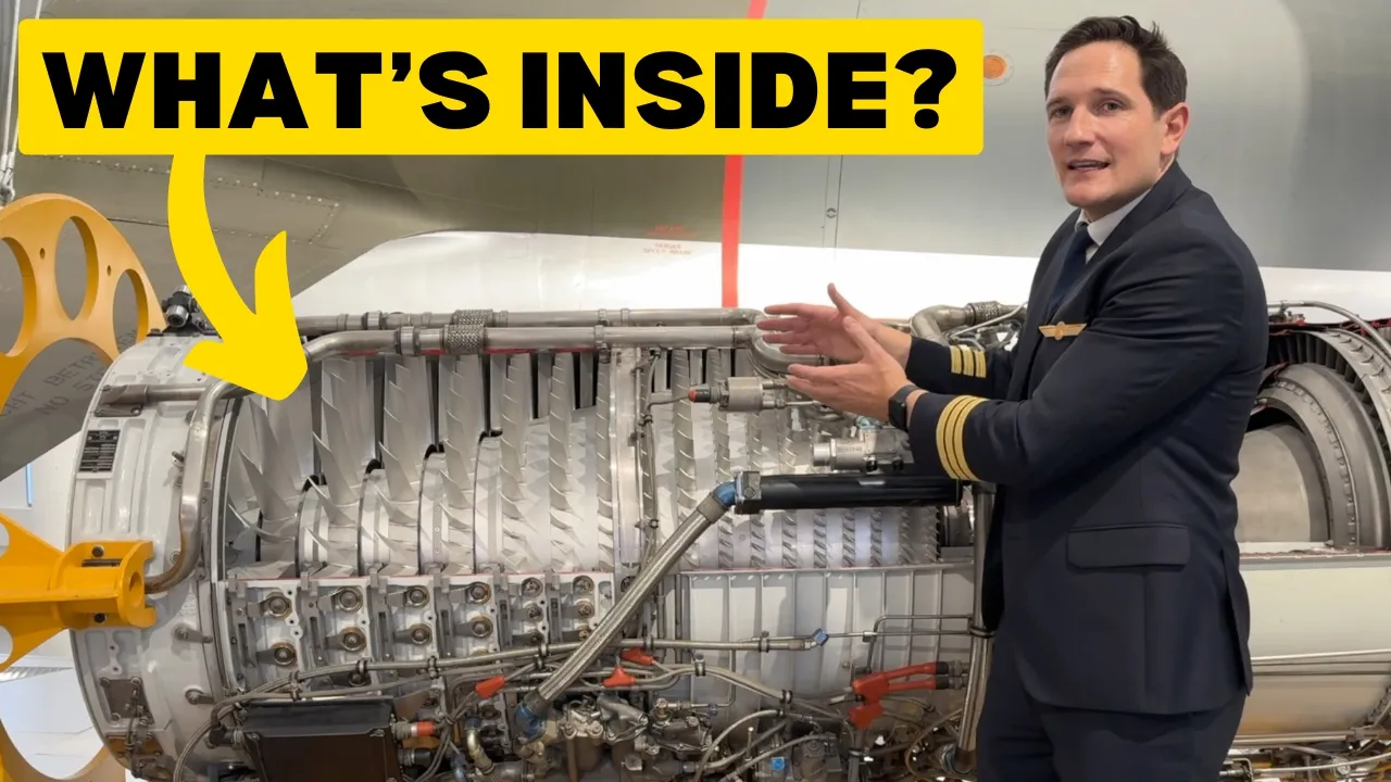
How a TURBOJET Engine works - Explained by CAPTAIN JOE
143.5K
A turbojet engine operates on the Brayton thermodynamic cycle, consisting of four main phases: air is sucked into the engine and compressed by an axial compressor (increasing pressure and temperature), then mixed with fuel and burned in the combustion chamber at constant pressure (reaching temperatures up to 2000°C), followed by expansion through a turbine that extracts energy to power the compressor, and finally expelled through a nozzle at high velocity to generate thrust; the key design parameters are the overall pressure ratio (compression efficiency) and turbine entry temperature (limited by blade material capabilities).
Click to watch →

India’s jet engine dilemma : British Rolls-Royce, France Safran or Japan's Monster XF9?
257
The hot section of a jet engine (high-pressure compressor exit, annular combustor, high-pressure turbine nozzles and blades, and low-pressure turbine inlet) operates at temperatures far exceeding the melting point of advanced nickel-based superalloys, which typically withstand only 1300-1350°C. Without mastery of this temperature zone, no compressor or fan optimization can deliver required thrust-to-weight ratio, specific fuel consumption, durability, or supercruise capability. Specific thrust scales with the square root of turbine inlet temperature—every 100°C increase yields 10-12% more thrust or 3-4% better fuel consumption. Current military engines target 1600-1800°C turbine inlet temperatures, far above superalloy melting points. This gap is bridged by four key technologies: single crystal superalloys eliminating grain boundaries that cause creep, thermal barrier coatings providing 100-200°C insulation, internal and film cooling systems protecting blades, and ceramic matrix composites enabling higher temperatures with reduced weight.
Click to watch →

한국 터보팬 엔진 기술 이미 F-16, 타이푼급 엔진 능가! ㅣ한국이 만든 터보팬 엔진이 세계 전투기 엔진 역사를 다시 쓰게 만든 이유ㅣ F-22 엔진과 기술격차 또 줄였
178.3K
Turbine inlet temperature is the absolute standard for measuring fighter jet engine performance. Higher temperatures directly correlate with greater thrust and overall engine efficiency. For example, Russia's AL-31F engine operates at approximately 1,400-1,500°C, while the latest Izdeliye 30 engine reaches around 1,600°C. The American F135 engine, used in the F-35 Lightning II, can withstand temperatures exceeding 1,980°C, making it one of the most powerful fighter engines in service.
Click to watch →

ME4293 Jet Engines 2 Fall2016
803
In jet engine analysis, the turbine must produce work equal to the compressor's consumption, requiring calculation of actual turbine exit temperature first using T4_actual = T3 - (T2_actual - T1), then determining isentropic properties through efficiency relationships, and finally calculating nozzle exit velocity and thrust using the momentum equation Thrust = ṁ(V_B - V_A).
Click to watch →
Deep Dive
The phenomenon of material creep (slow, progressive deformation under constant stress at high temperatures) and why it is a primary failure mode in turbine blades.

MATERIAL SCIENCE FOR ESE GS PART 1 (MOST IMPORTANT FOR PRELIMS)
1.7K
Fatigue is failure under repeated fluctuating loads even when stress is below ultimate strength. Cyclic loading causes progressive damage leading to sudden fracture. Creep is slow, gradual deformation under constant load at elevated temperatures, significant in turbine blades and jet engines. The creep curve shows three stages: primary (decreasing rate), secondary (steady rate), and tertiary (accelerating to failure). Materials resist creep by eliminating grain boundaries (weak points) through crystal pulling techniques. Both fatigue and creep are critical failure modes in high-temperature and cyclic loading applications.
Click to watch →

Tecnología de materiales, manufactura y enfriamiento en álabes de turbina (1/3)
297
Creep is slow, irreversible deformation under constant high-temperature load, a critical failure mode progressing through primary, secondary, and tertiary stages. The tertiary stage accelerates deformation toward fracture. Unlike fatigue (cyclic loading), creep occurs under constant conditions. The turbine disk, connecting blades to the fan shaft, is classified as a critical FAA-controlled part because failure can cause catastrophic aircraft damage. This classification mandates rigorous material standards for blade attachment systems.
Click to watch →
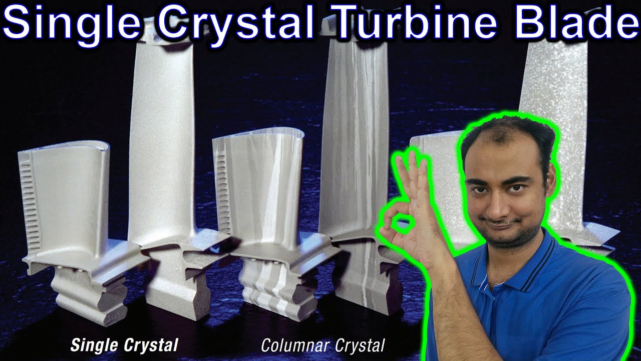
Single Crystal turbine Blade Explained {Science Thursday}
3.3K
Creep is a time-dependent deformation that occurs in materials under constant load at elevated temperatures. At room temperature, materials can easily handle applied loads, but when heated to as low as 600°C, even initially stable materials will gradually deform over time. For turbine blades operating continuously under high centrifugal forces, this means the blade may stretch after 3 hours, begin scraping against adjacent components after 4 hours, and develop cracks after 6 hours. This progressive failure mode is why creep resistance is a primary design consideration for high-temperature engine components.
Click to watch →

Turbine Blade Creep Life Prediction | Creep Failure in Turbine Blades
1K
Creep deformation in high-temperature materials occurs through three primary mechanisms: hardening, recovery/softening, and damage accumulation. When stress is applied, back stresses develop in crystal structures between slip planes, resisting further deformation. Temperature provides activation energy enabling dislocations to overcome these obstacles, causing recovery and softening. The continuous cycle of hardening and recovery leads to void formation at grain boundaries. Creep progresses through three distinct stages: primary stage with minimal cavity formation, secondary stage with steady-state cavity development, and tertiary stage with rapid crack propagation and accelerated failure. These mechanisms explain why gas turbine blades fail not only at roots but throughout their length, despite local stress values sometimes exceeding material strength.
Click to watch →

The Chinese got us! - How China caught up with jet engine technology
212.4K
The second failure mode is creep, which is the tendency of metal to be permanently deformed even when stress is not high enough to cause macroscopic permanent deformation. Creep happens at the micro level inside the material because the grain structure within the metal may move relatively to each other and remain locked in a different position. If creep grows too much, the turbine and spool may become unbalanced or the blade may start interfering with other components, potentially leading to structural failure.
Click to watch →
Deep Dive
An introduction to superalloys, specifically nickel-based superalloys, and why they maintain mechanical strength at elevated temperatures.

Non-Ferrous Metals & Alloys
5.3K
Nickel-based superalloys are designed for extreme high-temperature applications using two strengthening mechanisms: solid solution strengthening (adding alloying elements creates strain fields impeding dislocation movement) and precipitation hardening (excess alloying elements precipitate as fine particles creating additional strain fields). Typical compositions include 10-20% Cr, 8% Al, 5-10% Co, plus B, Zr, and C. Chromium and aluminum improve oxidation resistance through protective oxide layers. Molybdenum and tungsten form hard carbide precipitates. These mechanisms allow retention of strength at elevated temperatures where conventional strengthening methods fail, making these alloys essential for turbine blades, rocket engines, and pressurized water reactors.
Click to watch →

The essence of nickel-based superalloys
380
Nickel-based superalloys achieve exceptional high-temperature strength through a dual-phase microstructure consisting of a gamma matrix (face-centered cubic) reinforced by gamma-prime precipitates (ordered primitive cubic), where the coherent interface between these phases creates negative misfit stresses that lock dislocations and resist creep deformation; modern engineering further enhances performance through single-crystal casting to eliminate grain boundary weaknesses, bond coat layers that provide oxidation resistance, and ceramic thermal barrier coatings that reduce surface temperatures by up to 300°C, though these protective layers introduce thermomechanical fatigue challenges due to differing thermal expansion coefficients.
Click to watch →

Specialty Alloys Webinar: What you need to know about welding Nickel Alloy filler metals.
1.2K
Nickel-based superalloys emerged in the last 70 years for gas turbine applications, containing up to 10 alloying elements including chromium, molybdenum, boron, and hafnium. Their strength derives from a face-centered cubic austenitic gamma matrix reinforced by gamma prime intermetallic precipitates (Ni3(Al,Ti)) that lock grain boundaries. Additional strengthening comes from carbides and borides distributed throughout the matrix. These alloys maintain mechanical properties at 85% of their melting points and resist pitting, crevice, intergranular, and stress corrosion cracking. Key applications span petrochemical, oil and gas, nuclear, and LNG industries.
Click to watch →

Superalloys Explained: Jet Engine Materials & Strengthening Mechanisms
2.6K
Nickel-based super alloys achieve exceptional high-temperature performance through three complementary strengthening mechanisms: solid solution strengthening, precipitation hardening, and carbide/boride strengthening. Solid solution strengthening occurs when alloying elements (Cr, Mo, Al, Nb, Ti) occupy substitutional or interstitial positions in the nickel lattice, creating lattice distortions that hinder dislocation motion. Precipitation hardening involves aluminum and titanium forming intermetallic compounds (gamma prime phase, Ni3(Al,Ti)) that precipitate within the primary nickel matrix, acting as obstacles to dislocation movement. Carbide/boride strengthening results from carbon and boron forming carbides/borides (M23C6, MC, M6C) along grain boundaries, which segregate during service life and provide additional strengthening through dispersion mechanisms. Common compositions include Inconel 750 (75% Ni, 19.5% Cr) and Inconel 800 (80% Ni, 19.5% Cr). Applications span aerospace gas turbine engines, space vehicle rocket engines, nuclear reactors, power generation turbines, submarines, petrochemical equipment, and hot working tools—any environment involving sustained high temperatures where conventional materials would fail.
Click to watch →

Metals and Alloys, lecture 12, Alloys for Elevated Temperatures
13.8K
Nickel-based superalloys contain gamma (disordered FCC Ni-Al) and gamma prime (ordered Ni3(Al,Ti) with primitive cubic structure). By matching lattice parameters through Al/Ti adjustment, coherency is achieved between phases. Order hardening occurs when dislocations encounter gamma prime: matrix dislocations must form paired superdislocations with <111> Burgers vectors to penetrate ordered precipitates. These paired dislocations repel each other but remain bound by anti-phase domain boundaries of disrupted order. Typical alloys contain ~70% gamma prime precipitates. Pure gamma prime alloys show increasing strength with temperature due to cross-slip difficulties, but commercial viability fails due to impurity sensitivity affecting ductility.
Click to watch →
Prerequisite Knowledge
- Concept 01Basic crystallography and materials science, including the concepts of crystal lattices, grains, and grain boundaries in polycrystalline metals.
- Concept 02Fundamentals of jet engine thermodynamics, particularly how turbine entry temperature relates to overall engine efficiency and thrust.
- Concept 03The phenomenon of material creep (slow, progressive deformation under constant stress at high temperatures) and why it is a primary failure mode in turbine blades.
- Concept 04An introduction to superalloys, specifically nickel-based superalloys, and why they maintain mechanical strength at elevated temperatures.
Subsequent Learning
- Step 01The precise manufacturing process of single crystal blades, including directional solidification and the use of spiral/pigtail crystal selectors.
- Step 02Advanced cooling technologies implemented inside and on the surface of turbine blades, such as film cooling and internal serpentine passages.
- Step 03Thermal Barrier Coatings (TBCs) and environmental coatings applied to superalloy blades to withstand temperatures exceeding the alloy's melting point.
- Step 04Next-generation aerospace materials, such as Ceramic Matrix Composites (CMCs), which aim to replace single crystal superalloys for even higher temperature capabilities.
Turbine Blade Creep
Single Crystal Impact
Turbine Blade Creep
0:00Playing Section
- 1
Explains creep failure from high temperature centrifugal forces.
- 2
Details microstructural evolution from polycrystalline to columnar grains.
Ceramic Matrix Composites (CMCs) and the Economic Limits of Single-Crystal Alloys
While single-crystal (SX) superalloy blades offer superior creep resistance by eliminating grain boundaries, they represent a pinnacle of manufacturing cost, complexity, and resource intensity. The production of SX blades involves slow, highly controlled vacuum casting with high reject rates, making them economically impractical for many applications where directionally solidified (DS) or conventionally cast alloys are more cost-effective. Furthermore, nickel-based SX alloys are reaching their thermodynamic limits. Ceramic Matrix Composites (CMCs) have emerged as a major disruptive alternative. CMCs can operate at temperatures hundreds of degrees hotter than nickel superalloys while weighing a fraction of the mass. This allows engines to run hotter and more efficiently without the complex, performance-reducing cooling systems required by SX metallic blades, challenging the future dominance of single-crystal metallurgy in turbine design.
Deep Dive
The precise manufacturing process of single crystal blades, including directional solidification and the use of spiral/pigtail crystal selectors.

DRDO finally makes single crystal turbine blades for aeroengines.
262
Single crystal blade technology represents the pinnacle of modern metallurgy and precision manufacturing. Unlike multi-crystal materials where grain boundaries (interfaces between different crystal grains) are primary failure points under extreme conditions, single crystal blades are cast as one continuous crystal structure, eliminating all grain boundaries. The manufacturing process uses investment casting with directional solidification: the mold is slowly withdrawn from a furnace in a cooling chamber, and a grain sector filter allows only one crystal to grow into the cavity. This technology was developed in the 1980s and enables blades to operate at temperatures 200-300°C above the melting point of the base alloy without melting or failing. The technology is highly valuable and not shared by other countries because it represents a continuous source of income and technological advantage.
Click to watch →

The "Tofu-Dreg" War: Why American Science Always Wins the Metallurgy Battle.
190
Single crystal blade production requires extreme precision: vacuum chambers to prevent oxygen contamination, ceramic molds at 1,500°C, and withdrawal rates measured in millimeters per hour. The Bridgman process creates a single crystal by slowly lowering the mold from hot to cool zones, with a spiral selector ensuring only one crystal survives. After casting, heat treatments coax gamma prime precipitates into precise patterns. Machinists trim blades to thousandths of an inch tolerances. Nondestructive evaluation using X-ray CT and ultrasonic testing hunts for invisible flaws. The yield is ruthless—over 95% must pass, but failures are not forgiven. A batch of 40 blades costs over $600,000.
Click to watch →

Por que os motores a jato não derretem?
455.1K
Directional solidification creates columnar crystals aligned along the blade's axis, making it significantly more resistant than cast alloys with randomly oriented crystals. Scientists found an even better method by inserting a helical curve (pigtail) in the mold above the cooling plate. This curve eliminates all other grains except one, allowing a single crystal to grow throughout the blade. After solidification, the blade is reheated almost to its melting point to allow atoms to distribute uniformly and form the final gamma and gamma prime microstructure. The orientation of the crystal is fundamentally important—different orientations have different stress responses. Today, over 95% of turbine blades can be cast as single crystals, reducing from 50,000 grains to just one.
Click to watch →

L'Astuce Physique Pourquoi Les Moteurs D'Avion Ne Fondent Pas À 2000 Degrés
196
Single crystal turbine blades are manufactured by pouring molten superalloy into a preheated ceramic mold, then slowly withdrawing it (a few centimeters per hour). A spiral selector at the mold base blocks all crystal nuclei except one, ensuring a single crystal orientation propagates throughout. The internal cooling core is dissolved using alkaline caustics, and cooling holes are drilled by electrical discharge machining. First introduced in commercial aviation in 1980 on the Boeing 747, single crystal blades are now produced at 8 million units annually by major manufacturers. While the principles are published, the execution requires decades of accumulated industrial expertise that cannot be replicated by patents alone.
Click to watch →

Sekret Fizyki Dlaczego Silniki Odrzutowe Nie Topią Się Przy 2000 Stopniach Świata
1.8K
The process leading to this is extremely precise. Molten superalloy is poured into a ceramic mold heated almost to the metal's melting point. Then the mold is withdrawn from the furnace at a speed measured in centimeters per hour - almost absurdly slow for something that will later spin in a jet engine. As it withdraws, the mold allows metal to solidify from bottom to top. At its base, a spiral selector blocks all crystal nuclei except one. Only one grain orientation passes through the entire mold. The ceramic core inside the blade, which created the hollow cooling channels, is later dissolved with alkaline compounds. Cooling holes are made by electro-erosion. The thermal barrier coating is applied by electron beam deposition. The finished blade is tested by X-ray diffraction to confirm it is truly a monocrystal from end to end.
Click to watch →
Deep Dive
Advanced cooling technologies implemented inside and on the surface of turbine blades, such as film cooling and internal serpentine passages.

Mod-01 Lec-29 Components of the Gas Turbine Engine
11.4K
Modern turbine blade cooling employs multiple sophisticated techniques: internal hollow passages route coolant air through circuitous paths for maximum cooling coverage; film cooling ejects coolant through small holes to create protective air films insulating blades from 1500-1600°C gases; impingement cooling directs jets onto blade surfaces for maximum heat transfer at stagnation points; protrusions promote turbulent flow enhancing heat transfer. These technologies enable blades to operate at approximately 2200 K, compared to current operational temperatures of 1800 K, representing a 400-500 K margin above blade material limits.
Click to watch →

Mod-01 Lec-28 Turbine Blade Cooling Technologies
68.4K
Turbine blade cooling is essential for modern gas turbines because material science cannot withstand the extreme temperatures required for efficient operation (around 1000-2000 K). The cooling technology has evolved over approximately 50 years through several generations: internal convection cooling (passages carrying cold air through the blade), film cooling (cold air exiting through holes to create a protective film on the surface), and impingement cooling (cold air jets striking the blade surface). These technologies work together to manage the significant temperature gradients along the blade (200-300°C variation from leading to trailing edge) and prevent thermal fatigue and creep failure. Modern advanced cooling systems can achieve turbine entry temperatures near 2000 K while using less than 1% of the main gas flow as coolant, representing a critical advancement in turbomachinery efficiency.
Click to watch →

Mod-01 Lec-21 Multi-staging: Axial Turbine; Turbine Cooling Technology
4K
Modern turbine blade cooling employs multiple integrated technologies: internal convection cooling using ribbed passages, impingement cooling directing jets at inner surfaces (particularly effective at leading edges), and film cooling creating protective air layers through precisely drilled holes. Transpiration cooling using porous materials represents future technology. Coolant flow requirements increase with turbine inlet temperature, typically requiring 500°C temperature difference between blade and mainstream gas. Thermal barrier coatings supplement active cooling. Each blade requires unique cooling design, making manufacturing extremely costly. These technologies enable current 1800-1900K operation, with research targeting even higher temperatures through advanced material and cooling technology development.
Click to watch →

Apreciando la Belleza de los Motores Jet Comparándolos con los Motores de Pistón
202.8K
Jet engine turbine blades use advanced cooling techniques including hollow shafts with air holes. Air is carried through the shaft to the interior of the blades, which are perforated so air escapes through perforations to form a protective air film on the blade surfaces. These cooling methods allow turbines to withstand the extreme temperatures generated during combustion.
Click to watch →

Prototyping cylinder heads - Redrup Radial EP.6 || RotarySMP
21.6K
High-pressure turbine blades survive extreme temperatures through film cooling technology. Cool air is forced through small holes in the blade surface, creating a protective layer of cooler air between the hot combustion gases and the metal blade surface. This film prevents direct impingement of hot gases on the metal, significantly extending blade life. When film cooling holes become clogged (often by debris from bird strikes), the protective cooling effect is lost, causing rapid blade deterioration and cracking.
Click to watch →
Deep Dive
Thermal Barrier Coatings (TBCs) and environmental coatings applied to superalloy blades to withstand temperatures exceeding the alloy's melting point.

Materialism Podcast Ep 48: Thermal Barrier Coatings
3.8K
Thermal barrier coatings (TBCs) are ceramic layers, typically made of yttria-stabilized zirconia (YSZ), applied to nickel superalloy turbine blades to protect them from extreme operating temperatures that would otherwise cause melting; these coatings work by creating a significant temperature gradient across their thin structure (as thin as a fingernail) through low thermal conductivity, while also accommodating thermal expansion mismatches between the ceramic and metal substrate through specialized microstructures like columnar structures in electron beam physical vapor deposition coatings.
Click to watch →
Sekret Fizyki Dlaczego Silniki Odrzutowe Nie Topią Się Przy 2000 Stopniach Świata
1.8K
Turbine blades in modern jet engines operate at temperatures exceeding their melting point (1600-1800°C) while the nickel-based superalloys melt at 1200-1400°C. Engineers maximize the temperature margin between operating conditions and material failure. The first protection layer is a ceramic thermal barrier coating (yttria-stabilized zirconia, 100 micrometers to 2mm thick) applied via physical vapor deposition. This coating reduces blade surface temperature by up to 300°C by acting as a thermal wall rather than a highway. The coating is bonded at the molecular level to the underlying metal, creating a barrier that slows but does not stop heat transfer.
Click to watch →

One Week One Theme DAY 2
129
CSIR-NAL developed high-temperature coatings for gas turbine engines operating from 350-400°C at inlet to 1,200°C at outlet. Three coating types were developed: Thermal Barrier Coatings (TBCs) for turbine blades achieving 120°C temperature drop with thermal conductivity 0.5-1.0 W/m·K (vs 2 W/m·K commercial), Environmental Barrier Coatings (EBCs) for composite components providing moisture resistance, and erosion-resistant coatings for compressor blades. TBCs achieved >100 thermal cycles and 10x lower erosion rates than commercial coatings. Erosion-resistant nano coatings using DC pulse laser plasma spray achieved 74x higher erosion resistance than bare substrate. All coatings use indigenous powder synthesis through spray drying and combustion synthesis methods.
Click to watch →
Lecture 15_Thermal Barrier Coatings for Gas Turbine Blades
447
Thermal barrier coatings (TBCs) are multi-layer ceramic coatings applied to gas turbine blades to protect them from extreme heat, consisting of a 7% yttria-stabilized zirconia top coat, a thermally grown oxide (TGO) layer, and a bond coat on a nickel-based super alloy substrate; these coatings function by providing thermal insulation, strain compliance to minimize thermal expansion mismatch, radiant heat reflection, and service life extension, enabling gas turbines to operate at higher temperatures (up to 1400°C) which improves thermal efficiency while preventing creep and fatigue failures.
Click to watch →
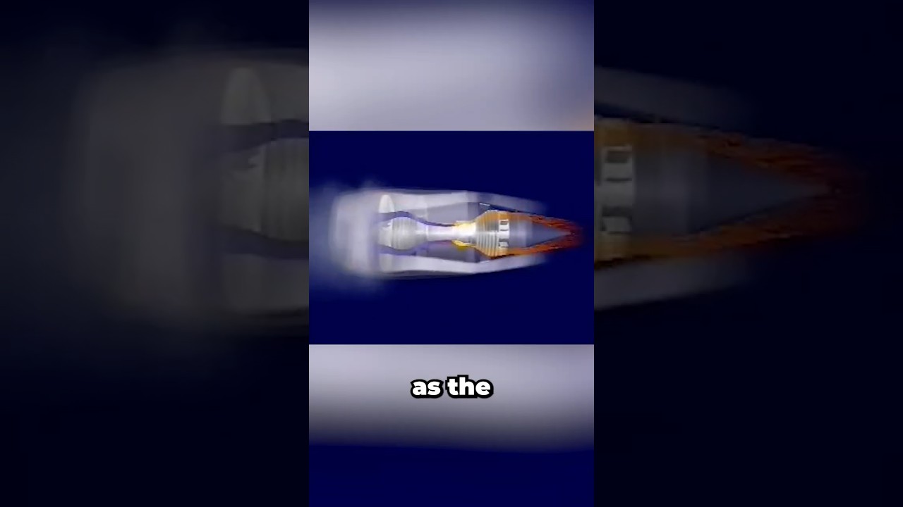
What stops jet engines from melting instantly?
41.4K
Jet engines use multi-layer thermal barrier coatings on turbine blades to prevent melting despite operating temperatures exceeding the metal's melting point; these coatings consist of a bond coat that protects against corrosion and grows a thermally grown oxide layer, and an outer ceramic layer with columnar structure that provides strain relief and reduces heat transfer by approximately 250°C, working together with internal cooling systems to protect the blades.
Click to watch →
Deep Dive
Next-generation aerospace materials, such as Ceramic Matrix Composites (CMCs), which aim to replace single crystal superalloys for even higher temperature capabilities.

2012 ALS User Meeting Robert Ritchie
516
Ceramic matrix composites (CMCs) represent a revolutionary material for aerospace engines, enabling operation 200-400°C higher than nickel superalloys (currently limited to 1150°C). CMCs provide 20-30% weight reduction and eliminate cooling requirements. They are three-dimensional architectures of carbon, graphite, or silicon carbide fibers woven into matrices with chopped fibers and gradients. The key challenge is ensuring survival of bird strikes without catastrophic failure. Tomography characterizes fiber shapes, sizes, positions, and stresses in three dimensions. This data feeds into geometry generators creating synthetic materials with correct statistical properties. The complexity of these materials requires understanding damage mechanisms, particularly how cracks form in the matrix and propagate along fibers.
Click to watch →
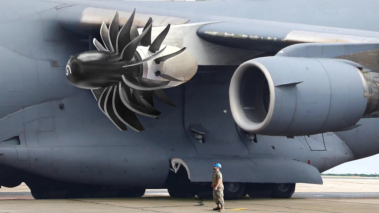
US and Europe Testing World’s Most Advanced Aircraft Engines Ever Made
2M
Ceramic Matrix Composites (CMCs) are made from ceramic fibers embedded in a ceramic matrix, offering advantages over traditional metallic materials including lightweight properties and corrosion resistance. CMCs represent the next generation beyond metallic alloys used in aircraft engines for the past 20-30 years. GE's material system incorporates thousands of fibers smaller than human hair diameter into ceramic material, providing great durability. These materials enable aircraft engines to operate at much higher temperatures.
Click to watch →

Hypersonix and Advanced Ceramic Matrix Composites!
8.1K
This extensive section explores how advanced materials enable next-generation aerospace systems. Ceramic Matrix Composites (CMCs) combine ceramic matrices with reinforcing fibers to overcome ceramic brittleness. Oxide ceramics (alumina, zirconia) offer high-temperature stability but poor mechanical properties; non-oxide ceramics (nitrides, carbides, borides) maintain strength at elevated temperatures. Silicon carbide is particularly valuable, used in rocket engine nozzles including SpaceX's Raptor. The manufacturing process involves spinning polycarbosilane into fibers, applying proprietary coatings, creating fiber tape, stacking plies with alternating orientations, autoclave processing, burnout, and silicon infiltration. Over 50 steps produce parts withstanding 2,400°C. Three CMC techniques exist: CVI (gas infiltration), LPI (liquid precursor), and PIP (polymer pyrolysis). NASA's GRX 810 super alloy combines nickel, cobalt, chromium with nanoscale yttrium oxide for twice the strength and 1,000x durability at 1,100°C. Together, these materials could enable single-stage-to-orbit space planes taking off from runways and reaching destinations like the Moon.
Click to watch →

Selecting Ceramic Matrix Composites for Your Next High Temperature, Critical Application
564
Ceramic Matrix Composites (CMCs) are reinforced ceramic materials that improve fracture toughness by using ceramic fibers to bridge, deflect, and impede crack propagation, offering significant advantages over monolithic ceramics and super alloys including a temperature range of 1000°C to 2700°C, one-third the weight of nickel super alloys, and inherent oxidation resistance; these materials are manufactured through prepreg processes involving autoclave cure followed by sintering, with fiber options like Nextel 610 (alumina), 720 (aluminum mullite), and 312 (mullite) each offering different trade-offs between structural performance, creep resistance, and dielectric properties for applications in aerospace engines, refineries, and radomes.
Click to watch →

Ceramic matrix composite | Wikipedia audio article
386
CMCs overcome conventional ceramic limitations of brittle failure, low fracture toughness, and limited thermal shock resistance, enabling applications requiring reliability at extreme temperatures beyond metal capabilities. Space vehicle heat shields during re-entry face temperatures above 1500°C for minutes, surviving only with ceramics, and only CMCs handle thermal shocks adequately. High temperatures preclude oxide fiber CMCs due to excessive creep; amorphous SiC fibers lose strength above 1250°C, so carbon fiber-reinforced SiC (C/SiC) is used. ESA's Hermes program (1980s) produced initial results, followed by NASA X-38 development qualifying C/SiC bolts, nuts, and bearing systems tested at DLR Stuttgart under 1600°C, tonnes load, and 4 cycles/second movements for 5 simulated re-entries. ESA's Intermediate Experimental Vehicle (IXV) uses C/SiC thermal protection. In gas turbines, CMCs enable higher inlet temperatures improving efficiency. US tested SiC/SiC combustors for 15,000 hours with oxidation protection coatings. GE-Rolls-Royce studied CMC stator vanes; CFM International uses CMC turbine shrouds; GE employs CMCs in combustor liners, nozzles, and shrouds for GE 9x engines. After $1.5 billion investment over 20 years, GE targets 44,000 pounds/year CMC prepreg production by 2020. Oxide CMCs serve burner and hot gas ducts in oxygen-containing environments above 1000°C, with lifetimes several times longer than metals. C/SiC brake discs offer 300,000 km lifetime, no fading, 40% lower mass than metals, and better corrosion resistance. Slide bearings using SiC/SiC show almost triple specific load capability compared to conventional systems, with successful testing in liquid oxygen environments for rocket turbo pumps.
Click to watch →
Turbine Blade Creep
Single Crystal Impact
Turbine Blade Creep
0:00- 1
Explains creep failure from high temperature centrifugal forces.
- 2
Details microstructural evolution from polycrystalline to columnar grains.
Ceramic Matrix Composites (CMCs) and the Economic Limits of Single-Crystal Alloys
While single-crystal (SX) superalloy blades offer superior creep resistance by eliminating grain boundaries, they represent a pinnacle of manufacturing cost, complexity, and resource intensity. The production of SX blades involves slow, highly controlled vacuum casting with high reject rates, making them economically impractical for many applications where directionally solidified (DS) or conventionally cast alloys are more cost-effective. Furthermore, nickel-based SX alloys are reaching their thermodynamic limits. Ceramic Matrix Composites (CMCs) have emerged as a major disruptive alternative. CMCs can operate at temperatures hundreds of degrees hotter than nickel superalloys while weighing a fraction of the mass. This allows engines to run hotter and more efficiently without the complex, performance-reducing cooling systems required by SX metallic blades, challenging the future dominance of single-crystal metallurgy in turbine design.
Basic crystallography and materials science, including the concepts of crystal lattices, grains, and grain boundaries in polycrystalline metals.
Fundamentals of jet engine thermodynamics, particularly how turbine entry temperature relates to overall engine efficiency and thrust.
The phenomenon of material creep (slow, progressive deformation under constant stress at high temperatures) and why it is a primary failure mode in turbine blades.
An introduction to superalloys, specifically nickel-based superalloys, and why they maintain mechanical strength at elevated temperatures.
The precise manufacturing process of single crystal blades, including directional solidification and the use of spiral/pigtail crystal selectors.
Advanced cooling technologies implemented inside and on the surface of turbine blades, such as film cooling and internal serpentine passages.
Thermal Barrier Coatings (TBCs) and environmental coatings applied to superalloy blades to withstand temperatures exceeding the alloy's melting point.
Next-generation aerospace materials, such as Ceramic Matrix Composites (CMCs), which aim to replace single crystal superalloys for even higher temperature capabilities.
966.7K views18.5Klikes2:50@QHead-007Original Release: 2026-01-02
So you have a big shaft on which there are this small small turbine blades which are mounted and they are rotating at thousands of RPM and at such high RPM and such high temperatures above 1,000°C they would be subjected to loading. So there is centrifugal force acting on each of the blades and there are hot gases passing over it. The scientists realized that the failure of the blade that happens because of high temperature deformation is what is called as creep.
Initially engine manufacturers might have started with some material but then eventually they came to nickel alloys and then when they started making nickel alloys they realized that if it has a poly crystalline microructure polyrystalline means let's say if you're looking at a micro structure you have lots of grain maybe hundreds of grains.
A grain is comprises of all of the atoms which are nicely arranged in one given pattern. So they have one particular crystalallographic orientation. So they realize the creep failure happens sooner. If you have a poly crystalline microructure they realize that most of the loading is happening radially. If let's say we do not have any grains which are perpendicular to it that would also improve the life. Then they evolved the process to making columnar microructure where you will have grains but most of those grains would be single from bottom till the top. To make it a columnar grain you cannot do it using a traditional casting process. You use something called as a bridgeman type of solidification process. If you can control the solidification process such that the liquid solidifies in one direction then you can get the columnar growth. So that was one thing.
Scientists were like okay how can we make it one single grain. How do we do that? Scientists figured out a way so that you know you can reduce the number of grains by starting your casting little bit away from your blade geometry. This particular alloy was invented and then the blades they started manufacturing as single crystal.
>> Single crystal means grain is just one single grain.
>> Wow. Okay. Okay. So it was I think decades of work several industries you know working on their own.
>> So what was the impact after that material? You got better properties you have better creep life. So you can increase that temperature at which the gases are exiting the combustion chamber. So you can now take those temperature higher. So increase the efficiency of the planes. So now you increase efficiency your fuel consumption reduces the flight duration >> cost >> cost the efficiency increase so your power increase >> planes can go faster you can travel longer distances with the same amount of fuel
Up Next
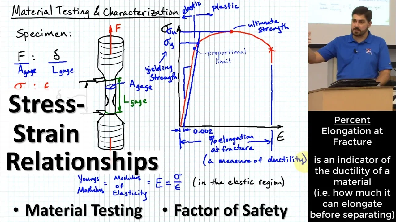
98:38
Stress-Strain Relations: Tensile Testing & Material Strength
@TheBomPE
81.2K views•2019-09-16

30:32
Ultrasonic Transducers: Resonant Frequency Measurement and Horn Design
@imajeenyus42
229.9K views•2017-02-22

54:16
Polymer Environmental Degradation: Mechanisms & Stabilization
@iit
1.8K views•2012-07-10

33:39
How a Student's Question Saved a NYC Skyscraper from Collapse
@veritasium
22.8M views•2025-04-26
Related Study Plans & Knowledge Roadmaps
Structured learning paths in Engineering
engineering
Building Acoustic Levitators: Physics & Arduino
01The Physics of Sound and Standing Waves
02Piezoelectric Transducers and H-Bridge Drivers
03Arduino Programming: Generating 40 kHz Signals
+ 2 more learning modules
14h5 modules
Explore Roadmap
engineering
Building Peltier Cloud Chambers: Particle Tracks
01Cosmic Rays & Cloud Chamber Physics
02Thermoelectric Cooling (TEC) Fundamentals
03Custom Liquid-Cooling Loop Design
+ 2 more learning modules
18h5 modules
Explore Roadmap
engineering
Yagi-Uda Antennas: Modeling, Build & VNA Test
01Introduction to RF and Antenna Fundamentals
02Yagi-Uda Antenna Design Principles
03Antenna Modeling and Simulation in 4NEC2
+ 2 more learning modules
18h5 modules
Explore Roadmap
engineering
ECG Monitor Design: Op-Amps, Filters & Noise
01Electronics & Breadboard Basics
02Op-Amps and Instrumentation Amplifiers
03Bioelectricity and ECG Fundamentals
+ 2 more learning modules
18h5 modules
Explore Roadmap