








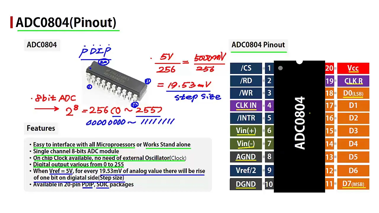
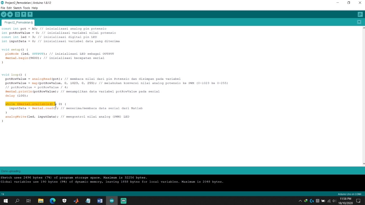
![Belajar STM32 & Arduino IDE [04]: Dasar Pemrograman ADC (Analog to Digital Converter)](https://i.ytimg.com/vi_webp/T4f8q91MspY/maxresdefault.webp)



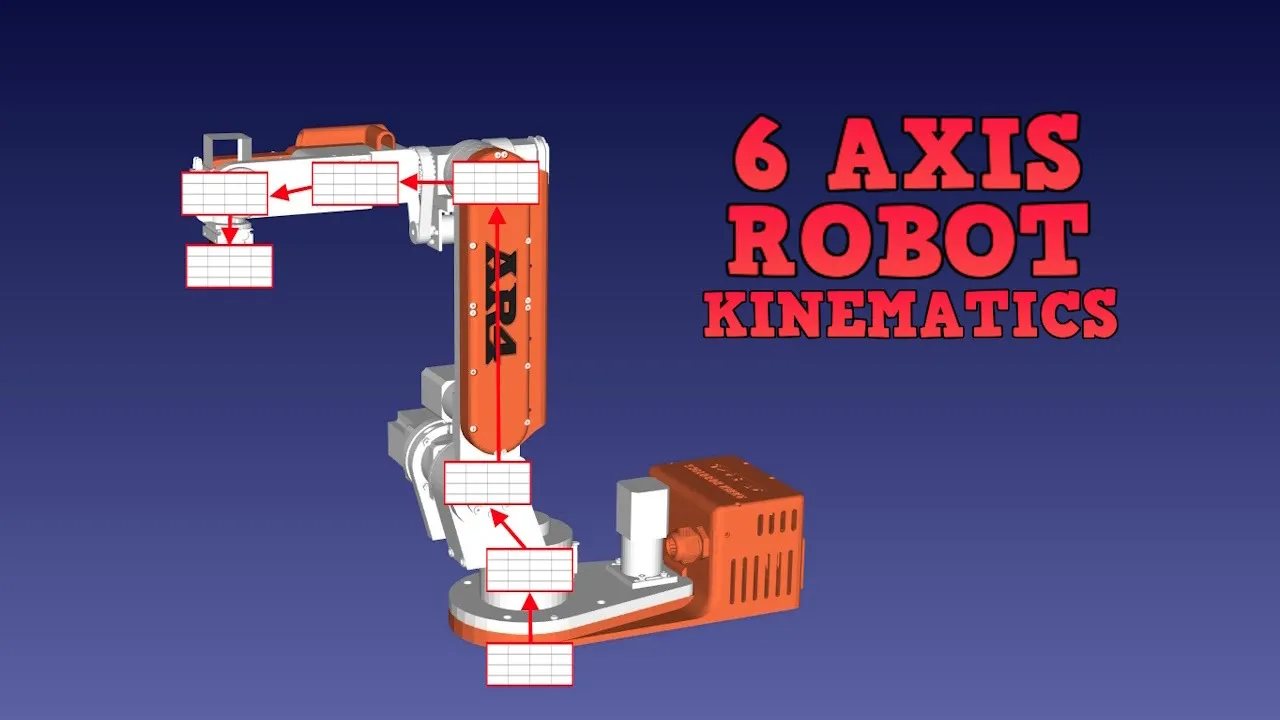



![[경희대 김동한] 2021-1 자동제어 (16)](https://i.ytimg.com/vi/smk2WGDENmA/maxresdefault.jpg)









This video demonstrates how to build an affordable 5 Degrees of Freedom (5DOF) robotic arm using 3D printing and hobby servo motors, with each joint containing a servo motor and potentiometer mounted on the same axis within a 3D printed enclosure; the electronics use a Raspberry Pi Pico W microcontroller with a CD4051 multiplexer to read six potentiometers on three ADC pins, implementing ramp mode in the code to smoothly move joints by incrementing angles gradually rather than jumping directly, which reduces inertia and prevents motor stalling.
Build a Low-Cost 5DOF 3D-Printed Robot Arm with Position Feedback
Added:Basic principles of robotics anatomy, specifically Degrees of Freedom (DOF) and rotational coordinate systems.
Fundamentals of microcontrollers (e.g., Arduino) and Pulse-Width Modulation (PWM) for controlling RC servo motors.
Electronic circuit basics, including voltage dividers, Analog-to-Digital Conversion (ADC), and how potentiometers function as analog sensors.
Introduction to 3D printing design considerations, such as structural tolerances, mechanical assembly, and material properties like PLA or PETG.
Forward and Inverse Kinematics (FK/IK) mathematical models to translate desired 3D coordinates into specific joint angles.
Closed-loop control systems, specifically implementing Proportional-Integral-Derivative (PID) controllers using the potentiometer feedback.
Trajectory planning and motion profiling to generate smooth paths and minimize mechanical wear caused by rapid joint movements.
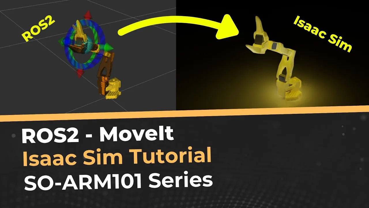
Integration with the Robot Operating System (ROS) and MoveIt for advanced 3D simulation, path planning, and obstacle avoidance.
202.7K views4.8Klikes31:04Original Release: 2023-11-10
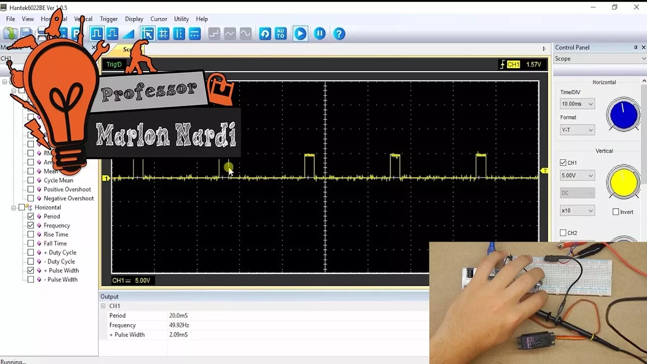
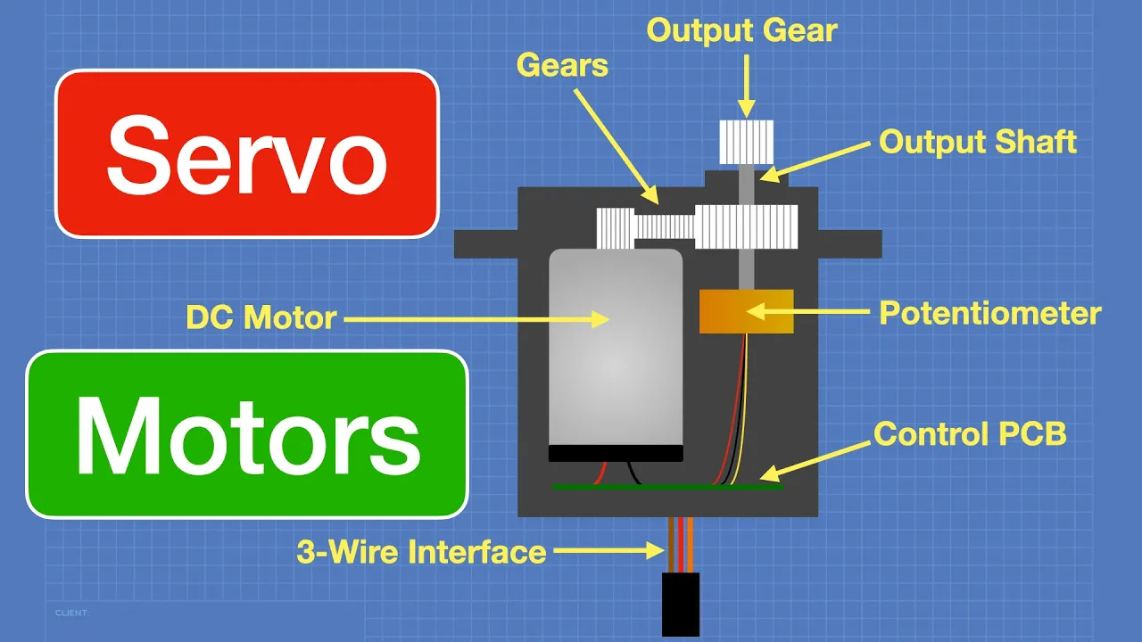
hi my name is Milos and welcome to element 14 presents today I will be talking about robot arms this here is a robot arm kit made by Arduino it is a robot arm that has 5 degrees of freedom it uses pretty powerful Servo Motors and it's pretty easy to assemble one problem about it it costs around €240 and while the kit itself is really made good and you even get a shield for ardino so you can easily connect the arm a power supply and things like that I thought with the wide availability of 3D printing now either by people having 3D printers maker spaces libraries and such things I thought how cheap can we actually go and make a pretty decent arm comparable to this let's get [Music] started let's take a look at the robot arm configuration first the Arduino arm we have the base joint the free three normal joints and another last joint that's oriented differently and the gripper on top for our arm I want to keep the same configuration use smaller servos to save on the cost and also get position feedback using a potentiometer that means we need to place a potentiometer on the other side of the servo and keep them on the same axis and we're going to put them in a 3D printed Cas enclosure and that will be our finished module okay now that you've seen the how the configuration of this arm goes let's take a look at the main components that actually make the arm move here in the middle of the black thing here are the servo Motors that actually control the robot arm joints these are hobby Sero Motors and here on the outside I've added potentiometers so you can actually track the position of each joint as it moves seral Motors at least the hobby ones most of them work with a potentiometer inside let's take a closer look at what makes actually a Ser motor how do we control it and we'll go from there so this is a drawing of a standard hobo motor that you can see around it has three pins power ground and Signal the ones we will be using have a plastic body two mounting hols and a motor shaft let's take a look at the inner workings of a Servo so inside it's a normal DC motor with a big gear reduction and on the output shaft of the gear there is a potentiometer which measures the angle and the PCB with a controller where we send it the signal and it tries keeping uh that value now there are other fancy servos that have rs485 communication or something else but these servos that we will be using uh they are controlled using what's called pvm or pulsewidth modulation so for these servos uh we tend to go around 2 to 300 Herz for example and for Z de we want a pulse width of 500 microc and for the other the 180° we want 2500 microc and that's how we control a Servo motor okay so let's take a look at how we will Design the module that holds the servo and the potentiometer first off I began by actually measuring the actual Servo and making a model out of it the next thing we need to do is actually place the potentiometer which you can see here so as mentioned for we want the both the shaft of the motor and the potentiometer to be on the same axis so that we can use that axis as the joint of the robot the thing now is that we need to do is design a 3D printed case that can both Mount the servo and the potentiometer the servo motor mounts using these two holes here and here while the potentiometer mounts just with a nut here so this is the box I designed that houses in both of them I tried making it as small as possible but I still wanted it to be aesthetically pleasing so it's just not just a skeleton box but an actual box and on top of that I added the lid okay now that you've seen the cad of the module let's assemble it first things first we need to insert the four M3 nuts here and cut the Frets here these threads aren't necessary but I like cutting them to get a more reliable connection uh first thing you want to do is insert your potentiometer I already soldered the wires okay now that that's done the next thing is to insert the servo motor the holes on the servo motor are 2.5 mm which is perfect for M3 screws so I cut the threets again to insert the Sero you need to fold this cable like this here a little bit less like this the next thing we need to do is attach the servo using the two screws don't tighten it too much so you don't uh strip the threads and it's a pretty snug fit so the server won't go anywhere and the last thing when it comes to the mechanical assembly is to add the cover okay so that's the finished module next thing we need to do is crimp the connectors I'll speed this part up okay the last thing to do is to actually put the pins into the connectors this is the board the final board that we will be using for controlling everything this side here uses these for the potentiometers and this side here is for the servo motor so the outside pin as it goes like this is for the ground pin which is the black pin here uh then in the middle is the 3.3 volt with which is the gray wire and in the end we have the signal wire which is the middle contact and in my case case that's the white wire and it clicked into place that connector is done now let's go to the servo connector uh the outside pin is again the uh ground so that's the Brown connect brown wire here that clicked into place the middle is the power for the servo there you go and the last one is the signal wire and it clicked all into place so this is a completely finished module now let's take a look at another thing and that's how do we actually attach These Arms to the module to do that we actually need to use a microcontroller or a function generator so uh there's a program on the Arduino Uno running which just turns the motor to 0° then to 180 and then back to 90 180 and and then 90 so why is that important it's important so we actually centered the Sero motor so we know that the center point is 90° so this is the Servo arm it has the servo plate that came with the servo motor I just glued it into place uh everything is uh exactly 24 mm wide they're the same so the easiest way to do this is Place both on the table just push the Sero arm onto the module okay and that's how you get the arm attached and the other one is for the potentiometer so the potentiometer can't go a full turn but if you place it like this you can see that you can get 90° both ways so that's what we with what we're going to go so we're going to attach it like this it has a little stopped so it doesn't go too far and to tighten it you just use a small screw right here here and that would be it so now if we restart the Arduino 0 180 90 okay so you've seen how the segment goes together let's now test it out here I have a setup for actually recording the movements it's calibrating now finding its minimum and maximum position and now if we move it in a particular direction like this and leave it after the recording session it will go ahead and repeat that movement so if we do this for all of the joints on the robot arm the robot arm will essentially remember what it did and it will just repeat that let's take another look when it comes to the Joint design so this is the joint we've just tested we're going to have three of them so we have the servo motor and the potentiometer on the same axis but what about the base joint and the last joint they're kind of different in their construction and we can have arms on both sides to for the joint to be stable we need some kind of a bearing assembly to actually hold everything together to keep it stable so another issue here is that we can't have a potentiometer on the same axis we need to have it on a parallel axis to the servo motor and to the way to transfer that movement is through gears either that or we need to have a wrap around arm to hold the potential Omer but then we run into different issues so we're going to go this route okay so now you've seen how the modules look uh there's one thing we need to address and that's the last joint and the base joint so the thing is for these joints especially on our arm uh every single axis will be supported both by the motor shaft and the potentiometer shaft especially for example for the for this arm the last joint was only constrained by the motor shaft of this Servo and that's too wobbly and it isn't strong uh I've upgraded this by adding a bearing on the top that's something I couldn't do down here because I would need a much bigger and more expensive bearing so the proper way to go would be to use bearings this is how bearings look like they come in all different shapes and sizes but the point of this arm was to keep it as low cost as possible and again this isn't a Precision robot arm for doing precise movement it's is more for experimenting and learning so I decided hm let's what how hard it would be to actually make our own bearings with something that everyone has seen in their life and has access to and that's marbles so let's first take a look at how a bearing works and go from there when we look at the bearing we can see the inner and outer ring the point of the bearing is that the inner and outer ring can spin at different speeds without any friction or with minimal friction so we have the inner and outer ring you can see the cross sections here and I'm here describing how a ball bearing works so it has little metal balls inside in a ball cage that just roll around and that's what keeps everything constrained uh for our custom bearing I want it to be 3D printed and instead of metal balls I'll be using marble since they're cheap and we can find them literally anywhere but instead of having the cage my inner ring will have small separating walls so that the marbles don't rub against each other and cause additional friction and they will be sandwiched between two halves of an outer ring so that's the idea for my bearing design okay now that you've seen the drawing of the bearing let's look at the design itself I'll begin with the part of the outer ring as you can see it has this curved surface here which is a bit over the diameter of the marble itself that we're going to be using besides that we have the lower half the lower half also has the attachment points to attach the whole robot to a base as well as attachment points for the servo motor assembly this is just a hold to insert an M3 nut inside and the inner ring is the interesting one is this so each one of these sections is supposed to get a marble and these here are the divider walls and the point of them is to just not let the marbles touch each other because when Mar start rubbing one against another that's that's where you get actually the friction and the bearing won't work properly besides that on the top of this inner ring we have the section where the joint that you've already seen screws into place and on the bottom uh we have the holes for attaching the C motor plate so together this looks like this and then if we add the servo motor and the potentiometer they go here like this of course we need a way to attach them to the construction up there so to do this the servo is again going through the plate and attaches to the inner ring uh over this gear and the potentiometer has the same gear and all of that is held together by this Servo Mount and this is how the whole assembly looks like uh the same thing is done for the last joint assembly that you can see it's just a much smaller package because we don't need a bearing that big and we also don't need the hold to run all of the cables through down to the Box okay so now that you have seen the concept and the design of the big bearing let's see how it goes together so it goes together using these eight M3 uh 20 screws so the first thing is we need to get the base the base is the one with uh with all of the M3 nuts already inserted I already done that uh off camera as you can see these four calls are for mounting the servo on the bottom and these eight calls are for actually holding the bearing together and these eight calls here uh are for uh mounting the robot to the B to a box to a stand or to whatever else so the first thing uh that we need to do is actually put in the bearings but we start by putting this thing in the middle this bearing as you've seen previously used as 15 bearing Rings it was a bit of trial and error to get the the tolerances right for the bearing to spin freely so that's why we have this adapter ring right here okay so everything is in now next goes the spacer this spacer is 2 mm stick and on top of that we have the holding out ring so let's just screw it down okay and just tightening the last screw and with that our bearing is complete as you can see we could spin it around freely uh it doesn't have to spin freely as a normal bearing the only thing it's supposed to do is when it's loaded to actually allow the servo to spin the whole base of the robot which it will you've seen how to assemble the the middle modules so now let's assemble the top module one thing to note here is that I will be using some grease it's not mandatory but due to the bad tolerances of generally 3D printing and the marbles I found that it works much better if you actually use some grease so let's start by applying some grease with using Q-tips this is just some random Automotive grease anything will work pretty much okay so now we're done with that uh now it's time to assemble it this here is the inner ring let's call it that and it's also the mounting plate for our gripper and things like that uh this is the top plate so to assemble it this goes over the here like this and now we need to put the marbles into place we don't need to put grease on the marbles they'll get grease when we push them in the tolerances are pretty tight so they will pretty much click into place as you will hear now there you go next thing to do is to actually put the uh other part of the outer ring to incase the whole bearing so just make sure to align these holes the top part already has inserted M3 nuts here so align it like that okay now with that assembled just spin the bearing around to get the grease on the marbles and you will see that it will start spinning pretty freely and also when you put in the motor it will straighten the axis and make it spin even more uh even more easily okay we can leave that to the side for now now we need to attach the potentiometer and the servo motor to the uh Servo Mount let's first do the servo okay make sure that the top of the potentiometer and the gear align so let's just lift it up a bit like so yeah that's pretty pretty good and because the tolerances are pretty tight here make sure that the gear doesn't touch any of the pillars here okay now we need to use the ardin Uno as we did for the previous section we need to Center the servo so let's connect it up real quick zero 180 and that's 90° now okay so what we need to do now is actually Center this potentiometer as you can see we can just put it at something like this all we need to do make sure is that it has 90° this way which does and 90° this way which does okay so we leave the potentiometer like this now the only thing is that we need to align these four holes with uh these pillars here so we can actually screw it down later and just get the teting as best as as best as you can but I mean the potentiometer has much more than 180° travel so it won't make a big difference okay and now we just need one last screw and that's the screw that attaches the servo plate to the servo motor itself and with that our top joint is complete so that would be it for the whole assembly the only thing to do now is to actually assemble all of the modules together they're easily assembled using these holes here or for example these holes here on other joint pieces do you like free stuff you can join the road test program you can get free Dev kits test equipment and even online training courses in exchange for a detailed review join our road test program learn more at the link below ah free stuff that would cover all of the mechanical aspects of the build now let's get to the electronics for now at least I would making a lowlevel controller so just a hardware controller to run all of the servos so I won't be doing any fancy stuff like direct or inverse kinematics things like that all I want to do is send G-Code like commands to a microcontroller and for it to actually move their servos to the actual angles I will be going with the Raspberry Pi Pico W microcontroller so the one the wireless one it's the same microcontroller as the Pico I just want to have the wireless capability maybe for some future upgrades let's take a look at the final schematic so for the most part it's just connecting all of the Sero Motors here on the left to the Pico as well as all of the potentiometers one thing with the Pico is that it only has fre ADC pins on goo 26 27 and 28 and we want to connect six potentiometers to that so to do that we're going to use a multiplexer the CD 453b by Texas Instruments so we can literally switch between two potentiometers on one single ADC pin so we can do that in software and for the uh reading speeds that we're aiming for this is more than good enough uh the servo Motors all require power the 6 Vols and it also require the signal wire and the signal wire needs to be connected to each uh to pins 0 2 4 6 8 and 10 this is because we're using Hardware pvm on Pico and the pvm on the Pico is separated into slices and we can control each slice independently one slice is for example GPL 0 and one so we can only use one of those pins the way I did it in with the library so this is how I connected all of the motors besides that we have the power supply I'm just using a linear adjustable linear regulator to drop the 6 Vols to 3.3 Vols so this would be the end of the schematic besides me making a mistake and not reading the data sheet because this was an error I was actually looking for for a while and why it didn't work so this doesn't work and the simple way to fix this is by adding this piece of circuitry if you look at the data sheet for the CD 43b the voltage at which we can actually trigger the multiplexer for 5V power suppli is over 3.5 volts so actually trying to to do that when we are powered by 6 volt uh nothing happened so we need to step up those 3.3 volts to 6 Vols because we have six volts already to be able to actually trigger the multiplexer let's solder this board now and test the robot out before we test the robot arm we need to first program it of course let's take a look at the code I will be using so we we will be using two libraries not three my first test included the servo library but I found it didn't work too good with this many servos on the Pico for some reason so I opted instead to use the rp240 pvm library and I'm also going to use the PCO timer interrupt Library as you will see these are all of the pins I will be using and these are some of the parameters that you can actually configure for the robot itself like the minimum pulse FD maximum pulse FD for the servos which is uh in the data it's from 500 microc to 2500 microc for 180° so okay let's jump to the setup function first the setup function is pretty simple we just start up the serial Define all of the pins uh turn off the relay which is important so the arm doesn't start going randomly make sure that it's actually off configure the ADC uh configure all of the pvm channels and configure all of the Tim in the loop function the only thing we are doing is checking if there is some command coming from the serial and if there is we are decoding the message so let's look at that now okay so this is just the check zal function it's the default function for just checking if there's some data on the serial data line so this is when we type into the comp part that's how we communicate with the Pico and let's go now to the decode serial message these are all of the commands I plan on some of them I already added and some of them I will be adding so for example c0 is the main command that's to the stop all command if we see that the robot arm is trying to do something that it probably shouldn't be doing we just type c0 and it kills the servo and all of the pvm signals so the robot just starts the commands we will be using in testing and generally for the most part for now are the c0 to stop all C2 to turn on turn the relay on C3 to set a particular joint uh motor angle to a defined position and C7 to set all joints to desired locations so commands are pretty simple here is let's just look at the most complicated one the C7 so it's in the gcode style we start with the C7 which means this is the command that we are sending and we just go A1 a z as angle Z and type the value X x0 which can be anything from 0 to 1 180 and we do that for each angle and this is how we just parse the message out of the string and depending on if you're in the ramp mode or not we just send those commands now this is an interesting thing as you will see later on in the testing we have the update Motors and the robot Motors what robot Motors does is just send these angles straight to the servos and then let the controller on the servos do what they do which it works okay but the arm becomes too jittery and if for example we go from 0 to 180 the robot arm can pick up a lot of speed and a lot of inertia and these motors are just not that strong to handle those speeds so with the update Motors function we just update the goal if you're in the ramp mode for each angle and we can check that that's actually handled by a timer here we updated the goal for example j0 goal when we update it to the new angle and check if it's not the same as the current thing we're sending each cycle of the timer to the servo then we just increment it by one or decrease it by one meaning that there won't be no jump from 0 to 180 directly but it will go 0 1 2 3 and that like that 180 at 100 HZ frequency which gives a much smoother and slower movement to the robot but also there's much less while it is slower there's less inertia for the motors to handle so the whole movement works much better okay so that would be the part of the code that works for now I'm still playing with the playback and recording function so I hope I'll have them complete soon too and here's the finished robot arm as you can see I've mounted the arm to a just standard 150 mm junction box so I can have a nice tast test stand and I've added some uh feet that can mount to aluminium 2020 profiles for the connections I've just put an external USB connector here and a gx12 six pin connector here for power and later for I Square c as you will see maybe in some of the following videos I'm really happy with how the arm turned out but as you can see the one of the segments is a bit different so during the testing these segments with these servos they out to be too weak for the arm this size the arm would have to be even smaller and lighter and with this heavy top bearing here this this motor especially couldn't handle that so I made a little mount for the standard size Servo that actually has a built-in analog feedback so it worked out pretty good but honestly as you will see now during testing this uh joint right here could also benefit from a motor swap like uh this one here and it wouldn't wouldn't add too much to an additional cost but we can do some something about that later so let's go on and test this robot arm to finish up so let's just activate the system so for example if we go and want to turn the base by 90° you can see how slowly it turns now or if we go 180 this also relieve a bit of the pressure from some of the motor seats they won't have to handle all of the inertia caused by the upper segments so for example if we look at the Joint number three and put it to zero you can see that the actual joint two can handle that because the arm didn't just swing it fast so there wasn't a lot of inertia or if we switch it to the other side you can see the same thing it works great okay it also works when we do all of the angles at once so for example let's do the pose that we did previously and as you see it just goes way smoother than it would without the ramp perimeter I will be upgrading the second joint as well to a bigger motor but for now this is just yeah as you can see it can still happen but uh it works much better I need to upgrade that motor as [Music] well thank you for watching I hope you liked it this arm is not up there yet like this one here but I'm going to continue working on it going to replace this motor here with the one like this here and going to finish up the software so that the recording and Playback functions were great my next goal for it for now is to add this attachment to it which is a sharp amount for the top plate here so when I use the end of the robot arm in recording mode and write something so that the robot can repeat it I can then experiment with adding grippers and maybe even adding a raspberry and running Ross and doing some direct and inverse kinematics all of the files codes and everything that I've used for this arm can be found on the link Down Below on element 14 Community if you have any questions on or comments please leave them down below and I'll make sure to answer them until next time see [Music] you
Up Next

14:51
Pick and Place Robot Programming in ABB RobotStudio | Simulation Tutorial
@abhishekraoooo
4.1K views•2025-06-08

12:54
Triumph of Orthodoxy Icon: Byzantine Art & History Explained
@BenCallan
2.1K views•2024-08-06

9:49
FastAPI vs Flask vs Django: Choosing the Right Python Web Framework
@TechWithTim
302.5K views•2024-05-26

1:42
Game of Thrones Opening Credits: A Cinematic Analysis
@gameofthrones
46.3M views•2011-04-18
Related Study Plans & Knowledge Roadmaps
Structured learning paths in General & Interdisciplinary Studies
general-studies
Elevator Engineering: History, Physics & Cities
01From Hoists to Safety Brakes: The Dawn of Vertical Lift
02Hydraulic vs. Traction: The Engineering Physics of Elevators
03Modern Speed, Safety, and Algorithms
+ 2 more learning modules
12h5 modules
Explore Roadmap
general-studies
Rubber: Material Science, History & Geopolitics
01Origins of Natural Rubber & Mesoamerican History
02The Chemistry of Natural Rubber & Vulcanization
03The Geopolitics of the Rubber Boom & Colonization
+ 2 more learning modules
12h5 modules
Explore Roadmap
general-studies
Containerization: Evolution, Logistics & Trade
01Ancient Trade & Bulk Cargo: Amphorae to Barrels
02The Industrial Revolution & Cardboard Packaging
03The Containerization Revolution: Malcom McLean
+ 2 more learning modules
12h5 modules
Explore Roadmap
general-studies
Textile Tech: Evolution, Labor & Global Impact
01Pre-Industrial Textiles: Handloom & Cottage Industry
02Mechanization: The Spinning Jenny to the Power Loom
03The Factory System & Global Labor Transformation
+ 2 more learning modules
10h5 modules
Explore Roadmap