


















![[FSK 공기역학 시리즈] 경주용 자동차 공기역학 2/3](https://i.ytimg.com/vi_webp/wDM20D925FY/maxresdefault.webp)




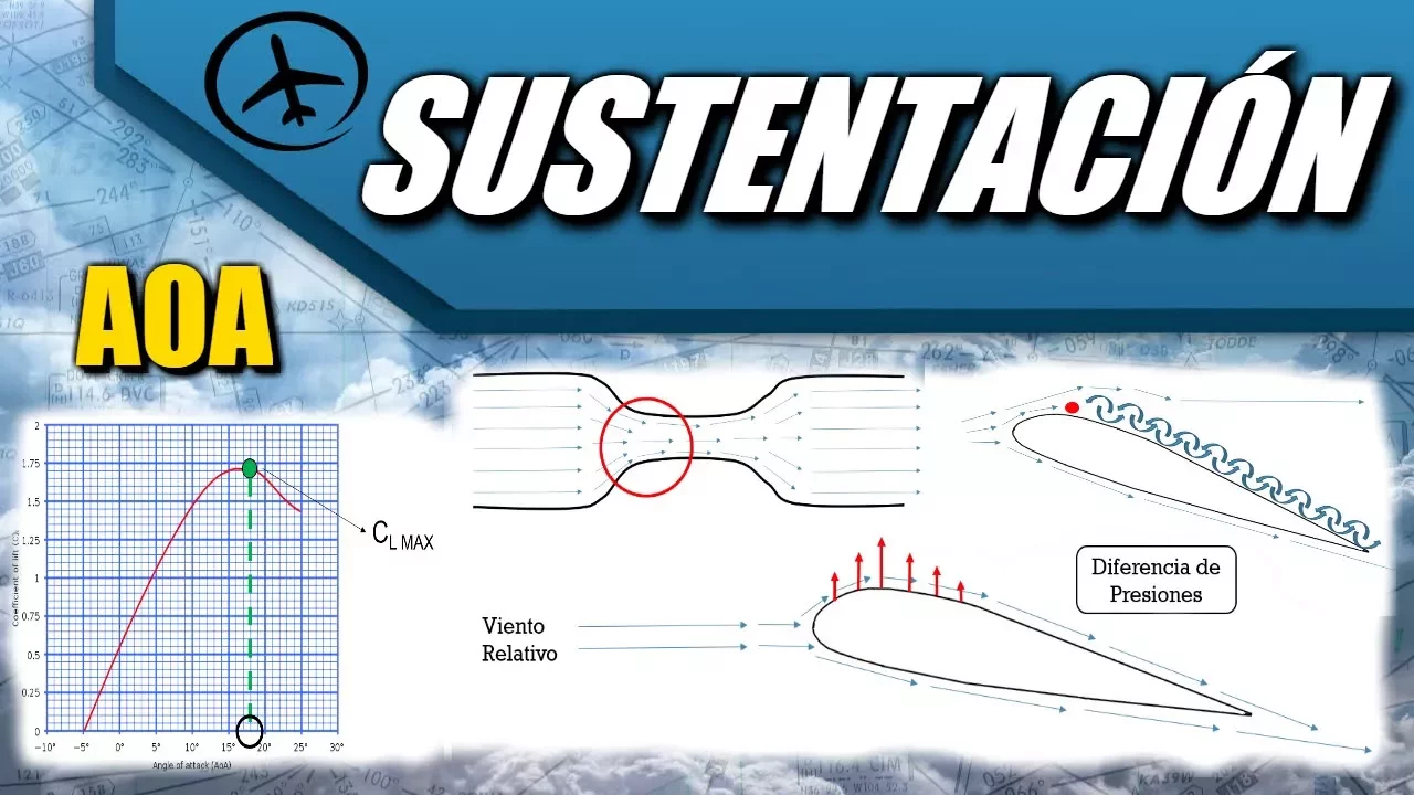



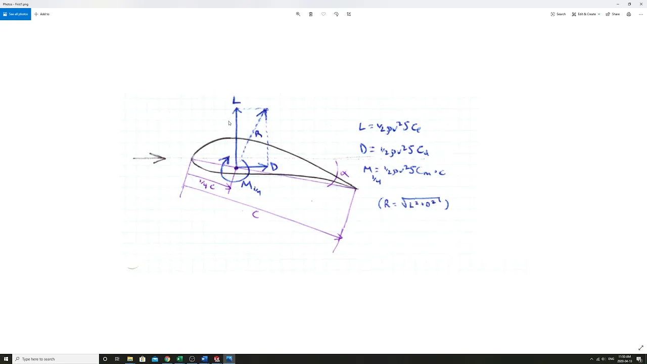
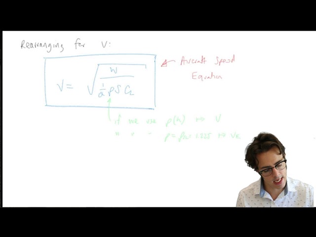
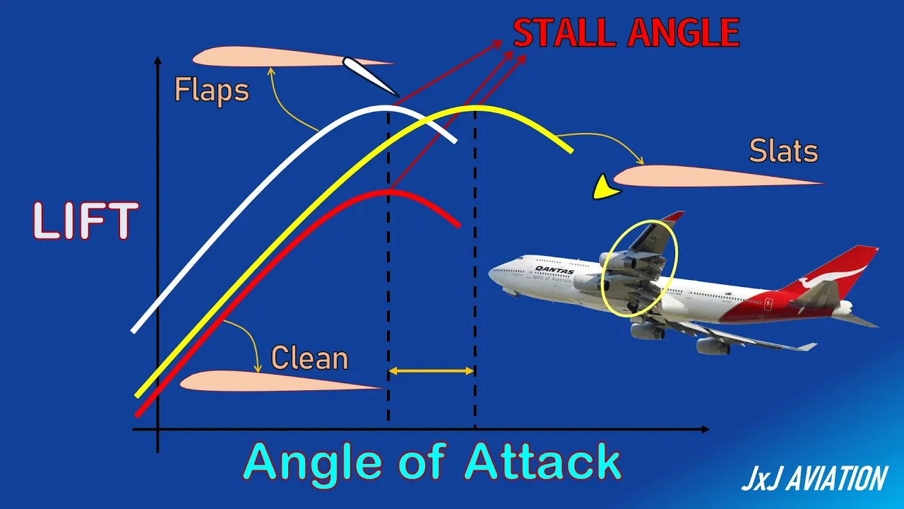
The lift force on an aircraft is calculated using the formula L = ½ρv² × S × CL, where ρ is air density, v is velocity, S is wing area, and CL is the lift coefficient; the lift coefficient depends on the angle of attack, increasing with angle until reaching a critical value beyond which airflow separation causes a stall and dramatic loss of lift.
How to Calculate Lift: Lift Coefficient and Angle of Attack
Added:Basic fluid dynamics, specifically Bernoulli's Principle and how fluid velocity relates to pressure changes.
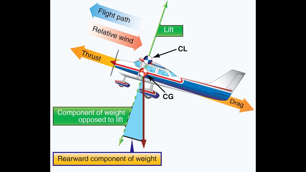
The four fundamental forces of flight (lift, weight, thrust, and drag) and how they balance in steady flight.
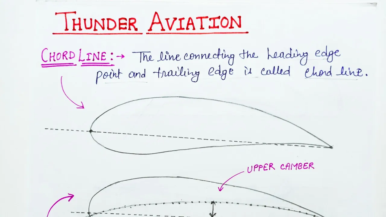
Airfoil geometry terminology, including chord line, camber, relative wind, and the definition of the angle of attack.
Basic algebraic skills necessary to interpret and manipulate equations with multiple variables.
The Drag Coefficient (Cd) and how the Lift-to-Drag (L/D) ratio determines aerodynamic efficiency.
The aerodynamic mechanics of high-lift devices, such as flaps and slats, which temporarily modify wing camber.
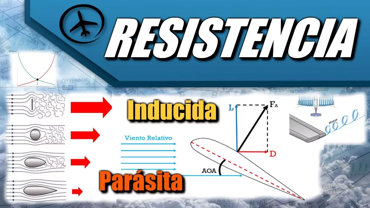
Three-dimensional wing aerodynamics, focusing on induced drag, aspect ratio, and wingtip vortices.
Boundary layer theory and the viscous fluid dynamics that lead to flow separation and stall.
Practical flight mechanics applications, such as calculating minimum stall speed and constructing a flight envelope (V-n diagram).
60K views1.3Klikes12:46Original Release: 2020-05-28
hey guys welcome back to my channel and remember what we learned in the previous video we talked about the forces that act on the aircraft we learned about weight thrust lift and drag but how do you actually define the numerical values of those forces it's easy to find weight because weight is just mass multiplied by gravitational acceleration so mass of the aircraft M multiplied by G which is 9.81 m/s^2 we will learn how to deal with thrust in one of the future videos so in this video we will focus on lift and drag forces we will learn a formula that lets you calculate the numerical value of those forces okay so let's say this is our aircraft and let's just recap from last video what we learned about the four forces that act on the aircraft and this aircraft looks weird but it's okay I hope you get the idea so the easiest force to find would be weight as I already told you it's equal to a mass multiplied by gravitational acceleration the next force is thrust and we will talk about it in more detail in one of the future videos and there's two more aerodynamic forces which are lift and drag and today we will learn how to find their values so it was experimentally determined that lift and drag depend on dynamic pressure and let me write it down and I will denote dependence by this little symbol which means proportional so lift and drag are proportional to dynamic pressure the area of the wing and then the specific coefficients coefficients which are specific for each airfoil these coefficients depend on the type of the airfoil so let's write down the actual formulas and talk about those coefficients in more detail so in order to find lift we multiply dynamic pressure by the area of the wing and by the lift coefficient which is denoted by C subscript capital L and same is true for drag but the difference here is the drag coefficient but now let's write down dynamic pressure in more detail because we know from previous video that it's equal to one half density times velocity squared let's expand this term a little bit one half density velocity squared the area of the wing and there's nothing we can do about the coefficient and let's do the same thing for drag just keep in mind that it's a drag coefficient so now we can use these formulas to find lift and drag forces and their values if we know all of these parameters so where do we find lift and drag coefficients well usually you would need to search the internet to find the lift coefficient of a specific airfoil which are given by a set of numbers and letters which we'll talk about in a future video but generally lift and drag coefficients are measured in the wind tunnel during the testing of the airfoil design and it should be given in the wind tunnel testing report but also you can find these coefficients from the graph of lift coefficient versus angle of attack which we'll talk about a bit later in this video so this is basically what you need to remember about how to find lift and drag forces butt lifts and drag coefficients are the most important from these two formulas because they are as important as Mach and Reynolds numbers and why are these coefficients so important well let's compared to aircraft different in size it's obvious that the larger aircraft will have the larger wing area which will give you more lift and also if the larger aircraft can reach higher speeds so the smaller aircraft cannot generate as much lift as the larger one but does that mean that the smaller aircraft is worse than a larger one not necessarily here is when the lift coefficient plays a big role so let's say for the bigger aircraft the lift coefficient is 0.8 and for the smaller one it's one point one now which aircraft is better here the question should be more which airfoil design is better obviously the higher the lift coefficient the more efficient the lift production is for the aircraft so now we can compare the values for the lift coefficients and say that the second aircraft is more efficient even if it's smaller in size so lifting drag coefficients depend on mark and Reynolds numbers and also the angle of attack of the aircraft and remember we learned what an angle of attack is from one of the very first videos it's the angle alpha between the freestream velocity vector and the cord of the airfoil for all existing aircraft the lift and drag coefficients have been calculated but if you design a new airfoil then you will have to do testing in the wind tunnel to determine these coefficients as I already talked about before a good rule of thumb is that the drag coefficient should be about 10 times smaller than the lift coefficient which makes sense we don't want to create a lot of drag if we create a lot of lift now let's look at how the lift coefficient changes if we change the angle of attack for a given airflow I will draw an approximate graph but I will also insert a picture here of an actual graph so most of those graphs look like this graph here where on the x-axis will have the angle of attack and on the y-axis we have the lift coefficient or CL why do I have alpha here well it's because the lift coefficient depends on the angle of attack as you can see from this graph now what does this dependence tell us let's analyze this graph first we start from zero but for some air Falls this graph is shifted a little bit here or here but for now it's not that important for us so let's say we have this airfoil for which at zero angle of attack we have the lift coefficient equal to zero as well and if you're not new to aerodynamics you should be able to tell me which airfoil gives you a zero lift at zero angle of attack I will leave it as a question below and if you can answer that please answer in the comments so for any airfoil at first we have the lift coefficient grow with the angle of attack so let's say my marker is the airfoil then this position would be angle of attack equal to zero degrees so with growing angle of attack in the x-axis it means that the airfoil is moving upwards like this and the graph tells us that when the airfoil increases the angle of attack we have more or higher lift coefficient or more lift as you can see from here so let's say we increase the angle of attack to 20 degrees and we got some value of 0.7 for the lift coefficient and from here we can calculate the lift force if you remember the formula from the first part of the video now the angle of attack keeps growing and the lift coefficient keeps growing so it's better for the aircraft to be flying at some angle of attack instead of zero but eventually we'll get to some point at which we'll reach the maximum possible lift coefficient now what is this point well let's go down here and let's say this is a critical angle of attack or alpha critical which will give us the maximum value of lift now why is it called critical well because if we increase the angle of attack even more then we will start losing lift and this is a point of no return which is called a stall so if we get into this zone we will completely lose control of the aircraft and we cannot get lift anymore so this is a very dangerous zone into which the aircraft should never get so as you can see from the graph it's better to be flying in this region sometimes we want maximum lift but we should not increase angle of attack more than the critical angle of attack so how can we explain this phenomenon well here we should remember what we learned about viscosity and turbulence remember that at high angles of attack and high velocity the air will not flow perfectly streamlined around the airfoil it will start to separate at some point so the airfoil is now generating lift only in this region this part is now not generating lift so if we increase the angle of attack even more yes sometimes we lose all lift so here we'll have turbulent region and no lift will be generated at this angle of attack so how do we prevent the aircraft from going into this stall region the answer is the safety factor usually the software on board has restrictions on which angle of attack can the pilot reach especially on commercial aircraft for example the maximum could be set to 35 degrees and angle of attack and even if the pilot wants to reach a higher angle of attack he will not be able to because the aircraft will not go into that angle of attack because of the software restriction or limit so I hope this topic was more or less clear to you because it was pretty simple and introductory in the future videos we will go into more detail about the lift coefficients the lift forces and so on so this is it for today thank you so much for watching and leave your questions and comments below my next video will be a little bit different than what we used to because it will be more of an informational video since I get a lot of questions about which textbooks do aerospace engineers use so I will share with you but textbooks that I learned with when I was a student so stay tuned for that and see you in the next video
Up Next
20:08
Wind Tunnel Build Part 2: Airfoil Support, Smoke & Lighting Systems
@DefiantWings
50.2K views•2020-03-20

30:32
Ultrasonic Transducers: Resonant Frequency Measurement and Horn Design
@imajeenyus42
229.9K views•2017-02-22

4:44
Reynolds Number Explained: Laminar vs. Turbulent Flow
@AliyaBurkit
63.1K views•2020-04-23

33:39
How a Student's Question Saved a NYC Skyscraper from Collapse
@veritasium
22.8M views•2025-04-26
Related Study Plans & Knowledge Roadmaps
Structured learning paths in Engineering
engineering
Building Acoustic Levitators: Physics & Arduino
01The Physics of Sound and Standing Waves
02Piezoelectric Transducers and H-Bridge Drivers
03Arduino Programming: Generating 40 kHz Signals
+ 2 more learning modules
14h5 modules
Explore Roadmap
engineering
Building Peltier Cloud Chambers: Particle Tracks
01Cosmic Rays & Cloud Chamber Physics
02Thermoelectric Cooling (TEC) Fundamentals
03Custom Liquid-Cooling Loop Design
+ 2 more learning modules
18h5 modules
Explore Roadmap
engineering
Yagi-Uda Antennas: Modeling, Build & VNA Test
01Introduction to RF and Antenna Fundamentals
02Yagi-Uda Antenna Design Principles
03Antenna Modeling and Simulation in 4NEC2
+ 2 more learning modules
18h5 modules
Explore Roadmap
engineering
ECG Monitor Design: Op-Amps, Filters & Noise
01Electronics & Breadboard Basics
02Op-Amps and Instrumentation Amplifiers
03Bioelectricity and ECG Fundamentals
+ 2 more learning modules
18h5 modules
Explore Roadmap