A solderless breadboard is an essential tool for electronics beginners that allows circuit prototyping without soldering; it features side rails for power distribution and a central prototyping area with rows connected vertically, enabling easy component insertion and removal for testing and experimentation.
How to Use a Breadboard for Beginners and Electronics Projects
Added:Deep Dive
Basic concepts of electricity, including voltage, current, and resistance (Ohm's Law).

MODULO 1- CLASE 1- ELECTRICIDAD BASICA Y ELECTROMAGNETISMO
483
Voltage is electrical potential difference between two points - like height difference creating water pressure. Current flows only when voltage exists between points. Resistance opposes current flow: conductors (copper, silver) have low resistance; insulators (rubber, plastic) have high resistance; semiconductors (silicon) have intermediate conductivity. Ohm's Law states V = I × R, relating voltage, current, and resistance. This fundamental law enables circuit analysis and design.
Click to watch →

Electricity Class 10 concepts
160
Electricity is the flow of charge (protons or electrons), where charge is a property of matter that causes attraction or repulsion; electric current is the rate of charge flow measured in amperes; an electric circuit is a closed path for current flow; resistance is the property that opposes charge flow and decreases its speed; voltage (potential difference) is the difference in charge between two points that drives current flow; and Ohm's Law states that voltage is directly proportional to electric current (V = IR).
Click to watch →

Exam Hack | CIE AS Physics | Structured | Electricity & D.C. Circuits Question
24.4K
Voltage (potential difference) is the energy per unit charge supplied to a circuit. Current is the rate of flow of electric charge through a conductor. Resistance opposes the flow of charge. These three quantities are related by Ohm's Law: V = IR, where V is voltage, I is current, and R is resistance. When voltage increases with constant resistance, current also increases proportionally.
Click to watch →

Basic electrical - Online class EP 1| Voltage| Current| Resistance| Ohms Law| Malayalam| Be Techy|
1.7K
This section covers three fundamental electrical concepts. Voltage is defined as the force applied to a conductor that causes free electrons to flow through it. Electric current is the flow of free electrons in a definite direction through a conductor. Resistance is the opposition offered by a material to the flow of electric current. Conductors allow electrons to flow easily, while insulators offer high opposition to current flow. These concepts form the foundation for understanding electrical circuits and behavior.
Click to watch →

Basic Electrical & Electronics
148
Voltage is the difference in electrical potential between two points, measured in volts, and can be generated through friction, pressure, heat, light, chemical action, or magnetism; current is the rate of electrical charge flow measured in amperes; resistance, measured in ohms, opposes current flow and is affected by material properties, length, cross-sectional area, and temperature; these three quantities are related by Ohm's Law (V = I × R), which allows calculation of any one variable when the other two are known.
Click to watch →
Deep Dive
Understanding of a closed circuit loop and the difference between conductors and insulators.

Intro to Conductivity and Circuits Gizmo Walkthrough
154
This section teaches the difference between open and closed circuits. An open circuit has a gap that prevents charge flow, while a closed circuit allows charges to move freely. Students learn to test materials using an open circuit with a light bulb: if the bulb lights up, the material is a conductor; if not, it's an insulator. The nine materials to test are lead, glass, iron, silver, wood, brass, plastic, copper, and yarn. Students make predictions before testing and explain their reasoning. The section emphasizes that conductors allow electricity to flow while insulators block it, and students should explain why they think materials behave this way.
Click to watch →

Electrical Circuits(ECI) Unit No:-01 Lecture No:01.mp4
12.7K
Conductors are materials that allow electric current to flow easily through them, such as metals (copper, aluminum). Insulators are materials that oppose the flow of electric current, such as plastic, glass, and rubber. The distinction between conductors and insulators is based on their electrical resistance - conductors have low resistance while insulators have high resistance. This classification is fundamental for understanding circuit design and safety.
Click to watch →

Insulators and Conductors- for Kids SC.5.P.11.2
708
A conductor allows energy to pass through it, while an insulator stops or slows down energy from passing through it. A complete circuit requires a closed loop for energy to flow from a battery through wires to a light bulb. To test materials, attach them to a circuit using alligator clips; if the bulb lights up, the material is a conductor. If not, it is an insulator. Common insulators include plastic, rubber, tape, paper, and rubber bands. Common conductors include metal objects like paper clips, pins, knives, and bolts. Some objects contain both conductive and insulating parts (e.g., a pin has metal and plastic). Metals are generally good conductors of electricity.
Click to watch →

Electricity - 04 || Conductors & Insulators || CLASS - X CBSE/ICSE
291
A conductor is a material in which electric charge can flow easily. All metals (copper, silver, gold, aluminum) are good conductors, with silver being the best but expensive. Alloys like nichrome and constantan are also conductors used in heating elements. Electrolytes like salt water and the human body conduct electricity. At the atomic level, conductors have loosely bound outer shell electrons that can be attracted by a positive rod, creating electron deficiency and allowing current flow. Each electron carries 1.6 × 10^-19 coulombs. Two wires are always used in circuits - one carries electrons from negative to positive terminal, the other returns them. For current to flow, one terminal must be positive (electron-deficient) and the other negative (electron-abundant). A closed circuit path is required. An insulator is a material in which electric charge cannot flow easily. In insulators, outer shell electrons are strongly bound to the nucleus by a very strong attractive force, preventing them from being freed. Examples include air, plastic, rubber, wood, and pure water. Insulators do not contain free electrons, which is why current cannot flow through them. Insulators are essential for electrical safety - they cover wires with plastic coating to prevent electric shock and are used in switches to prevent current flow when open.
Click to watch →

PHYSICS-IX-ELECTRICITY-2(02-JUL-2020)
523
Insulators (rubber, plastic, wood) have almost no free electrons and offer high resistance. Conductors (metals, human body) have many free electrons and low resistance. A closed circuit is a complete path where current flows from positive to negative terminal. An open circuit is incomplete, occurring when there's a gap or insulator in the path.
Click to watch →
Deep Dive
Familiarity with basic electronic components like resistors, LEDs, and power sources (batteries).
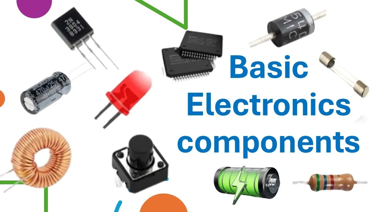
Basic Electronics components | Know about basic Electronics components
273
Basic electronics components are fundamental building blocks of electronic circuits, including resistors (limit current flow, zigzag symbol, measured in Ohms), capacitors (store and release electrical energy, smooth voltage fluctuations, two parallel lines symbol, measured in Farads), transistors (act as switches or amplifiers, two lines with arrow symbol, types include BJT and FET), diodes (allow current flow in one direction only, triangle with line symbol, used for rectification), LEDs (emit light when current flows, diode symbol with light arrows), switches (open or close circuits to control current flow, break in line symbol), batteries (provide DC electrical energy, two parallel lines of unequal length symbol), ground (reference point in circuits, three descending lines symbol), and fuses (protect circuits by breaking connection if too much current flows, line with box symbol).
Click to watch →

basic electronics พื้นฐานอิเล็กทรอนิกส์ ชุดที่ 1
271.4K
Electronics is the fifth factor of modern life, encompassing devices like televisions, refrigerators, radios, VCDs, DVDs, washing machines, and air conditioners. Electronic devices require multiple components including PCBs (printed circuit boards with copper traces), transistors (signal amplifiers/switches), diodes (one-way current flow), capacitors (energy storage), and resistors (current regulation). Electricity is energy that flows through conductors and can be converted to light, sound, or motion. Static electricity (from natural phenomena like lightning) cannot be directly used. Current electricity (flowing through conductors) powers all practical devices. AC (alternating current) reverses direction periodically and powers household appliances (220V). DC (direct current) flows in one direction with constant polarity and powers electronic devices. Batteries provide DC power with specifications including voltage (V) and capacity (mAh). Power supply units convert high-voltage AC (220V) to appropriate DC voltages for electronic circuits. DC circuits require complete paths for current flow from positive to negative terminals. Electronic circuits consist of interconnected components including power sources, switches, and loads. A complete circuit allows current to flow through the load (device being powered). The load converts electrical energy into other forms: light bulbs convert electricity to light and heat, LEDs convert electricity to light, and motors convert electricity to motion. Without a complete circuit, the load cannot function regardless of whether it is connected. LEDs (Light Emitting Diodes) are semiconductor devices that emit light when current flows in the correct direction. They require proper polarity (forward bias) and typically need 2V to operate. LEDs require current-limiting resistors to prevent damage. Different resistor values produce different LED brightness levels: lower resistance allows more current and brighter LEDs, while higher resistance reduces current and dimmer LEDs. Adjustable resistors (potentiometers) allow continuous resistance variation for variable control.
Click to watch →

Embedded Systems and IoT using NodeMCU | Introduction to NodeMCU | Part 1 | GEMLABs
134
Basic electronic components include batteries, LEDs, and resistors. Batteries provide electrical power to electronic devices by storing chemical energy and converting it to electrical energy. LEDs (Light Emitting Diodes) are semiconductor devices that emit light when current flows through them. Resistors control the flow of electrical current in circuits, protecting components and ensuring proper operation.
Click to watch →

Thầy giáo điện tử u80. Bài 1 và Bài 2: cơ bản môn điện tử học, điện trở. Người kể: Vương Khánh Hưng
210
The four fundamental electronic components used in basic circuits are: 1) Capacitors (tụ điện) for energy storage, 2) Power sources (nguồn điện) for providing voltage, 3) Resistors (điện trở) for current control, and 4) LEDs for light emission. These components form the building blocks of electronic circuits.
Click to watch →

IOT и Tinkercad. #2 Основные возможности
277
This section covers essential electronic components used in basic circuits. Resistors control current flow and can be configured with different resistance values and units. LEDs are polarized components with long (anode/positive) and short (cathode/negative) legs that only light up with correct polarity. RGB LEDs combine red, green, and blue channels for multi-color output. Push buttons have two separate contacts for user input. Potentiometers provide variable resistance for adjustable circuits. Batteries supply power with positive and negative terminals requiring correct polarity. Understanding these components forms the foundation for building electronic circuits.
Click to watch →
Deep Dive
How to read simple circuit schematic diagrams and recognize component symbols.
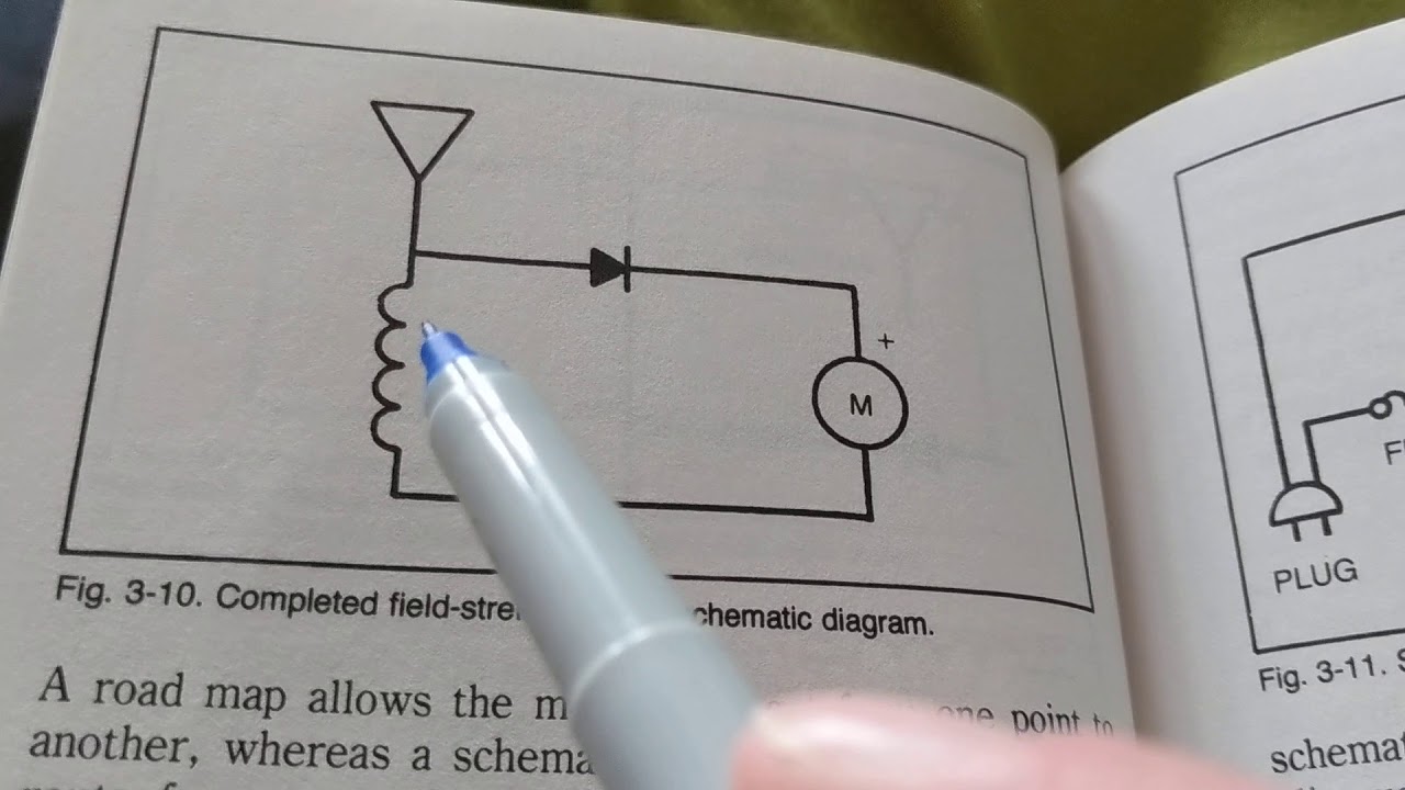
how to read and follow simple BASIC COMPONENTS AND SYMBOLS reading diagrams for BEGINNERS
1.8K
This tutorial teaches beginners how to read and understand basic electronic circuit diagrams by explaining schematic symbols for common components including batteries, bulbs, switches, resistors, capacitors, diodes, transformers, and transistors, while clarifying that schematic diagrams show electrical connections rather than physical wire lengths, and that component values and specifications are typically provided separately from the basic symbol diagrams.
Click to watch →

HOW TO READ SCHEMATICS | Understanding a schematics diagram
2.9K
Schematic diagrams are conceptual maps using standardized symbols to represent electronic components and their connections. While intimidating due to abstract appearance, they follow simple principles. Key components include resistors (squiggly line in NA, realistic in other regions), potentiometers (resistor symbol with arrow), capacitors (parallel plate shape), diodes (basic symbol), LEDs (diode symbol with two arrows), switches, batteries, and ground connections. Understanding these symbols is foundational for reading any electronic schematic.
Click to watch →

Leitura de Componentes Eletrônicos - Simbologia (Prof. Luis Carlos Burgos)
9K
This section teaches how to read electronic schematics using standard symbols. Resistor symbols are rectangles with zigzag lines. Potentiometers have three terminals with an adjustment line. Capacitor symbols vary: electrolytic capacitors have lines of different thickness (polarized), while common capacitors have equal lines. Variable capacitors have an arrow indicating adjustability. Diodes and LEDs have triangle symbols with lines, with LEDs adding light-emitting circles. Transistors show three terminals with arrows indicating NPN or PNP types. Coils are simple zigzag lines, transformers have multiple windings. Integrated circuits appear as rectangles or triangles. Fuses are simple lines with gaps. Power symbols include positive bus (arrow line) and ground (triangle pointing down).
Click to watch →
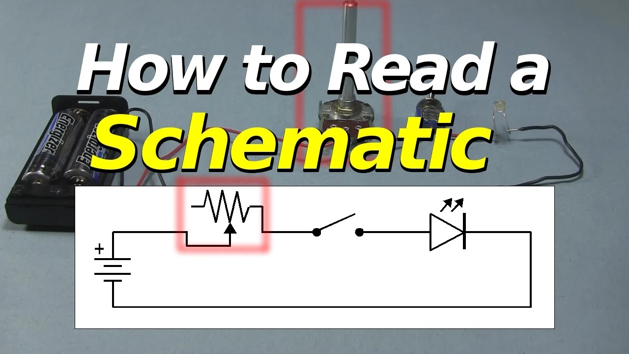
How to Read a Schematic: Electronics Circuit Symbols Explained
992.9K
This comprehensive lesson covers the essential skills for reading electronic schematics. Key concepts include understanding the difference between schematics (using standardized symbols) and wiring diagrams (using pictures). Students learn to identify fundamental components: batteries (long line = positive), resistors (zigzag or rectangle), switches (open/closed line breaks), LEDs (diode symbol with arrows), and various ground types (earth ground with three lines, chassis ground for vehicles). The lesson emphasizes that learning schematic symbols is foundational, as most electronics work involves recognizing these standardized representations.
Click to watch →
How to read Electrical Wiring Diagrams Series (6 of 8)
2K
This comprehensive section covers the foundational concepts of learning to read and draw schematic diagrams. Two schools of thought exist: learning to read before drawing, or learning to read as part of the drawing process. Both approaches have merits, and the recommended method combines them—learning basic component symbols first, then practicing reading many schematics, and finally drawing your own. Three basic symbols are essential: electrochemical cell (power source), conductors (straight solid black lines), and light bulb. The cell symbol represents the heart of the circuit as it supplies all power. Each component receives an alphabetic-numeric designation where letters indicate type (T for transformer, D for diode, C for capacitor, R for resistor, F for fuse, P for plug) and numbers reference position/order in the components list. Standard abbreviations include D for most diodes, SR for silicon rectifier, ZD for zener diodes. Conflicts arise when abbreviations conflict with common usage (relay cannot use R because it indicates resistor; crystal cannot use C because it indicates capacitor). Standard diagramming practice requires including letter and number even if only one of a certain component type exists.
Click to watch →
Prerequisite Knowledge
- Concept 01Basic concepts of electricity, including voltage, current, and resistance (Ohm's Law).
- Concept 02Understanding of a closed circuit loop and the difference between conductors and insulators.
- Concept 03Familiarity with basic electronic components like resistors, LEDs, and power sources (batteries).
- Concept 04How to read simple circuit schematic diagrams and recognize component symbols.
Subsequent Learning
- Step 01How to use a digital multimeter to measure voltage, current, and continuity within a breadboard circuit.
- Step 02Interfacing breadboards with programmable microcontrollers like Arduino or Raspberry Pi for interactive projects.
- Step 03Integrating more advanced electronic components such as transistors, capacitors, and Integrated Circuit (IC) chips.
- Step 04Transitioning temporary breadboard designs into permanent circuits using soldering, stripboards, or custom Printed Circuit Board (PCB) design.
Basics
LED Circuit
Basics
0:05Playing Section
- 1
Explains breadboard structure: power rails and prototyping rows, vertical connections.
- 2
Covers tool varieties: sizes, colors, and the central gap for ICs.
- 3
Highlights adhesive backing for stability during circuit assembly.
The Case for Soldering and Perfboard Prototyping over Solderless Breadboards
While solderless breadboards are praised for their ease of use, experienced makers and educators argue they can hinder beginners by introducing frustrating, hard-to-diagnose issues. Solderless connections are prone to loose contacts, high resistance, and parasitic capacitance, which often cause circuits to behave erratically—especially at higher frequencies or with sensitive components. Proponents of alternative methods suggest that starting with perfboards (stripboards) and basic soldering, or utilizing software circuit simulators (like SPICE), is a superior approach. Soldering teaches a foundational, permanent skill and ensures robust electrical connections, eliminating the 'ghost' hardware bugs common to breadboards. Meanwhile, software simulation allows beginners to understand circuit theory in a controlled environment without the physical noise and connection failures inherent to solderless breadboarding, ultimately leading to a less discouraging learning experience.
Deep Dive
How to use a digital multimeter to measure voltage, current, and continuity within a breadboard circuit.
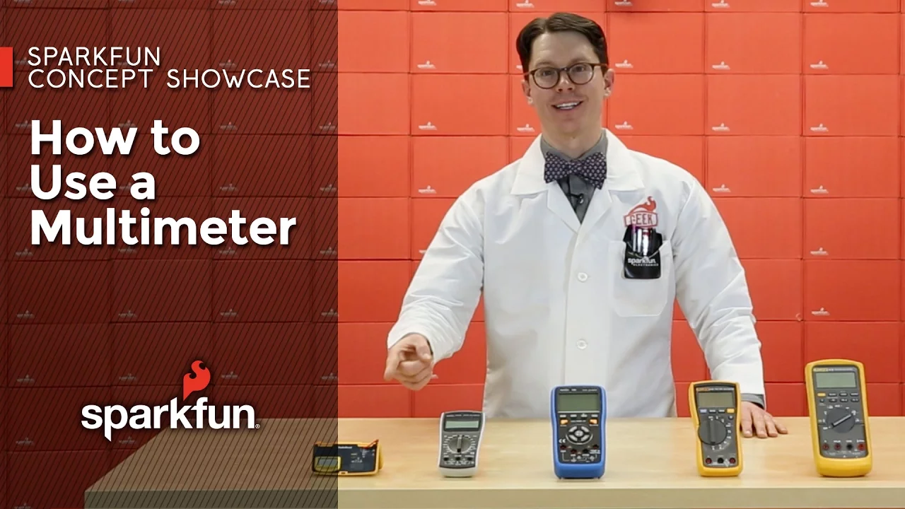
Multimeter Fundamentals: Voltage, Current, Resistance
571.9K
A digital multimeter (DMM) is an essential tool for electronics testing that measures voltage, current, resistance, and continuity; to measure voltage, connect the meter in parallel with the component and select the appropriate DC or AC range; to measure resistance, disconnect the component from any power source and connect the meter in parallel; to measure current, the meter must be placed in series with the circuit, requiring the probe to be moved to a dedicated current port; and for diode and continuity testing, the meter beeps when points are electrically connected or displays the forward voltage drop across a diode.
Click to watch →
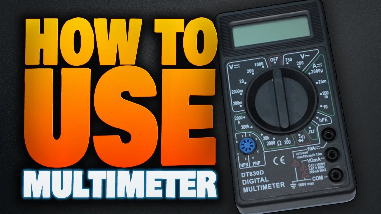
DT-830B :// How to use a Digital Multimeter to test Voltage,Current and Resistance
229.1K
Current measurement requires moving the red lead to the 10A socket and setting the knob to amps. Connect the multimeter in series between the power source and load by attaching the positive cable first, then connecting the red lead to the negative cable. The meter displays the current draw (e.g., 0.75A for a TV). Basic multimeters lack continuity beep functions but show brief spikes when leads touch both ends of a conductor. LED polarity testing uses diode mode—correct polarity causes illumination, reversed connections show nothing.
Click to watch →

How to Use a Multimeter (Voltage, Current, Resistance)
159
A digital multimeter measures electrical properties by connecting leads in specific configurations: for voltage measurements, place the meter in parallel with the component and select DC voltage mode with correct polarity; for current measurements, place the meter in series with the circuit and select the appropriate current range; for resistance measurements, disconnect power and at least one leg of the circuit to avoid parallel paths; for continuity testing, the meter beeps when a complete path exists; for diode testing, forward bias shows a voltage drop while reverse bias shows open circuit; for capacitor testing, connect with correct polarity to measure capacitance; and for AC measurements, select AC voltage or frequency modes to measure household power and signal characteristics.
Click to watch →
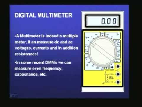
Lecture - 1 Introduction to Basic Electronics
2.1M
Digital multimeters verify breadboard connectivity by measuring resistance between points. Zero resistance indicates continuity (electrical connection exists), while infinite resistance indicates an open circuit. This technique ensures proper breadboard operation before building circuits. The multimeter's continuity function provides audible alerts when zero resistance is detected, simplifying verification procedures for electronics students learning circuit construction techniques.
Click to watch →

How to use a Multimeter Voltage Current and Continuity testing
113.1K
A multimeter is a versatile electronic testing tool that measures voltage (using black and red leads with appropriate range settings for DC or AC), current (requiring the circuit to be broken and the positive lead moved to the 10A slot), and continuity (testing if a circuit is complete by checking resistance and listening for a beep); key safety practices include never measuring current without breaking the circuit and exercising caution when testing household current.
Click to watch →
Deep Dive
Interfacing breadboards with programmable microcontrollers like Arduino or Raspberry Pi for interactive projects.

Free Virtualization Clusters and Breadboards, Hak5 1718
26K
Breadboards enable rapid electronic prototyping using internal conductive clips organized into bus strips (for power distribution with separate positive and negative rails) and socket strips (for component connections with horizontal electrical connectivity). Components like resistors limit current flow, protecting sensitive devices like LEDs. Arduino programming involves defining pins as inputs (detecting events like button presses using digitalRead()) or outputs (controlling devices using digitalWrite()). Conditional logic enables responsive behavior where outputs change based on sensor input. Wire color coding helps organize complex circuits. This foundation enables building interactive electronic projects combining microcontrollers, sensors, and actuators for applications ranging from simple LED blinking to sophisticated IoT devices.
Click to watch →
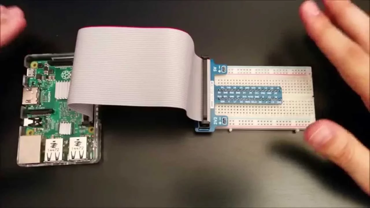
Conectar la placa de prototipado a la Raspberry Pi
4.1K
To connect a breadboard to a Raspberry Pi, align the red-marked pin 1 of the breadboard with the GPIO expansion board's connector, ensuring the plastic tab aligns with the breadboard's frame hole, then connect the expansion board to the breadboard's central female connectors; the breadboard features power rails (+ and -) for voltage distribution, a central area with lettered columns and numbered rows for component connections, and three power rails (3.3V, 5V, and ground) that provide reference voltages for circuit prototyping, with 3.3V being the recommended voltage for GPIO connections to prevent damage to the microprocessor.
Click to watch →
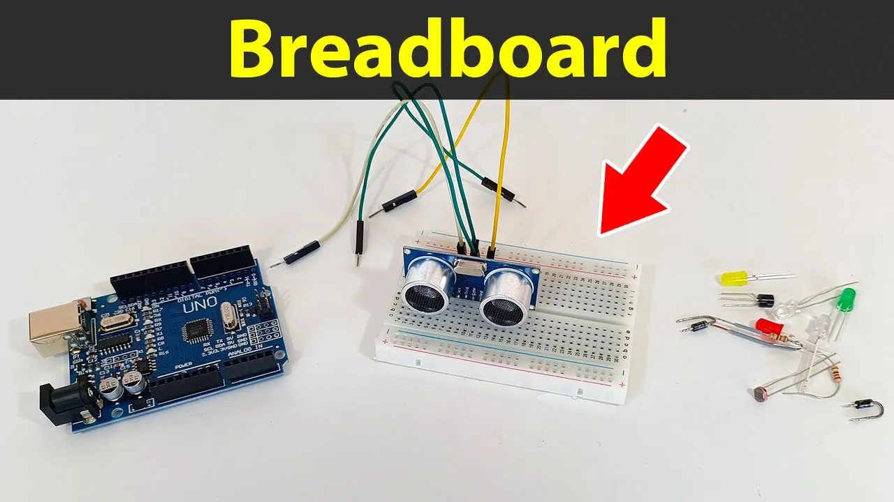
Aprender como usar e uma placa breadboard e montar componentes eletrónicos com o Arduino
243
A breadboard is a prototyping board for electronics projects using Arduino and Raspberry Pi. The 400-point breadboard is the most common size, though smaller (half size) and larger (double size) versions are also available. All breadboards follow the same standard spacing between pins, regardless of size.
Click to watch →
#1 Say NO to ARDUINO! New ARM STM32 Microcontroller Programming and Circuit Building Series
166.3K
Microcontrollers can be broken out into pins that can be plugged into breadboards for prototyping electronics. Breadboards are used for developing circuits on the actual breadboard with discrete components, taking advantage of the microcontroller's pins. A minimal circuit board can contain only the microcontroller with pins broken out, allowing designers to create circuits specifically for particular chips and then add components around the microcontroller in PCB design software.
Click to watch →
Smart Farming Competition PART 2 (Microcontrollers)
126
Digital devices can only be on or off (zero or one), while analog devices can be adjusted between extremes. For digital devices, use digitalRead() and digitalWrite(). For analog devices, use analogRead() and analogWrite(). To connect an LED: connect the longer pin (anode/positive) to a digital pin through a 100-500 ohm resistor, and the shorter pin (cathode/negative) to ground. The resistor reduces voltage from 5V to 1.7V (LED operating voltage) using Ohm's law (V=IR). Breadboards enable circuit prototyping without soldering: vertical lines represent single connection points, horizontal lines represent different points. Components connected to the same vertical line share that connection point, allowing easy testing and modification. A simple LED blinking program: pinMode(2, OUTPUT) configures pin 2 as output; in loop(): digitalWrite(2, HIGH) turns LED on, delay(1000) waits 1 second, digitalWrite(2, LOW) turns LED off, delay(1000) waits 1 second. Delays are necessary because Arduino executes thousands of instructions per millisecond.
Click to watch →
Deep Dive
Integrating more advanced electronic components such as transistors, capacitors, and Integrated Circuit (IC) chips.

Komponen Elektronika
142
Electronic components are basic elements made from specific materials that form circuits in electronic devices. They are classified into active components (require external current to operate, such as diodes, transistors, and ICs) and passive components (do not require external current, such as resistors, capacitors, and inductors). Transistors are fundamental active components with three terminals (collector, emitter, base) and come in NPN and PNP types. NPN transistors conduct current from collector to emitter when positive current is applied to the base, while PNP transistors conduct from emitter to collector when negative current is applied. Before transistors, computers used vacuum tubes the size of water bottles, requiring thousands per device. In the 1960s, William Shockley developed smaller transistors (0.5cm × 0.5cm), dramatically reducing computer size while increasing capacity. Integrated Circuits (ICs) integrate millions of transistors, resistors, and other components into a single chip, classified as analog ICs (operating on continuous signals) or digital ICs (processing binary 0s and 1s).
Click to watch →

MPPSC 2020 Computers & ICT| Electronics Part-2 | Manya Education
5K
Integrated circuits (ICs), also known as chips, are advanced electronic components that contain multiple electronic components (transistors, resistors, capacitors) fabricated on a single semiconductor chip. ICs were introduced in the third generation of computers and are used in amplifiers, timers, microprocessors, and computer memory. They are made of silicon and can contain hundreds of millions of transistors, enabling the creation of complex electronic circuits in very small spaces.
Click to watch →
සංගෘහිත පරිපථ | Integrated Circuit | Advanced Level Physics | Wisdomscape
321
Integrated circuits (ICs) are electronic components that combine multiple electronic components such as transistors, resistors, and capacitors onto a single semiconductor chip, enabling complex electronic functions in compact devices. They are fundamental building blocks in modern electronics, used in applications ranging from computers and smartphones to medical devices and automotive systems.
Click to watch →
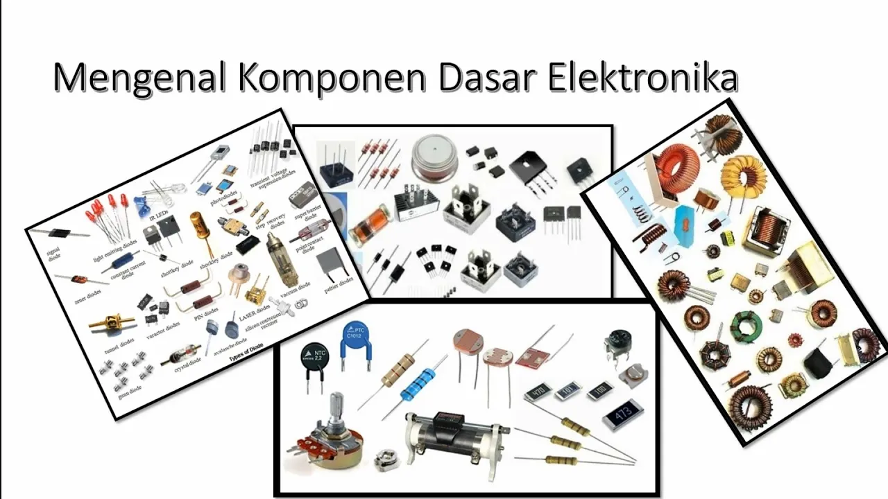
MENGENAL KOMPONEN DASAR ELEKTRONIKA! Part 2
25.2K
Transistors are active electronic components serving multiple functions including current amplification, switching, voltage stabilization, and signal modulation. They have three terminals (base, emitter, collector) and come in PNP (positive-negative-positive) and NPN (negative-positive-negative) types. Integrated Circuits (ICs) represent the pinnacle of electronic miniaturization, containing hundreds to millions of transistors, resistors, and other components in a single package. ICs serve as the 'brain' in electronic devices, performing functions from amplification to complex data processing. A microprocessor, for example, can contain millions of transistors. ICs are semiconductor components highly sensitive to electrostatic discharge, requiring careful handling during assembly and use.
Click to watch →

ما هو IC ? - الجزء الأول
193.6K
Integrated circuits contain multiple electronic components including resistors (المقاومات), capacitors (المكثفات), and transistors (الترانزسترات), along with other electronic elements. These components are integrated together on a single electronic chip.
Click to watch →
Deep Dive
Transitioning temporary breadboard designs into permanent circuits using soldering, stripboards, or custom Printed Circuit Board (PCB) design.
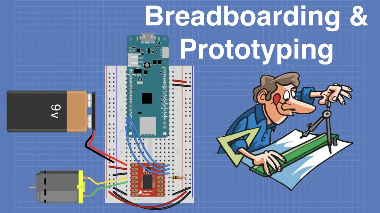
Breadboarding & Prototyping for Electronics, Arduino & Raspberry Pi
132K
Successful prototypes transition from breadboard to permanent construction using perfboard or printed circuit boards. Perfboard serves as an intermediate step for testing layouts and making modifications before PCB fabrication. Quality perfboard uses glass epoxy with plated-through holes for reliable connections. IC sockets enable easy component replacement. Wire gauge selection (wire wrap for signals, 22 AWG for power) ensures proper current handling. Perfboard experience informs PCB layout decisions.
Click to watch →

How To Build Circuits On Stripboard or Veroboard
126.9K
This tutorial demonstrates how to construct a 555 timer-based LED flasher circuit on stripboard (veroboard), covering essential skills including board cutting, component placement, soldering techniques, track cutting, and circuit troubleshooting using a multimeter.
Click to watch →

How to Make a Circuit Board (Beginner's Guide)
368.8K
This comprehensive section covers the transition from temporary prototyping to permanent circuit construction and professional manufacturing. It details perf board assembly techniques including cutting methods, lead bending, and soldering procedures using appropriate equipment and safety precautions. The progression continues into professional PCB design using KiCad EDA software, explaining how to recreate circuits digitally with customizable board shapes, component placements, and solder pad configurations. The final stage covers the PCB manufacturing process through services like JLCPCB, including file preparation (BOM and part orientation files), customization options, assembly services, and order tracking. This workflow enables hobbyists to transform experimental circuits into production-ready electronic products.
Click to watch →
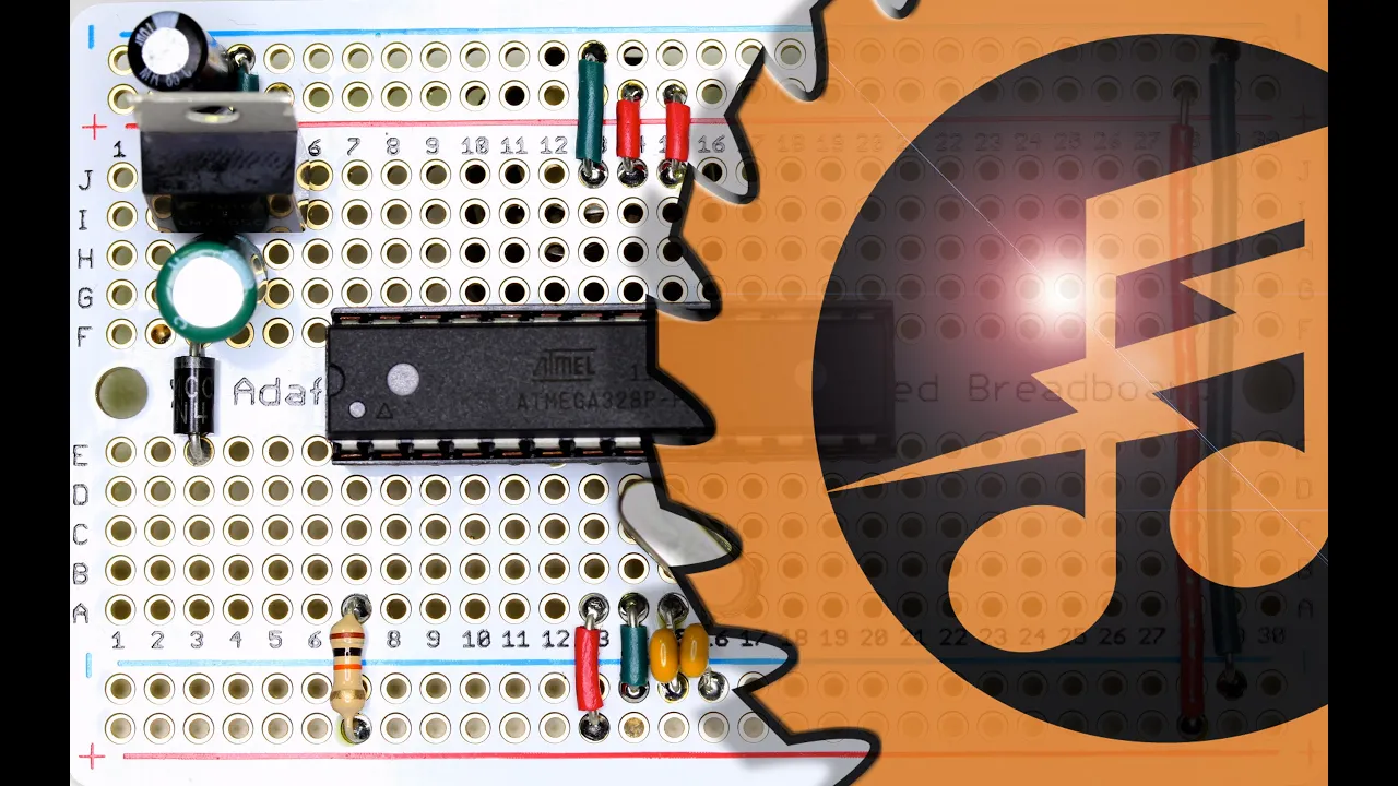
Arduino on a Proto-Board - Make it permanent!
132.2K
This video demonstrates how to convert a working Arduino circuit from a breadboard to a permanent soldered version using a proto-board, covering essential steps including transferring components to matching locations, soldering parts in place, adding power regulation with a 7805 voltage regulator and filtering capacitors, installing a crystal oscillator and decoupling capacitors, and properly connecting the power supply with correct polarity to create a durable, enclosed circuit that can run Arduino code indefinitely.
Click to watch →
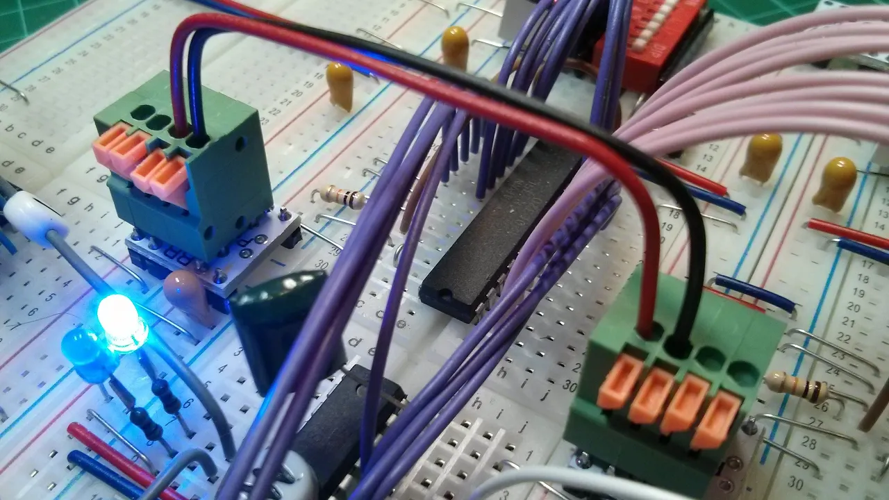
New PCBs from JLCPCB - Breadboard Power Distribution
26.7K
Breadboard computers suffer from poor power distribution due to unreliable breadboard links. The solution is a PCB link board that replaces multiple breadboard connections by linking positive to positive and negative to negative across panels. The board also bridges power busses together and includes pads for additional power connectors. Installation involves soldering DuPont headers in pairs, with careful alignment needed due to breadboard warping. The PCB design is ambidextrous and can be oriented either way.
Click to watch →
Basics
LED Circuit
Basics
0:05- 1
Explains breadboard structure: power rails and prototyping rows, vertical connections.
- 2
Covers tool varieties: sizes, colors, and the central gap for ICs.
- 3
Highlights adhesive backing for stability during circuit assembly.
The Case for Soldering and Perfboard Prototyping over Solderless Breadboards
While solderless breadboards are praised for their ease of use, experienced makers and educators argue they can hinder beginners by introducing frustrating, hard-to-diagnose issues. Solderless connections are prone to loose contacts, high resistance, and parasitic capacitance, which often cause circuits to behave erratically—especially at higher frequencies or with sensitive components. Proponents of alternative methods suggest that starting with perfboards (stripboards) and basic soldering, or utilizing software circuit simulators (like SPICE), is a superior approach. Soldering teaches a foundational, permanent skill and ensures robust electrical connections, eliminating the 'ghost' hardware bugs common to breadboards. Meanwhile, software simulation allows beginners to understand circuit theory in a controlled environment without the physical noise and connection failures inherent to solderless breadboarding, ultimately leading to a less discouraging learning experience.
Basic concepts of electricity, including voltage, current, and resistance (Ohm's Law).
Understanding of a closed circuit loop and the difference between conductors and insulators.
Familiarity with basic electronic components like resistors, LEDs, and power sources (batteries).
How to read simple circuit schematic diagrams and recognize component symbols.
How to use a digital multimeter to measure voltage, current, and continuity within a breadboard circuit.
Interfacing breadboards with programmable microcontrollers like Arduino or Raspberry Pi for interactive projects.
Integrating more advanced electronic components such as transistors, capacitors, and Integrated Circuit (IC) chips.
Transitioning temporary breadboard designs into permanent circuits using soldering, stripboards, or custom Printed Circuit Board (PCB) design.
49.6K views456likes3:41@LiveSparksOriginal Release: 2015-06-29
hey youtube Ravi here so, if you are just getting started into electronics then soldering is probably not what you wanna get into on your first date that's where the solderless breadboard comes in. Let's see how to use it.
This is generally how all the breadboards look like.
They come in different sizes and colours but they work in the same way.
All breadboard s have generally two parts There are the side rails on both sides which are your power lines they are connected horizontally all along the breadboard and there is the middle part which is your prototyping space these rows are connected vertically though not along the middle gap.
This grove is where you put an IC (Integrated Circuit) This breadboard is a 800 point breadboard i.e. there are 800 points or holes to put your components in. These holes are just the right size to accommodate wires LED's for other components.
Generally the back of the breadboard has double-sided tape so that you can stick them to a surface to keep them from slipping or moving around while making connections or changing components.
With that heavenly knowledge aside, let's make a simple circuit and what's better than turning on an LED.
You'll need a breadboard, a LED (of course) I'm using a 5mm white LED A 100 ohm resistor and some wires I'll be using breadboard jumper wires but you can use any normal wires just stripped at the ends and finally a power source you can use anything for this a battery or an arduino or Raspberry Pi but I prefer this.
This is a breadboard power supply it cost less than a dollar and is really handy and easy to use while working with a breadboard. You can even power an arduino with it using the USB port. So let's get to the circuit.
Put one end of the 100 ohm resistor in the positive power rail of the breadboard and the other one in any row you like.
Put the positive end of the LED i.e. the longer lead of the LED in the same row as the resistor and the negative end in a adjacent row.
DON'T PUT BOTH THE ENDS OF THE LED IN THE SAME ROW!!!
Now take a wire and put it's one end in the row with the negative lead of the LED put the other end in the ground rail of the breadboard Let's turn the circuit on.
And...... It works!
Simple as that we have made a working and reliable circuit without soldering or twisting any wires.
The beauty of using a breadboard is that if you wanna replace a component you can just take it out put in another one without disturbing the rest of the circuit so you see breadboard is a must-have if you are into electronics and you want to test circuits or try out then breadboard is a really handy component for example in this circuit if I wanna replace an LED because just I don't like the colour, I can simply do so without disturbing the rest of it.
if the resistor burnt out or you wanna try a lower value you that is easy to replace too Thanks for Watching!!
Drop a like if you liked it, Suscribe for More. See you in the next one!!
Up Next
4:52
How to Read a Schematic: Electronics Circuit Symbols Explained
@RimstarOrg
992.9K views•2014-07-03

12:54
Triumph of Orthodoxy Icon: Byzantine Art & History Explained
@BenCallan
2.1K views•2024-08-06

9:49
FastAPI vs Flask vs Django: Choosing the Right Python Web Framework
@TechWithTim
302.5K views•2024-05-26

1:42
Game of Thrones Opening Credits: A Cinematic Analysis
@gameofthrones
46.3M views•2011-04-18
Related Study Plans & Knowledge Roadmaps
Structured learning paths in General & Interdisciplinary Studies
general-studies
Elevator Engineering: History, Physics & Cities
01From Hoists to Safety Brakes: The Dawn of Vertical Lift
02Hydraulic vs. Traction: The Engineering Physics of Elevators
03Modern Speed, Safety, and Algorithms
+ 2 more learning modules
12h5 modules
Explore Roadmap
general-studies
Rubber: Material Science, History & Geopolitics
01Origins of Natural Rubber & Mesoamerican History
02The Chemistry of Natural Rubber & Vulcanization
03The Geopolitics of the Rubber Boom & Colonization
+ 2 more learning modules
12h5 modules
Explore Roadmap
general-studies
Containerization: Evolution, Logistics & Trade
01Ancient Trade & Bulk Cargo: Amphorae to Barrels
02The Industrial Revolution & Cardboard Packaging
03The Containerization Revolution: Malcom McLean
+ 2 more learning modules
12h5 modules
Explore Roadmap
general-studies
Textile Tech: Evolution, Labor & Global Impact
01Pre-Industrial Textiles: Handloom & Cottage Industry
02Mechanization: The Spinning Jenny to the Power Loom
03The Factory System & Global Labor Transformation
+ 2 more learning modules
10h5 modules
Explore Roadmap