







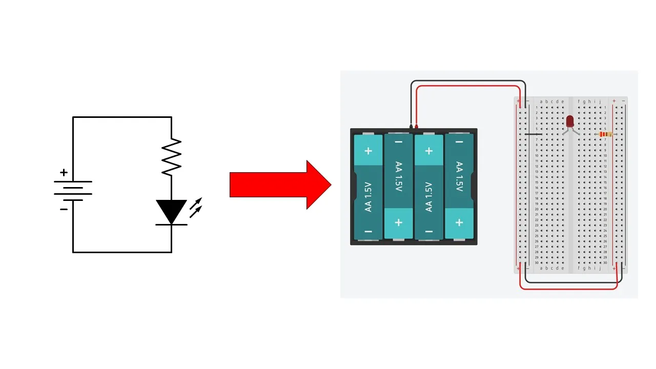













A schematic is a standardized diagram using specific symbols to represent electronic components (like batteries, resistors, switches, LEDs, capacitors, and diodes) and their connections, where crossed lines without dots indicate no connection while dots show connections, and ground symbols (earth ground or chassis ground) simplify complex wiring by representing shared reference points.
How to Read a Schematic: Electronics Circuit Symbols Explained
Added:Basic concepts of electricity, including voltage (V), current (I), and resistance (R).
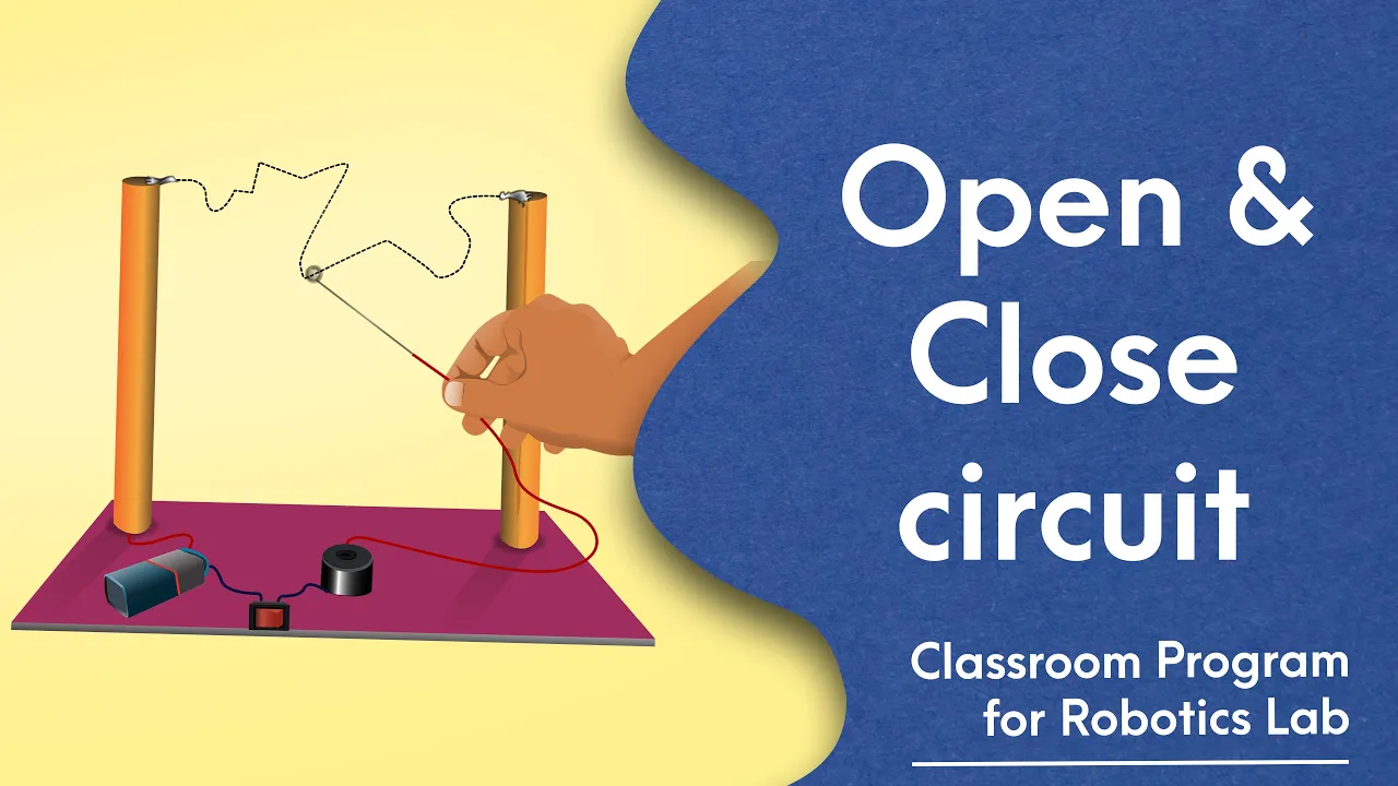
The concept of a closed loop or complete electrical circuit where current can flow.
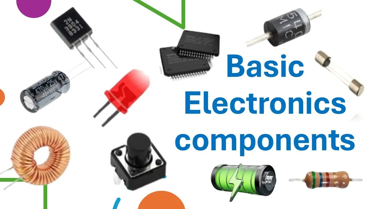
Familiarity with common physical electronic components (like batteries, resistors, and LEDs) to connect real-world objects to their abstract symbols.
The distinction between Direct Current (DC) and Alternating Current (AC) power sources.
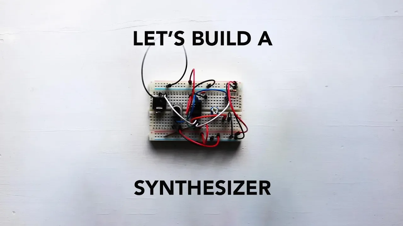
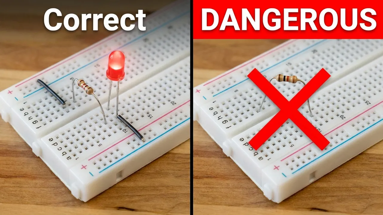
How to build physical circuits on a breadboard using a schematic diagram as a guide.
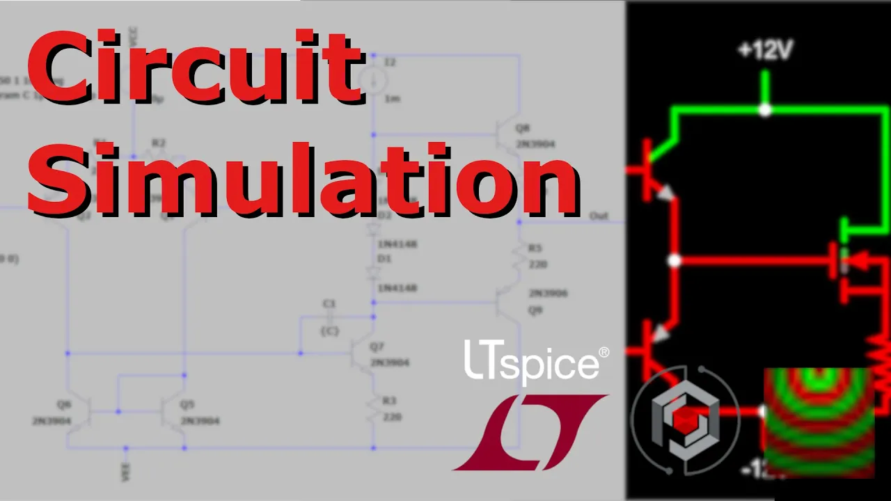
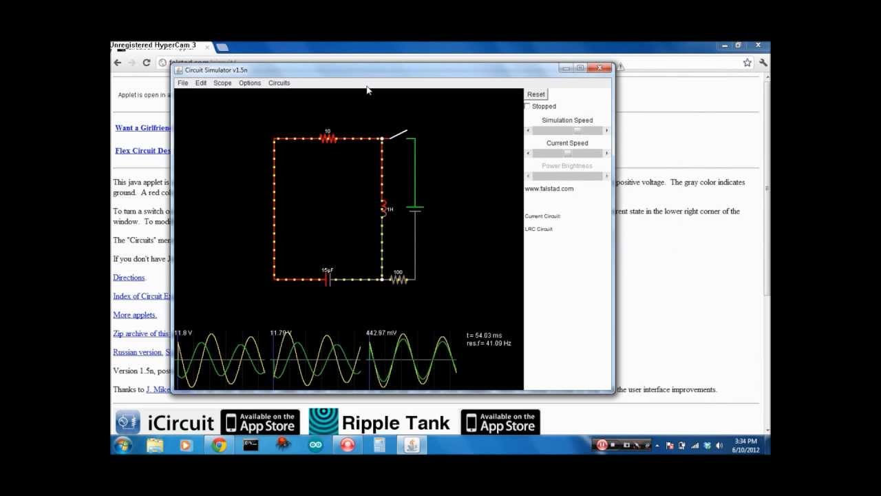
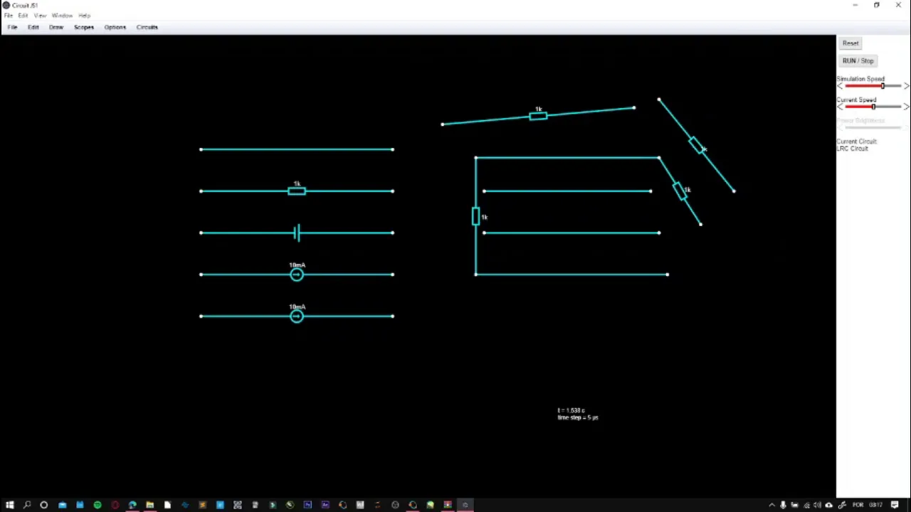
Using circuit simulation software (such as LTspice or Falstad) to model and test schematics digitally.
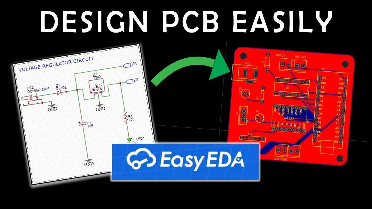
Introduction to Printed Circuit Board (PCB) design software (like KiCad or EasyEDA) to translate schematics into physical board layouts.
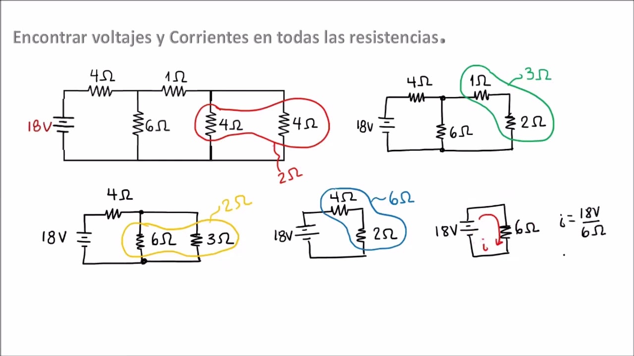
Advanced circuit analysis laws, such as Kirchhoff's Voltage and Current Laws (KVL/KCL).
Using diagnostic tools like multimeters and oscilloscopes to troubleshoot physical circuits against their schematic representations.
992.9K views20.6Klikes4:52Original Release: 2014-07-03
hi gang I'm going to give you the basics on how to read a schematic for anyone new to electronics if you're experienced with schematics and you have any helpful tips for beginners please feel free to leave them in the comments below what do I mean by schematic to keep things simple for people new to electronics often I'll draw a circuit like this with little pictures or photos of the parts and different colored lines this is called a wiring diagram however a schematic would look like this drawn with specific symbols and not always laid out like the final circuit that's what you'll see most of the time let's start with a very simple circuit there's some batteries a resistor an onoff switch and an LED and of course there are also the wires connecting it all together we flip the switch to the on position and the LED lights up here's the schematic for it you can see that different symbols represent different parts on the circuit this is the symbol for a battery or a One battery cell if the battery has more than one cell then you'd simp have more of them Drawn Together the longer line is the positive side of the battery most batteries have a marking on them indicating which terminal is positive and or negative in North America the symbol for the resistor is a zigzag line like this the international standard is to draw it as a rectangle like this the onoff switch is drawn like this here it's drawn open or off if we're closed or on then it would look like this the symbol for the LED looks like this it's a symbol for a diode but with arrows representing light being being emitted from it that makes sense since LED stands for light emitting diode so a big part of learning to read schematics is learning the symbols and though there are a lot of them you mostly use only a handful another part to schematics is the lines representing the wiring the schematic can get so complicated that lines have to cross each other this happens with my crystal radio amplifier number here's the schematic for it if the lines cross each other like this or this or this then they're not connected if the lines are supposed to be connected then a DOT will be drawn at the intersection there is a way to simplify the lines and that makes use of a symbol like this this means Earth ground and is negative notice that all these lines eventually end up at the Earth ground and in fact they do there're these wires in the actual breadboard and here they are all soldered together in the back instead of drawing all those lines going to the one ground symbol we can just draw in the ground symbol wherever needed and it'll be understood that all those lines end up at the same ground there are other types of grounds too for example in a car the negative of the battery and the negative of a lot of the electrical components are connected to the car's chassis that's called the chassis ground and has this symbol this is a diode it allows current to flow in One Direction only this direction the negative side is this side if you're used to thinking in terms of electrons which are negative the electrons flow in this direction against the arrow conventional current is in the opposite direction since that's the flow of positive charge so conventional current flows in the direction of the arrow notice that the line next to the arrow corresponds to the line drawn near one end of the actual diode this is a resistor that you can adjust called a potentiometer in my crystal radio amplifier I use it to adjust the volume it symbol is the same as a resistor with a fixed value like in our simple circuit but with an arrow pointing to it remember that in the international standard a rectangle is used for the resistor so the potentiometer looks like this we can replace the fixed value resistor in our simple circuit with the potentiometer since we're replacing just one resistor we connect to the middle and one of the ends and leave the other end unconnected that allows us to adjust the brightness of the light notice that this circuit also has some capacitors this symbol is for capacitors that have a positive side and a negative side what are called polarized capacitors for example electrolytic capacitors are polarized capacitors they usually have a stripe drawn on one side like this or a minus sign or both but not all capacitors have positive and negative sides the symbol here is for a non-polarized capacitor just two straight lines these capacitors come in many shapes and sizes and don't have any minus signs on them and that should get you started on reading schematics for more symbols see this web page on my website well thanks for watching see my YouTube channel rimstarorg for more videos like this that includes one showing my crystal radio amplifier in action along with step-by-step instructions to make your own another showing how to make a jewel thief circuit that powers a compact fluorescent light bulb and one showing my music player based on a 555 timer chip circuit and don't forget to subscribe if you like these videos or give a thumbs up or leave a question or comment below see you soon
Up Next

7:46
Medical Electrical Safety: IEC 60601 Standards Explained
@BiomedicalEngineersTV
42.3K views•2020-07-09

12:54
Triumph of Orthodoxy Icon: Byzantine Art & History Explained
@BenCallan
2.1K views•2024-08-06

9:49
FastAPI vs Flask vs Django: Choosing the Right Python Web Framework
@TechWithTim
302.5K views•2024-05-26

1:42
Game of Thrones Opening Credits: A Cinematic Analysis
@gameofthrones
46.3M views•2011-04-18
Related Study Plans & Knowledge Roadmaps
Structured learning paths in General & Interdisciplinary Studies
general-studies
Elevator Engineering: History, Physics & Cities
01From Hoists to Safety Brakes: The Dawn of Vertical Lift
02Hydraulic vs. Traction: The Engineering Physics of Elevators
03Modern Speed, Safety, and Algorithms
+ 2 more learning modules
12h5 modules
Explore Roadmap
general-studies
Rubber: Material Science, History & Geopolitics
01Origins of Natural Rubber & Mesoamerican History
02The Chemistry of Natural Rubber & Vulcanization
03The Geopolitics of the Rubber Boom & Colonization
+ 2 more learning modules
12h5 modules
Explore Roadmap
general-studies
Containerization: Evolution, Logistics & Trade
01Ancient Trade & Bulk Cargo: Amphorae to Barrels
02The Industrial Revolution & Cardboard Packaging
03The Containerization Revolution: Malcom McLean
+ 2 more learning modules
12h5 modules
Explore Roadmap
general-studies
Textile Tech: Evolution, Labor & Global Impact
01Pre-Industrial Textiles: Handloom & Cottage Industry
02Mechanization: The Spinning Jenny to the Power Loom
03The Factory System & Global Labor Transformation
+ 2 more learning modules
10h5 modules
Explore Roadmap