

























This video demonstrates the iterative design process for creating a robust 3D printed RC car chassis, highlighting key principles including: (1) the importance of proper bearing lubrication and avoiding steel-on-plastic contact in high-stress areas; (2) optimizing 3D print orientation (longitudinal printing for drive shafts) and infill density (85%) to maximize torsional strength; (3) using off-the-shelf components (GPM differentials, steel bearings) for critical load-bearing parts while keeping other components 3D printable; (4) designing modular, crash-repairable parts with e-clip pins for high-stress joints; and (5) achieving optimal performance through systematic testing, crash analysis, and iterative refinement of gear ratios and suspension tuning.
3D Printed RC Car Chassis: Engineering Process and Design Optimization
Added:For the last 6 months, I've been working on designing a 3D printable remote control car chassis. I've tested multiple drivetrains. I've gone through a bunch of different designs and iterations. I've gotten a bunch of really good feedback, and I've finally arrived at a design that's easy to print, easy to assemble, just as robust as an RC car you'd buy at the store, and it absolutely hauls ass. So, if you want to see how I designed it, stick around for the rest of the video. But first, the 3D print files are available for download on my website, curvlab.com, along with step-by-step instructions in a build guide, and there's a complete hardware shopping list for all the parts that can't be 3D printed. With that, let's briefly review. So, in case you missed my last couple videos, I've been working on this chassis for a while. The first prototype was great, but a lot of the components that I used were still carryover from the original RC car that I harvested them from. So, in the next prototype, I wanted to redesign the drivetrain to be as 3D printable as possible. and in doing so integrated steel ball bearings into plastic bearing races within the differentials. I built up a prototype and took it out to test on roads and off-roads. And pretty quickly there was a catastrophic failure where the center differential grenaded and threw out all the ball bearings onto the chassis plate. At the time I was a little miffed as to why it failed. And so I posed the question to all of you to try and analyze what happened. And thanks to your input, I did figure out what went wrong. So first and foremost, I'm an idiot for not putting lube in the bearings. Pretty much half of the comments were like, "Bro, just put some kind of grease in there." So, thank you if you commented something to that effect. I get it that this is a critical design flaw. A couple comments in particular highlighted what I now know to be the true cause of the catastrophic failure. The belt drive system needs tension to function properly. As the tensioners rotate up and increase the tension on each of the belts, it creates a clockwise torque on the axis of rotation of the center differential. And if we take a look at the center diff in section view, that force exerted on those belt drive pinions compresses the space for these steel ball bearings within the plastic races. And because the plastic is so much softer than the steel ball bearings, they dig in and bury themselves into the plastic race and bind up the whole system. Without tension, the belts don't work. And with proper tension, the bearings burrow into the plastic, as is evident from these welts. And unfortunately, no amount of lube or grease is going to solve this problem. Jason Miles identified this issue and proposed a solution. He says, "Add a second bearing outboard of the center diff belt pulleys since currently they're in single shear." What Jason's talking about is that if I add another bearing just outboard of each of the belt pinions, tension on the belts will no longer cause the center diff to want to rotate since they're now supported on the outside. And you know what? That would probably work, but it doesn't solve my core fundamental issue, which is steel ball bearings in soft plastic races. It's just a matter of time before they blow up. And even if I somehow found a way to redesign these differentials using off-the-shelf bearings, it doesn't change the fact that what started as a simple idea has spiraled into so much complexity that it's time to back up and reexamine some of my old assumptions and see if I've gone down the wrong path. So, I decided to go back and take a closer look at how I could possibly 3D print a drivetrain that's strong enough to handle the torque that's going through the system.
Fundamentally, I need to find some way to connect the motor to the center diff and then the center diff to the front and rear diff. My concern has always been since 3D prints are grown layer by layer and there's inherent weakness between those layers that a printed drive shaft has no torsional strength.
The second issue is that even if you can print a shaft to be strong enough, you're still dumping all the power going through the system through a small bevel gear. And I just don't trust a 3D printed part to be able to handle that load. I trust these spider gears to be 3D printed because they only spin at low speed and intermittently and the work is shared between four of them. So, if my goal is just to have the best and most robust 3D printable RC car that I can, maybe I should just source the diffs off the shelf. I found these GPM differentials, and there's a bunch of different sources on Amazon and on AliExpress listed here in the build guide, so they're easy to acquire if you want to build one of these chassis at home. and they come with a hardened steel drive pinion which alleviates a ton of my anxiety around the robustness and longevity of the drivetrain. So when they came in the mail, I disassembled them so I could reverse engineer the whole assembly in order to add them to my Solid Works model. A super helpful tip for modeling spurgearss in Solid Works is to just dump all the specs you have into an LLM like Claude. Give it the number of teeth, the thickness, the module, the pitch diameter or the outer diameter of the spurgeear and then ask Claude to generate the parametric equations that draw the spline and the involute curve for your spurgearss and gives you just all the global variables you need to plug into your solid works model so that you can have a template file to create any size of spurgeear going forward. These AI models are getting so powerful now that I would not be surprised if in the next year or two this entire RC car could be generated just with a prompt. But at least for the time being, I have to toil my hours away in CAD. So now that we have the diff problem solved, how do we 3D print a drive shaft to be strong enough? Jello Melo had the idea to just print the shafts longitudinally, which is a great idea, where printing the shaft vertically like a column gives you a bunch of these really weak little layer lines. Flipping the column onto its side and printing it longitudinally takes full advantage of the strength of the filament rather than the adhesion between layers. However, printing a cylinder on its side requires support material to prop up the overhangs. So, instead, I opted to slice the column in half and print each half without the use of support material with three wall loops and 85% infill so that it's extremely strong. Then, the two halves can be glued together with superlue.
Again, I used claw to calculate exactly how thick this drive shaft would have to be while printed in PETG to achieve similar torsional strength to the original steel drive shaft. I explored some ways to couple that shaft to the cups on the center differential and the small hardened steel pin that drives the front and rear diffs. This little cross shape plugs straight into those cups and creates a super robust linkage between the two. On the other side of the drive shaft, there's a little tiny channel cut that fits a threaded insert and a set screw to lock it onto the hardened steel pin of the front and rear diffs. I designed the chassis plate with a spine that runs down the middle to increase the longitudinal stiffness of the plate.
That spine continues from tip to tail, even under the differentials, where I've cut a small triangular channel to allow those differentials to slide for and aft so the drive shaft can be installed. On this version, I completely redesigned the motor mount. The so-called eccentric tensioner that I designed relied on the clamping force of a PET G part and vibrated itself out of alignment fairly quickly. The new motor mount slides along these channels to accommodate differentiz pinions and securely attaches using fasteners to the plate.
The top bracket is printed in two pieces and glued together and is secured over the center differential with threaded inserts and some screws. To start out, I'm running a 12 to pinion to get a little bit more torque at the wheel.
You'll notice the fasteners are securing the motor just to the top bracket and not to the bottom. This is because the channel at the bottom is designed with an undercut to lock the motor in place.
The differential cases were designed not just to contain the differentials, but to be a central bracket that holds a bunch of different moving parts in position. The underlying design is super simple. You take the volume of the differential and you subtract it from a block. This creates a nice snug housing that holds the drive pinion in concert with the differential. Where it gets a bit more complex is determining the exact geometry and alignment of all the moving parts that attach to the casing.
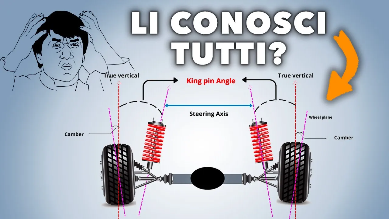
The angle at which the control arms attach determine things like toe angle and caster angle, which could be a whole separate video in itself. So, I'll spare you from the explanation here until another time. But one thing I do want to talk about is how I design complex kinematics like these suspension arms and the geometry of the steering rack.
It seems like a daunting thing to design and you never really know where to start. So what I like to do is just start in the simplest possible form with just lines sketched out representing each of the bars in the four bar linkage. Here I'm looking at how the relationship between the length of the upper and lower control arms results in changing camber in the wheel along the full range of motion. If you were to design a full 3D part in order to go back and change the geometry slightly, you'd have to redesign that whole part.
This allows you to play with the mechanical systems and really quickly tune the geometry before locking in critical dimensions. I tested one such idea early on in the design process when I was considering doing push rod suspension to lower the total height of the chassis, but through mocking it up with just simple lines in Solid Works, I was able to rule it out fairly quickly as a viable solution in this particular case. Before installing them onto the chassis, I added some 30K diff fluid to tune the amount of resistance each of the diffs have. And I should note that within the diff casing, I'm using white lithium grease this time so that all you folks watching don't skewer me in the comments for lack of lube. Again, I kind of felt like I was P. Diddy, only I was getting cancelled for a lack of baby oil. The suspension towers here are a separate part because I wanted to be able to tune and test a bunch of different geometries as I searched for the right set of shocks. I sourced a waterproof 25 kg servo which has more than enough oomph to steer the car at speed, but is compact enough to fit between the edge of the chassis and the drive shaft. The steering rack design is simple. It's another four bar linkage where the arms pivot around these posts that are integrated into the chassis plate and are secured with a couple M3 screws on top. I'm pretty dumb, but I learned from mistakes, so I'm using off-the-shelf bearings for this drive pinion instead of 3D printed ones. Then to clamp the top half of the casing to the bottom half of the diff casing, I use these 30mm M3s. To connect the 3D printed drive shaft to the hardened steel drive pinion and the front differential, I used a threaded insert that allows a set screw to be tightened against that pin. The opposite end of that drive shaft has that cross feature that interfaces with the cups on the center diff. And once that's slid into place, it can be locked in that position by tightening down the screws on the bottom of the chassis plate that have slotted holes and allow for some micro adjustment. At the rear of the chassis, the drive shaft is much shorter, but it uses the exact same mechanical design as the longer shaft. Once the rear diff is slid into place and tightened down, the drivetrain is more or less complete. You can see that the whole chassis plate has flex to it, and that flex creates an opening and closing gap between the shaft and the diff casing. To fix this issue and to just generally stiffen up the whole chassis, I use this structural beam to tie together the top of the front and rear diff. It has little alignment pin features that help guide it into position. And once this is torqued down, it's pretty remarkable how stiff the chassis feels. When I really give it my best effort to flex it, I can't even get that gap to open up. So, the drive shaft stays perfectly aligned.
All eight control arms are attached with these 3mm e-clipip pins, 50 mm and 25 mm in length. In this case, there's just really no substituting with a 3D printed part. You need the strength of a steel pin. And you'll see exactly why that is in a moment. And if we were to use a screw and a nut, it would slowly come undone over time. So, as far as I can tell, these are the best possible solution. The knuckles have a bunch of small finicky bits, but the build guide has really detailed and clear instructions that show you the exact stack up and assembly. And for the off-the-shelf parts, like the 55mm axle and the E-clip, there are links embedded into the guide to help you order them.
The front knuckles are just like the rear knuckles, except there's an extra axis of freedom that allows the wheels to rotate while steering. So, there's a few additional parts in this assembly.
The servo is liquidy smooth, and the drive shafts are sending power to both diffs. So, I'm ready to put on the first pair of shocks that I tried out. And after mounting the wheels and tires, I was ready to take it out for its first test drive. I need to pause quickly here and humbly request that if you like this channel, please like and subscribe.
You're not going to want to miss getting alerted for the next video where we're going to take you through a full industrial design process of designing and building a car from scratch. Please help us to not have to get real jobs.
Okay, back to the video. And shout out to the true fans who know why that front right tire is purple. The first thing I noticed is that the springs weren't quite stiff enough, so when I cornered hard, I could hear the chassis plate scraping on the ground. And the rebound was a bit too sluggish, so I was losing traction really easily.
I did about 15 minutes of back and forth laps running the chassis through all the paces and trying to observe what was happening to the suspension while cornering, braking, and accelerating.
Now, granted, mounting my iPhone to the top gave it a really high center of gravity and made the handling much worse, but still, it was clear that the suspension needed some recalibration.
Now, I like to practice a type of engineering called crash it and then fix what broke when it crashed. So, at the end of the session, I decided to run it into one of the logs and see what broke first.
Now, you'll recall I mentioned we really needed to have metal e-clipip pins here instead of 3D printed ones. And this is the main reason why. Anytime there's any sort of collision with this chassis, it's going to send a lot of that force straight into that pivot point at the lower control arm. But here's where a 3D printable RC car starts to really outshine a retail one. Once you have the files, you can just reprint as many times as you crash it. And the chassis is designed to be extremely modular. So, it's only like a 10-minute fix to swap out the control arm. Since the control arm was the part that failed in the crash, I changed the print settings to be three wall loops and 85% infill instead of 15. And this thing is so much more solid now. I made a number of other design edits as well, like redesigning the motor mount to be slightly stiffer.
So, instead of using that cleat, having a third attachment point with a screw.
Also, I felt like the gear ratio was a little bit short, and nothing exploded when I ran it into that log, which means we're definitely not going fast enough.
So, I decided to up the drive pinion from 12 to 15 to here, I'm tightening down that third screw on the new motor mount. Final update was redesigning the suspension to be a little bit more calibrated to the weight of this chassis. The shocks I used were a little bit too soft in terms of spring stiffness, and you could see it, especially when braking and cornering, how the front end would dive and be very sluggish to rebound. So, given that I designed this part to be modular, I just had to change the geometry slightly, reprint, and then source a new set of shocks with the right specs.
The old drop test proved that these shocks were a much better match.
Immediately, I could tell I like the ratio better with the new 15- drive pinion. I set up this side view camera mount to try and get a better picture of what the drive shafts were doing, but it ended up just being a really cool shot of the rear suspension at work. I took it out to some dirt trails to really test the new suspension, and it's crazy how much better this thing handles with a properly calibrated set of shots.
Again, the high center of gravity of my iPhone mounted to the top was throwing off the handling a bit, so I was constantly swapping back and forth with the camera mount.
Onroads, the thing is so buttery smooth and so fast with the new ratio. I felt like an F1 pilot, and I was actually a little worried about killing my iPhone if I crashed. So, I was trying to drive very conservatively when I had my phone mounted to it.
You can see the front end dive characteristics are a lot friendlier with this version. When I slam on the brakes or corner, it rebounds nice and smoothly. Another reason I opted for off-the-shelf links here is so that you can dial in the toe of the front end in real time to get perfect handling. So, if you want to drive one of these things, you should go over to my website, curvlab.com, and download the files. And the best part is it's kind of like you have a lifetime subscription to this chassis because if you crash it, you can just reprint and replace that part. And we have a super exciting new project being released very soon on this channel. So if you want to stay up to date, please hit the like and subscribe button and stay tuned for the next video where we're going to take you through a full industrial design process of designing and building a car from scratch. Thanks for watching. Until next time.
Up Next

How NASA's Perseverance Rover Works: Mars Exploration Explained
@JaredOwen
4.8M views•2022-07-01

Ultrasonic Transducers: Resonant Frequency Measurement and Horn Design
@imajeenyus42
229.9K views•2017-02-22

Polymer Environmental Degradation: Mechanisms & Stabilization
@iit
1.8K views•2012-07-10

How a Student's Question Saved a NYC Skyscraper from Collapse
@veritasium
22.8M views•2025-04-26
Related Study Plans & Knowledge Roadmaps
Structured learning paths in Engineering