A seismic air gun operates by using high-pressure air (2000-2500 psi) stored in two chambers—a control chamber and a discharge chamber—that forces air through a shuttle valve into surrounding water, creating bubbles that oscillate and generate acoustic waves for subsurface imaging; the rapid opening of the solenoid valve (milliseconds) enables quick air discharge, and the shuttle resets automatically when the discharge chamber refills.
Marine Seismic Survey Airgun Operation Explained
Added:Deep Dive
Fundamentals of acoustic wave propagation and behavior in fluid mediums (water).
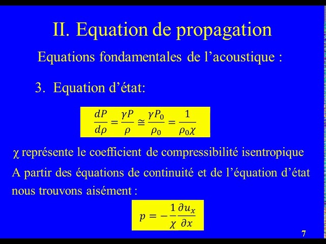
Onde acoustique résumé de cours Partie 1
2.8K
Acoustic waves are mechanical pressure waves that propagate through fluid media (air, water) at approximately 340 m/s under standard conditions, characterized by small pressure variations (1-100 Pa) relative to equilibrium pressure (~10^5 Pa), enabling linear acoustic approximation; their propagation follows the wave equation derived from Newton's second law, mass conservation, and state relations, with key parameters including acoustic impedance (Z = ρ₀c), kinetic energy density (½ρ₀|u̇|²), potential energy density (½p̄²/ρ₀c²), and intensity (I = ½|p̄|²/Z), while reflection and transmission at medium boundaries depend on impedance matching.
Click to watch →

Acoustics
740
Acoustic wave theory assumes inviscid fluids where particles only move longitudinally without shear deformation. Waves exhibit periodicity in space (wavelength λ) and time (period T), governed by c = f × λ where c is speed of sound. In air, c ≈ 340 m/s; in water, c ≈ 1400 m/s. Human hearing spans 16 Hz to 16 kHz with thresholds from 20 μPa (hearing) to 200 Pa (pain). Loudness perception follows logarithmic scales, motivating the decibel scale for measuring sound pressure levels.
Click to watch →

Underwater Acoustics
28K
Sound travels through water as longitudinal waves with oscillating water molecules exchanging energy. Unlike radio or light, sound propagates effectively over kilometers underwater. Sound is analyzed using ray paths connecting sources to receivers. Refraction occurs when sound crosses boundaries between regions of different sound speeds, always bending toward lower sound speed values. A sound channel forms where sound speed reaches minimum depth, trapping sound in horizontal propagation. Understanding these principles is essential for predicting how sound will travel between any underwater source and receiver.
Click to watch →

ACÚSTICA | AULA 01 | QUALIDADES FISIOLÓGICAS DO SOM
51.4K
Sound is a mechanical longitudinal wave requiring a material medium (solid, liquid, or gas) to propagate, unlike electromagnetic waves that travel through vacuum. In fluids, sound waves consist of alternating compressions and rarefactions where particles vibrate parallel to wave propagation. The speed of sound varies significantly with medium: approximately 5000 m/s in iron, 1500 m/s in water, and 340 m/s in air. This variation occurs because molecular spacing and bonding strength differ between media, affecting how quickly vibrational energy transfers.
Click to watch →

Résumé de cours ondes acoustiques dans les fluides partie 2
11.1K
This video explains the fundamental principles of acoustic wave propagation in fluids, including the derivation of D'Alembert's equation for pressure waves, the relationship between wave speed, mass density, and compressibility coefficient (v = √(γRT/M) for ideal gases), the concept of acoustic impedance (Z = ρv), and the calculation of sound energy (kinetic plus potential) and intensity (I = p²/(ρv)). It also covers the logarithmic decibel scale for measuring sound levels (L = 10 log₁₀(I/I₀)) and the reflection/transmission phenomena at medium boundaries governed by continuity of pressure and particle velocity.
Click to watch →
Deep Dive
Basic principles of thermodynamics, specifically pressure-volume relationships and gas expansion laws.
![[Vật Lí 12 - SGK Mới] Chữa 1000 Câu Lí Thuyết Xác Suất Cao - Buổi 3 - 50 Câu | Thầy VNA](https://i.ytimg.com/vi/Q_Dn5WvjxHc/maxresdefault.jpg)
[Vật Lí 12 - SGK Mới] Chữa 1000 Câu Lí Thuyết Xác Suất Cao - Buổi 3 - 50 Câu | Thầy VNA
13.3K
This section covers gas laws and thermodynamic principles: (1) Gas law application for balloon volume calculation; (2) Isothermal compression - pressure-volume relationship (P1V1 = P2V2); (3) Isobaric process identification in PV diagrams; (4) Multi-step thermodynamic process temperature calculation; (5) Bubble expansion - pressure-volume relationship; (6) Gas expansion - pressure-volume relationship; (7) Air leakage - density and temperature relationship; (8) Temperature and kinetic energy relationship; (9) Temperature and volume relationship in PV diagrams; (10) Charles's Law - volume proportional to absolute temperature at constant pressure; (11) Temperature and pressure relationship in isochoric processes (P ∝ T); (12) PV diagram analysis - temperature proportional to PV product; (13) Gas law application for balloon volume calculation; (14) Isothermal compression - pressure-volume relationship (P1V1 = P2V2); (15) Isobaric process identification in PV diagrams; (16) Multi-step thermodynamic process temperature calculation; (17) Bubble expansion - pressure-volume relationship; (18) Gas expansion - pressure-volume relationship; (19) Air leakage - density and temperature relationship; (20) Temperature and kinetic energy relationship; (21) Temperature and volume relationship in PV diagrams.
Click to watch →

general laws for expansion and compersion | thermodynamics Basic concept
255
The general laws for gas expansion and compression describe the relationship between pressure and volume of a gas, which depends on the nature of the gas and the conditions under which the process occurs, such as isothermal (constant temperature) or adiabatic (no heat exchange) conditions.
Click to watch →

AP Physics 2 - Unit 2 Notes Thermodynamics
325
When thermal energy is added to solids and liquids, their dimensions change according to ΔL = αL₀ΔT (linear expansion) and ΔV = βV₀ΔT (volume expansion), where α and β are material-specific coefficients. For gases, three fundamental laws describe behavior: Boyle's Law (P ∝ 1/V at constant T), Charles's Law (V ∝ T at constant P), and Gay-Lussac's Law (P ∝ T at constant V). The ideal gas law combines these as PV = nRT or PV = NkT, relating pressure, volume, temperature, and amount of gas.
Click to watch →

Thermodynamics part -7
389
The video explains the inverse relationship between pressure and volume during gas expansion. When pressure is applied to a gas, the volume decreases (compression), and when pressure is reduced, the volume increases (expansion). The instructor demonstrates this using a piston-cylinder setup where the gas volume changes from an initial minimum value to a final maximum value. The work done by the gas during expansion is positive, while work done on the gas during compression is negative. This relationship is fundamental to understanding thermodynamic processes and the behavior of gases under different pressure conditions.
Click to watch →
حل اختبارات الاسترشاديه (الصف الثاني الثانوي)
276
Gas laws describe how pressure, volume, and temperature relate for gases. Boyle's Law states pressure and volume are inversely proportional at constant temperature (P₁V₁ = P₂V₂). Charles's Law states volume and temperature are directly proportional at constant pressure (V₁/T₁ = V₂/T₂). The Combined Gas Law combines these relationships. For example, a gas at 1 atm and 25°C (298 K) with 25 cm³ volume heated to 102°C (375 K) at constant pressure expands to approximately 31.3 cm³.
Click to watch →
Deep Dive
An introduction to reflection seismology and how sound waves are used to image sub-surface geological structures.

October Public Lecture - From catastrophism back to uniformitarianism
760
Seismic reflection profiling uses powerful sound waves emitted from a source towed behind a ship to image subsurface geological structures. The sound waves penetrate through sedimentary layers and bounce off boundaries between different materials (such as between sediments and bedrock). These echoes are detected by hydrophones towed behind the ship, allowing geologists to create detailed cross-sectional images of the ocean floor and underlying geological structures, revealing sediment thicknesses of over two kilometers representing vast spans of geological time.
Click to watch →

How Faults Move Deep Underground: The Origin of Earthquakes
7.2K
Reflection seismology is the primary technology available to image the first five to ten kilometers of the subsurface with good detail. This method works by sending seismic waves into the ground and recording how they reflect off different rock layers and structures. Geologists then interpret these seismic cross-sections to reconstruct subsurface geological features including faults, folds, and stratigraphic layers.
Click to watch →

Science Breaks: Exploring volcanoes, old and young
1.2K
Reflection seismology is a technique for imaging the Earth's subsurface, essentially taking an X-ray of the Earth. It works by using a boat with an acoustic energy source (like a giant bubble) that sends sound waves into the ground. These waves bounce off different rock layers and are detected by hydrophones trailing behind the boat, creating 3D images of the subsurface based on rock density and sound wave speed.
Click to watch →

Seismic Reflection Principles in Geophysical Interpretation
39.8K
Seismic reflection is a geophysical technique that images subsurface geological structures by sending acoustic pulses into the Earth and recording the reflected waves; the reflection occurs at interfaces where acoustic impedance (product of rock velocity and density) changes, with the reflection coefficient determining the amplitude of the returned signal, and seismic resolution typically resolves units of 20-30 meters thickness, enabling identification of depositional sequences and sequence boundaries while distinguishing between different rock types and fluid contents.
Click to watch →
Mysterious Underground Anomalies on The Curse of Oak Island Explained!
7.1K
Reflection seismology is a geophysical method that sends seismic waves into the ground and detects the reflections that bounce back from subsurface interfaces. These interfaces are created by changes in rock density and velocity. The method creates images of the subsurface similar to medical ultrasound, though with lower resolution. The depth is measured in travel time rather than actual depth because seismic wave velocity varies throughout the earth.
Click to watch →
Deep Dive
Elementary mechanical engineering concepts, particularly the operation of valves, chambers, and pressure seals.

Types of Valves Explained in Tamil | Mechanical Engineering Basics 🔧
1.3K
This video explains the five main types of valves used in mechanical engineering: (1) Gate Valve - used to open or close flow, commonly found in domestic water tanks and industrial pipelines; (2) Globe Valve - used for pressure control, allowing gradual adjustment of fluid flow; (3) Check Valve (Non-Return Valve) - allows flow in one direction only and prevents backflow, used in air compressors, gas cylinders, and bicycle tires; (4) Pressure Relief Valve (PRV) - automatically releases pressure when it exceeds safe limits and closes when pressure returns to normal, commonly found in pressure cookers; (5) Safety Valve - releases all pressure when critical thresholds are reached and cannot be manually closed, serving as a critical safety device in pressurized systems.
Click to watch →

इंजन के मुख्य भाग एवं उनकें नाम (Main parts of engine and their name)#automobile #dieselengine #car
805.3K
Valve springs and locks control valve operation by providing closing force and securing components. The valve train includes camshaft, pushrods, rocker arms, and valve springs working together. Gaskets seal mating surfaces between components like cylinder head and block. The entire valve train must operate precisely to maintain proper valve timing. Proper sealing prevents gas and fluid leakage, maintaining engine efficiency and preventing damage.
Click to watch →
Basic Mechanical Interview Questions Answers For Mechanical Diploma holder.
47.9K
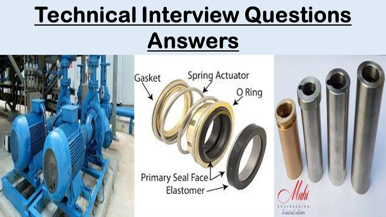
This section covers essential mechanical engineering concepts including: (1) Mechanical seal function in centrifugal pumps to prevent liquid leakage, consisting of rotating and stationary components; (2) Three main causes of mechanical seal failure: dry running, vibration, and improper bearing placement; (3) Primary (face seal) and secondary (O-ring) seal types; (4) Welding as a metal joining method without melting; (5) Bolt length measurement from center-to-center of pin holes; (6) Hydraulic pump function converting mechanical energy to hydraulic energy; (7) Gate valves for steam lines; (8) Positive displacement pumps for high-pressure applications; (9) Screw pump characteristics with smooth, quiet operation; (10) Pump applications for liquid transfer in industries; (11) Single-stage vs multi-stage pumps for water applications.
Click to watch →
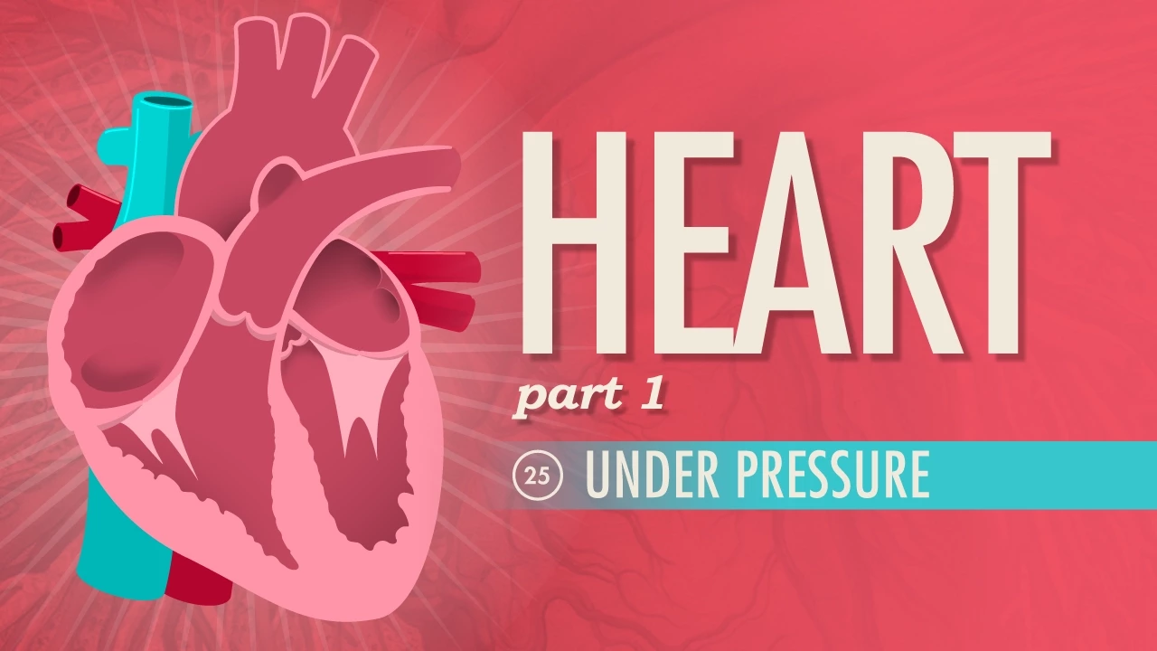
The Heart, Part 1 - Under Pressure: Crash Course Anatomy & Physiology #25
7.6M
The heart uses valves to ensure unidirectional blood flow: atrioventricular valves (mitral/tricuspid) prevent backflow between atria and ventricles, while semilunar valves (aortic/pulmonary) prevent backflow from arteries. The pulmonary circulation loop carries deoxygenated blood from right ventricle to lungs via pulmonary arteries, where gas exchange occurs in capillaries. Oxygenated blood returns via pulmonary veins to left atrium. The systemic circulation loop then distributes oxygenated blood from left ventricle through aorta to body tissues, returning deoxygenated blood via vena cava to right atrium. This double-loop system ensures continuous oxygen delivery to cells.
Click to watch →

Dissecting an Engine, The Basic Parts and Their Functions - EricTheCarGuy
4.2M
Valves seal against valve seats in the cylinder head, with valve jobs resurfacing seats at multiple angles for proper sealing. Valve springs push valves closed after camshaft opening, with spring strength determining high-RPM capability—weak springs cause valve float where valves stay open too long. Positive type valve seals prevent oil from entering combustion chambers, unlike umbrella-style seals. Valve guides allow valve movement while maintaining alignment, with wear causing oil consumption problems.
Click to watch →
Prerequisite Knowledge
- Concept 01Fundamentals of acoustic wave propagation and behavior in fluid mediums (water).
- Concept 02Basic principles of thermodynamics, specifically pressure-volume relationships and gas expansion laws.
- Concept 03An introduction to reflection seismology and how sound waves are used to image sub-surface geological structures.
- Concept 04Elementary mechanical engineering concepts, particularly the operation of valves, chambers, and pressure seals.
Subsequent Learning
- Step 01Acoustic monitoring and the design of hydrophone arrays (streamers) to capture reflected seismic signals.
- Step 02Seismic data processing techniques, including filtering noise and converting acoustic travel-time into depth profiles.
- Step 03The environmental and ecological impacts of marine seismic surveys on marine life, and current mitigation technologies.
- Step 04Alternative marine seismic source technologies, such as marine gas-exploders or marine vibrators (vibroseis).
Airgun Mechanics
Airgun Mechanics
0:00Playing Section
- 1
Two-chamber airgun design controls high-pressure air discharge.
- 2
Electrical pulse triggers rapid shuttle movement for bubble generation.
- 3
Bubble oscillation depends on pressure, depth, temperature, and volume.
Marine Vibroseis and Environmental Mitigation of Acoustic Pollution
While traditional marine seismic surveys rely on impulsive, high-pressure airguns to image the sub-surface, this method is heavily criticized for its severe ecological impacts. Environmental scientists and marine biologists point out that the intense, low-frequency sound pulses can disrupt marine mammal communication, cause temporary or permanent hearing loss, and harm fisheries and zooplankton populations. In response, an alternative technological perspective champions "Marine Vibroseis" (marine seismic vibrators). Unlike airguns, which release sudden, explosive bursts of energy, Marine Vibroseis systems emit continuous, lower-amplitude, frequency-modulated signals over a longer duration. Proponents of this alternative argue that transitioning to vibratory sources significantly mitigates acoustic pollution and minimizes harm to marine ecosystems while still capturing high-quality geophysical data. This counterpoint emphasizes that the future of marine geophysics must prioritize ecological safety through the abandonment of high-peak-pressure impulsive sources in favor of gentler, continuous-wave alternatives.
Deep Dive
Acoustic monitoring and the design of hydrophone arrays (streamers) to capture reflected seismic signals.
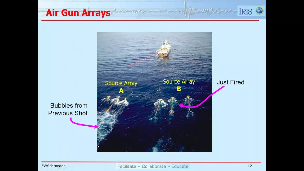
Seismic Acquisition: Land & Marine Methods Explained
33.9K
Marine receivers called hydrophones detect pressure waves in water. They consist of metal outer casings with pressure sensors inside, featuring holes allowing water pressure sensing. These devices are housed in flexible silicon-filled tubes called streamers, which are neutrally buoyant and trail behind the acquisition vessel. Modern streamers are typically 5-7 kilometers long, containing multiple hydrophones spaced along their length to capture seismic reflections from various depths.
Click to watch →

Array October Session Two: OOI Regional Cabled Array, Overview and Acoustic Applications
211
The RCA deploys six broadband hydrophones (Ocean Sonics iCListen HF) sampling at 64 kilosamples per second with 24-bit conversion, planned to increase to 256 kilosamples per second for measuring signals up to 120 kHz. Four broadband hydrophones operate on the seafloor at depths ranging from 80 to 2900 meters, while two operate in the water column at 200 meters depth. Five low-frequency hydrophones (HDI 90) are coupled with broadband seismometers, sampled at 1 kilosample per second, primarily to remove waterborne signals from seismic recordings. These hydrophones detect waterborne acoustic events associated with seismic activity, including magma flow onto the seafloor, gas bubble explosions, pillow lava imploding, and other hydrothermal processes. During the 2015 Axial Seamount eruption, hydrophones detected synchronous events with short-period seismometers, revealing lava cooling by water and gas release processes that complement traditional seismic recordings.
Click to watch →

GEOP3041-General Geophysics-reflection 3
542
Marine seismic streamers contain multiple hydrophones arranged in groups, typically containing 12, 24, or more individual hydrophones depending on desired data quality. Multiple hydrophones are connected together to form a single trace, which increases the signal-to-noise ratio of the recorded data. The number of hydrophones per group and the spacing between groups directly impacts data resolution and quality. Higher-quality data acquisition requires more hydrophones per group and closer spacing between groups, though this also increases operational complexity and cost.
Click to watch →

Underwater sound and the BC Coastwide Hydrophone network
171
Acoustic monitoring systems include shore-based components with solar panels and batteries, foldable tripods for seafloor deployment, and armored cables for intertidal protection. Systems can be designed as on-grid or off-grid with multiple computers for data logging. Small boat deployable buoys allow boats to move away from noise sources. Current development projects include improved low frequency hydrophone calibration systems, collapsible moorings, and array-capable buoys for direction finding. These developments aim to improve field deployment and monitoring capabilities for marine acoustic research.
Click to watch →

Scripps Technical Forum: GeoSpectrum Technologies Inc
460
Acceleration-canceling hydrophones use symmetrical dual-ceramic construction with parallel wiring—compression in one ceramic cancels tension in the other when force acts on the central mount, eliminating acceleration-induced noise. Proper mounting is critical; force on the bottom prevents cancellation. These hydrophones are essential for seismic surveys and vertical arrays where dynamic forces couple through the hydrophone. In towed arrays, thousands of newtons of fluctuating force in the strength member overwhelm acoustic signals at the piconewton level. Decoupling hydrophones inside cages that carry all forces allows them to hang freely without mechanical coupling. Hydrophone design involves fundamental trade-offs: increasing voltage sensitivity requires larger diameter, lowering resonance and increasing diffraction. Increasing capacitance requires thinner walls, sacrificing depth capability. Higher capacitance reduces low-frequency noise but may sacrifice high-frequency performance. The energy harvesting relationship (½CV²) shows doubling all dimensions increases active material by eight times, doubling voltage and capacitance while halving resonance, demonstrating inherent competition between high-frequency and low-frequency performance.
Click to watch →
Deep Dive
Seismic data processing techniques, including filtering noise and converting acoustic travel-time into depth profiles.
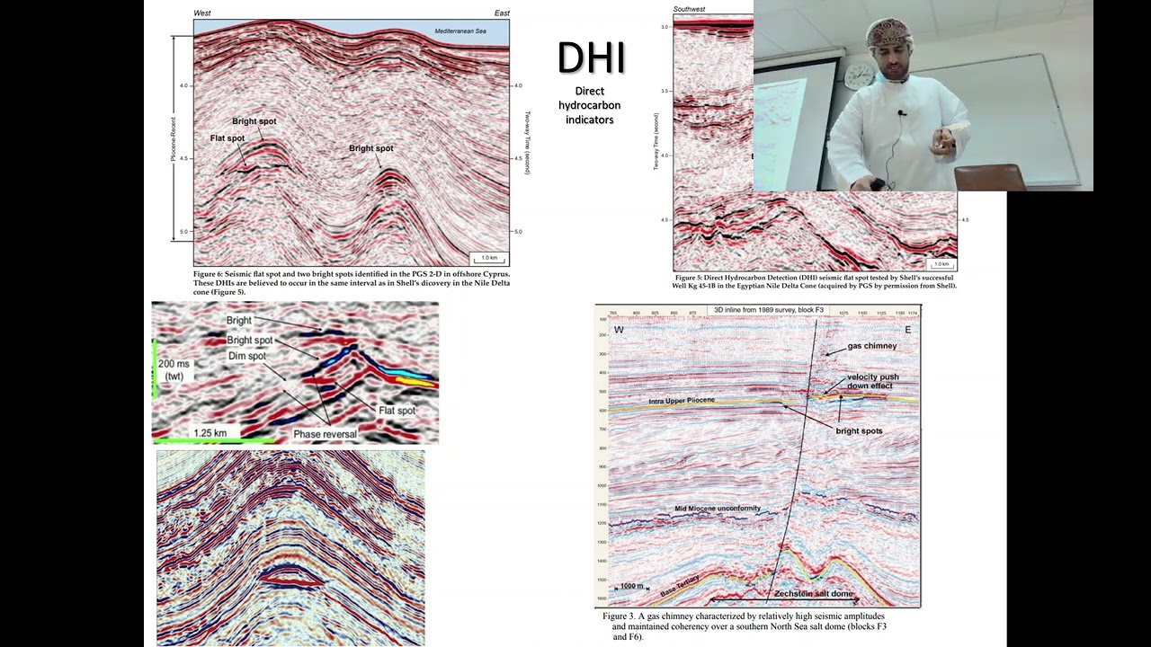
GEOP3041-General Geophysics-Gravity method 1
1.1K
Depth conversion is the process of converting seismic data from time domain to depth domain. This requires velocity information about the subsurface rocks. Common methods to obtain velocity data include Common Depth Point (CDP) analysis and Common Midpoint (CMP) analysis. Depth conversion allows geologists to interpret subsurface structures at actual geological depths rather than two-way travel times.
Click to watch →
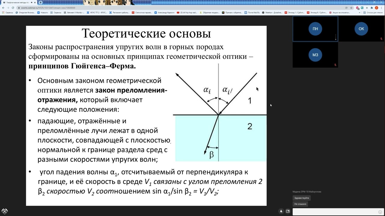
Геофизические методы поисков и разведки месторождений полезных ископаемых
360
Seismic data acquisition involves sources, receivers, cables, and stations. Raw data contains multiple wave types: direct waves (straight lines), reflected waves (hyperbolas), refracted waves (offset straight lines), and surface waves. Environmental vibrations from trees and machinery add noise. Processing separates useful signals from noise using filters and characteristic wave patterns. Modern software enables rapid processing with mouse clicks, replacing manual hand-drawn analysis. Time records are converted to depth records using known velocities, transforming temporal sections into geological cross-sections for interpretation.
Click to watch →

Tercera clase Manejo y Aplicación de software libre en sismología 2020 08 01.
493
Seismic data can be filtered by depth using the 'awk' command with conditional statements. The command checks specific columns in the data file (e.g., column 5 for depth) and extracts data meeting certain criteria (e.g., depth ≤ 60 km for shallow earthquakes). This creates separate data files for different earthquake depth categories.
Click to watch →

الطريقة السيزمية( الزلزالية)Seismic Methodوالمسح الجيوفيزيائي بالطريقة السيزمية للاستكشاف الجيولوجي
2.6K
Seismic data processing involves: (1) Data acquisition - recording raw seismic signals; (2) Pre-processing - filtering, noise reduction, and signal enhancement; (3) Migration - correcting for wave propagation effects; (4) Interpretation - identifying geological structures. Noise sources include equipment noise, environmental noise (wind, traffic), and natural seismic noise. Noise reduction techniques include stacking multiple traces, filtering, and using directional geophones. High-quality seismic data requires careful noise management throughout the survey process.
Click to watch →
AULA 15 -TRAÇO SÍSMICO
767
The main objectives of seismic data processing include: (1) Removing the effects of the input signal to isolate the reflectivity series, (2) Determining velocity functions to convert time axes to depth axes, (3) Determining acoustic impedances of different layers to understand subsurface properties. These processing steps are essential for obtaining interpretable seismic data that reveals subsurface geological structures.
Click to watch →
Deep Dive
The environmental and ecological impacts of marine seismic surveys on marine life, and current mitigation technologies.

Seismic experiences undertaking 2D & 3D surveys in Algoa and St Francis Bay - Jean Malan
232
Marine seismic surveys implement comprehensive environmental protection measures including: (1) 500-meter mitigation zones monitored by marine mammal observers, (2) Passive acoustic monitoring during nighttime and poor visibility, (3) Seabird observers from academic institutions, (4) Fishery liaison officers for local industry coordination, (5) Chase boats maintaining safety perimeters. Marine life actively avoids survey areas, with dolphins, seals, and penguins relocating outside the mitigation zone. Research spanning over 50 years by the US Bureau of Energy Management found no documented evidence of adverse effects on marine mammal populations or coastal communities. Once surveys conclude, marine life returns to normal patterns within days to weeks.
Click to watch →
Sperm Whales - Titans of the Deep | Free Documentary Nature
3.8M
Since the late 1980s, marine scientists observed sharp increases in sperm whale strandings coinciding with intensified oil and gas exploration using seismic surveys. These operations use huge pressure cannons that produce air bubbles collapsing to send pressure waves shaking the ocean floor thousands of meters deep. Sound travels through sound channels between water layers of the same temperature, radiating sideways for thousands of kilometers. Marine biologists observed that strandings always occurred during winter migration when bulls returned to their Azorean clans. Laboratory analyses showed whales appeared healthy, yet they abandoned traditional routes toward shallow North Sea waters at depths of only 200 meters, suggesting acoustic disturbance as a primary driver of this behavioral shift.
Click to watch →
Oceans - The EEZ Act and the protection of marine mammals - Simon Childerhouse
116
Seismic surveys impact marine mammals through three documented categories: (1) Physical/physiological effects including temporary and permanent threshold shifts in hearing, and potential decompression sickness from rapid surfacing; (2) Behavioral disruption including avoidance of noise areas, changes in vocalization patterns, and altered movement; (3) Indirect effects such as prey displacement that may break up krill or plankton balls, making feeding more challenging. The impacts can occur over tens or hundreds of kilometers. However, responses are highly variable by species, time of year, water depth, and latitude, making it difficult to establish hard-and-fast rules for mitigation.
Click to watch →
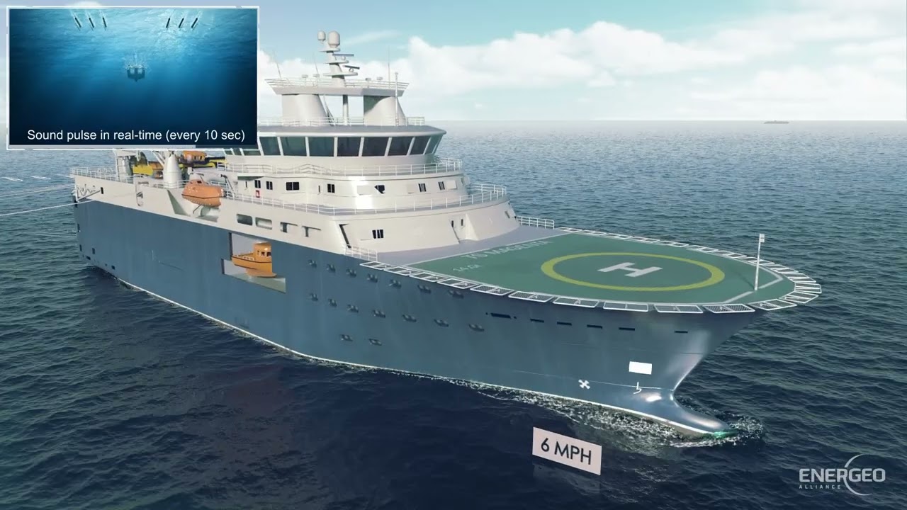
Seismic Surveys in Context 2025
523
Seismic surveys produce sound only approximately 1% of the time (about 1/10th second pulses every 10 seconds), with operations stopped 20-30% of the time for maintenance, weather, and mitigation measures; the actual surveyed area is extremely small compared to permitted zones, and marine mammals are sparsely distributed and often avoid the sound source, resulting in minimal environmental impact on marine life.
Click to watch →
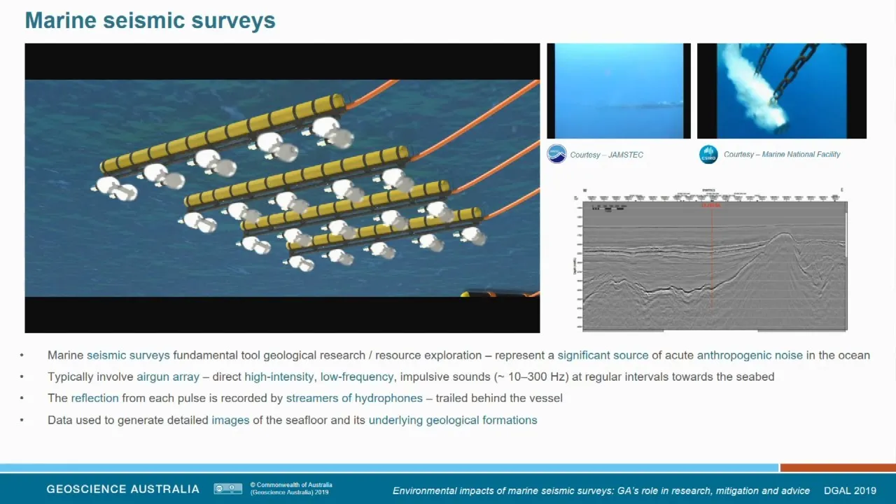
Environmental Impacts of Marine Seismic Surveys
3.6K
Marine seismic surveys, which use airgun arrays to map geological structures beneath the ocean floor, generate significant low-frequency acoustic noise that can potentially impact marine life, including physical effects (hearing damage), behavioral changes, and indirect effects on food sources; however, comprehensive research by Geoscience Australia demonstrates that impacts are highly context-dependent and vary significantly across species, with no universal negative effects observed in all cases, emphasizing the need for site-specific monitoring and integrated scientific approaches to balance resource exploration with environmental protection.
Click to watch →
Deep Dive
Alternative marine seismic source technologies, such as marine gas-exploders or marine vibrators (vibroseis).

Vibroseis - Part 1
3.5K
Vibroseis is a seismic source technology developed in the 1950s that provides a safer and environmentally friendly alternative to explosive sources by using vibrating sources that impart moderate energy over longer time periods, achieving comparable signal-to-noise ratios through multiple sources and signal stacking, while avoiding the costs, regulations, and safety concerns associated with explosive sources.
Click to watch →

EAGE Seismic Acquisition: Marine Seismic Source Technology
2.2K
This comprehensive section traces the evolution of marine seismic source technologies from early water guns through modern innovations. It covers conventional air gun arrays with their bubble dynamics, the Gigan source achieving 20% primary-to-bubble ratios, and the Blueprint source mitigating high-frequency footprints. The presentation then transitions to the e-seismic continuous wave field method, which distributes small air guns continuously rather than firing simultaneously, enabling better source-side sampling and reduced environmental impact. Marine vibrators are introduced as the controlled-source alternative, transmitting energy over 10-30 second periods instead of releasing 99% of energy in the first 30 milliseconds as impulsive air guns do. This fundamental difference enables significantly lower environmental impact while maintaining comparable subsurface illumination. The section concludes with the JIP vibrator system (2,500 kg units, 36 per survey) and Aqua Vib (shallow water deployment), demonstrating practical implementations achieving 20+ dB lower peak amplitudes than conventional air guns.
Click to watch →

Lecture 2: Seismic Principles 2
6.4K
Vibroseis (Vibroseis®) is a patented vibratory source that is highly repeatable, linear, and inexpensive for large-scale surveys. It provides frequency control from 10-200 Hz and can image reflectors through the entire crust. However, trucks cost about $500,000 each, and mobilization costs $80,000 per truck. Mini Vibroseis (Mini Sosie) uses pavement whackers as low-cost vibratory sources, though only one crew remains in the US. Marine vibrators and borehole vibrators can operate at kilohertz frequencies.
Click to watch →

Procesos en la industria del petróleo y gas
1.5M
Marine seismic surveys use scientific vessels towing cables carrying geophones and air guns. The air guns expel high-pressure compressed air, generating waves that travel through the seabed and subsurface formations. These waves bounce back to be identified by geophones and analyzed by geologists to map underwater geological structures.
Click to watch →

Offshore Gas: The Whale in the Room for Australian Governments - webinar recording
577
Research conducted in late 2021 tested alternative seismic source technologies designed to reduce impacts on marine life. Animals exposed to these alternative sources showed significantly better responses compared to conventional air guns, with animals appearing 'a lot more happy.' This suggests that technological modifications to seismic sources may offer a pathway to reducing environmental impacts while still enabling necessary geological exploration for hydrocarbon resources.
Click to watch →
Airgun Mechanics
Airgun Mechanics
0:00- 1
Two-chamber airgun design controls high-pressure air discharge.
- 2
Electrical pulse triggers rapid shuttle movement for bubble generation.
- 3
Bubble oscillation depends on pressure, depth, temperature, and volume.
Marine Vibroseis and Environmental Mitigation of Acoustic Pollution
While traditional marine seismic surveys rely on impulsive, high-pressure airguns to image the sub-surface, this method is heavily criticized for its severe ecological impacts. Environmental scientists and marine biologists point out that the intense, low-frequency sound pulses can disrupt marine mammal communication, cause temporary or permanent hearing loss, and harm fisheries and zooplankton populations. In response, an alternative technological perspective champions "Marine Vibroseis" (marine seismic vibrators). Unlike airguns, which release sudden, explosive bursts of energy, Marine Vibroseis systems emit continuous, lower-amplitude, frequency-modulated signals over a longer duration. Proponents of this alternative argue that transitioning to vibratory sources significantly mitigates acoustic pollution and minimizes harm to marine ecosystems while still capturing high-quality geophysical data. This counterpoint emphasizes that the future of marine geophysics must prioritize ecological safety through the abandonment of high-peak-pressure impulsive sources in favor of gentler, continuous-wave alternatives.
Fundamentals of acoustic wave propagation and behavior in fluid mediums (water).
Basic principles of thermodynamics, specifically pressure-volume relationships and gas expansion laws.
An introduction to reflection seismology and how sound waves are used to image sub-surface geological structures.
Elementary mechanical engineering concepts, particularly the operation of valves, chambers, and pressure seals.
Acoustic monitoring and the design of hydrophone arrays (streamers) to capture reflected seismic signals.
Seismic data processing techniques, including filtering noise and converting acoustic travel-time into depth profiles.
The environmental and ecological impacts of marine seismic surveys on marine life, and current mitigation technologies.
Alternative marine seismic source technologies, such as marine gas-exploders or marine vibrators (vibroseis).
8.8K views51likes1:20@Geousman101.Original Release: 2021-06-15
[Music] a modern airgun seismic source element comprises of two high pressure air chambers an upper control chamber and a discharge chamber high pressure air typically at two thousand to two thousand five hundred pounds per square inch or psi is supplied to the upper control chamber from the compressor on board the seismic vessel via an air hose and slowly moves into the lower discharge chamber through an opening in the shuttle assembly the source is activated by sending an electrical pulse to the solenoid valve which opens allowing high pressure air to flow to the underside of the piston the high pressure air in the lower chamber is discharged into the surrounding water through the source ports the air from these ports form a bubble which oscillates according to the operating pressure the depth of operation temperature and volume of air released into the surrounding water the shuttle is forced back down to its original position by the high pressure air in the control chamber so that once the discharge chamber is fully charged with high pressure air the source can be activated again the opening of the shuttle is very rapid taking only a few milliseconds which allows the high pressure air to be discharged very rapidly
Up Next
41:27
Seismic Acquisition: Land & Marine Methods Explained
@IRISEarthquakeScience
33.9K views•2017-08-22

30:32
Ultrasonic Transducers: Resonant Frequency Measurement and Horn Design
@imajeenyus42
229.9K views•2017-02-22

54:16
Polymer Environmental Degradation: Mechanisms & Stabilization
@iit
1.8K views•2012-07-10

33:39
How a Student's Question Saved a NYC Skyscraper from Collapse
@veritasium
22.8M views•2025-04-26
Related Study Plans & Knowledge Roadmaps
Structured learning paths in Engineering
engineering
Building Acoustic Levitators: Physics & Arduino
01The Physics of Sound and Standing Waves
02Piezoelectric Transducers and H-Bridge Drivers
03Arduino Programming: Generating 40 kHz Signals
+ 2 more learning modules
14h5 modules
Explore Roadmap
engineering
Building Peltier Cloud Chambers: Particle Tracks
01Cosmic Rays & Cloud Chamber Physics
02Thermoelectric Cooling (TEC) Fundamentals
03Custom Liquid-Cooling Loop Design
+ 2 more learning modules
18h5 modules
Explore Roadmap
engineering
Yagi-Uda Antennas: Modeling, Build & VNA Test
01Introduction to RF and Antenna Fundamentals
02Yagi-Uda Antenna Design Principles
03Antenna Modeling and Simulation in 4NEC2
+ 2 more learning modules
18h5 modules
Explore Roadmap
engineering
ECG Monitor Design: Op-Amps, Filters & Noise
01Electronics & Breadboard Basics
02Op-Amps and Instrumentation Amplifiers
03Bioelectricity and ECG Fundamentals
+ 2 more learning modules
18h5 modules
Explore Roadmap