




















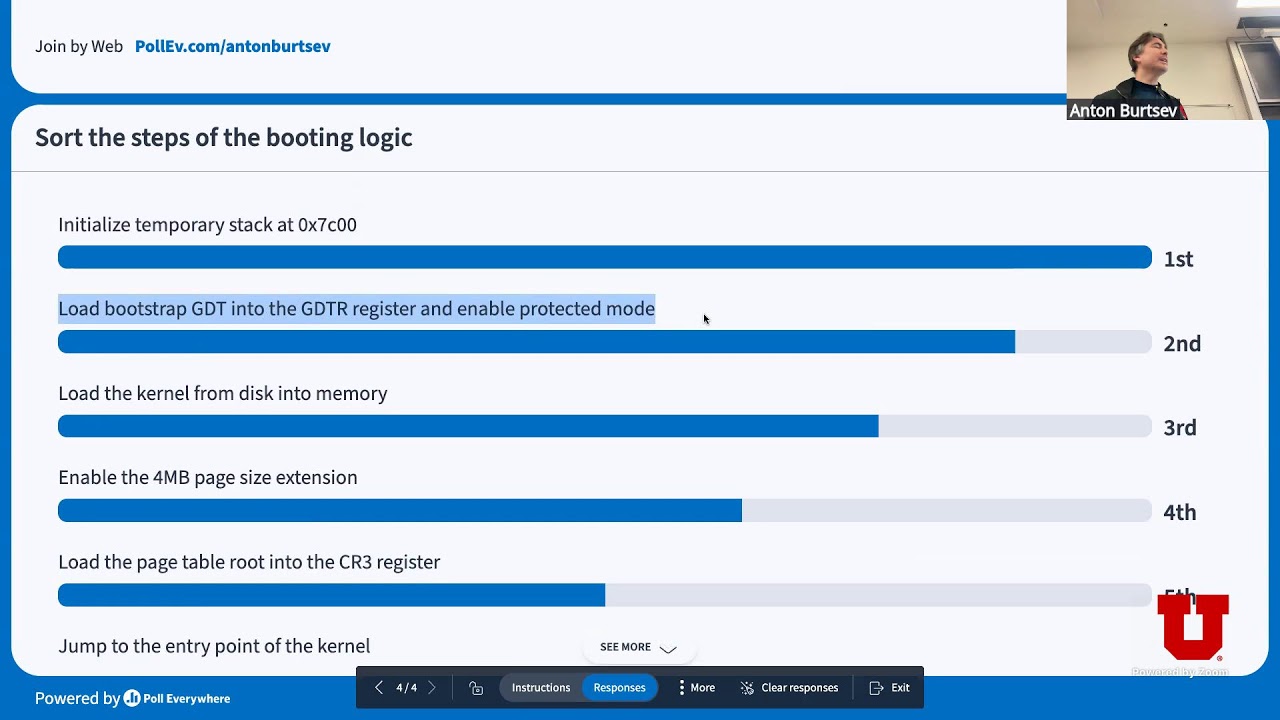









To switch from real mode to protected mode in x86 architecture, you must first define a Global Descriptor Table (GDT) containing segment descriptors for code and data segments, then disable interrupts with CLI, load the GDT with LGDT, set the PE bit in CR0 using a 32-bit register, and perform a far jump to establish the new segment; this enables 32-bit operation with 4GB memory addressing and memory protection features.
OS Development Tutorial: Entering Protected Mode & GDT
Added:Basics of x86 Assembly language, including registers, memory segmentation, and common instructions like MOV and JMP.
Understanding x86 Real Mode and the 'Segment:Offset' memory addressing scheme which is limited to 1 MB.
The PC boot sequence, specifically how the BIOS loads and executes a 512-byte boot sector at memory address 0x7C00.
Familiarity with hexadecimal, binary representation, and bitwise operations, which are essential for defining GDT structures.
Setting up the Interrupt Descriptor Table (IDT) to handle hardware interrupts and software exceptions in 32-bit mode.
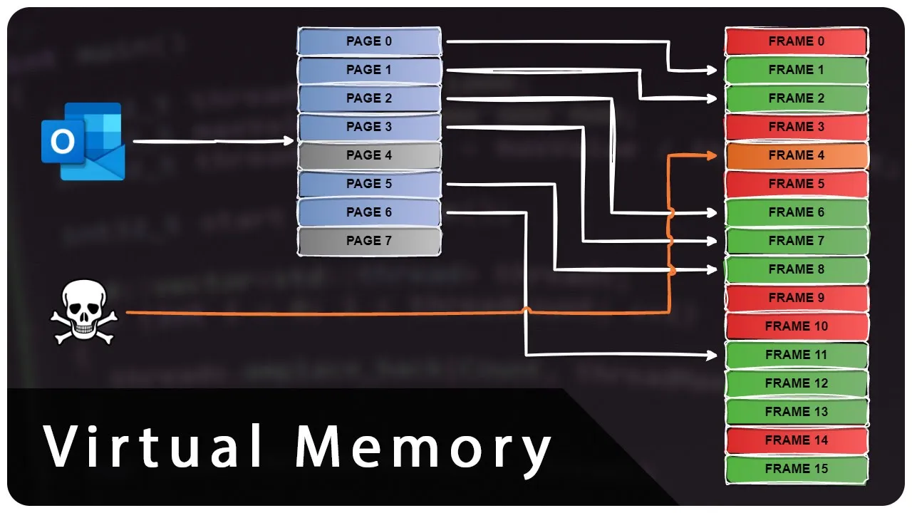
Implementing Paging to transition from physical memory mapping to virtual memory management.
Transitioning from pure Assembly to C by setting up an i686-elf cross-compiler and loading a higher-level kernel.
Developing a basic VGA video driver to handle text rendering, scrolling, and cursor control dynamically.
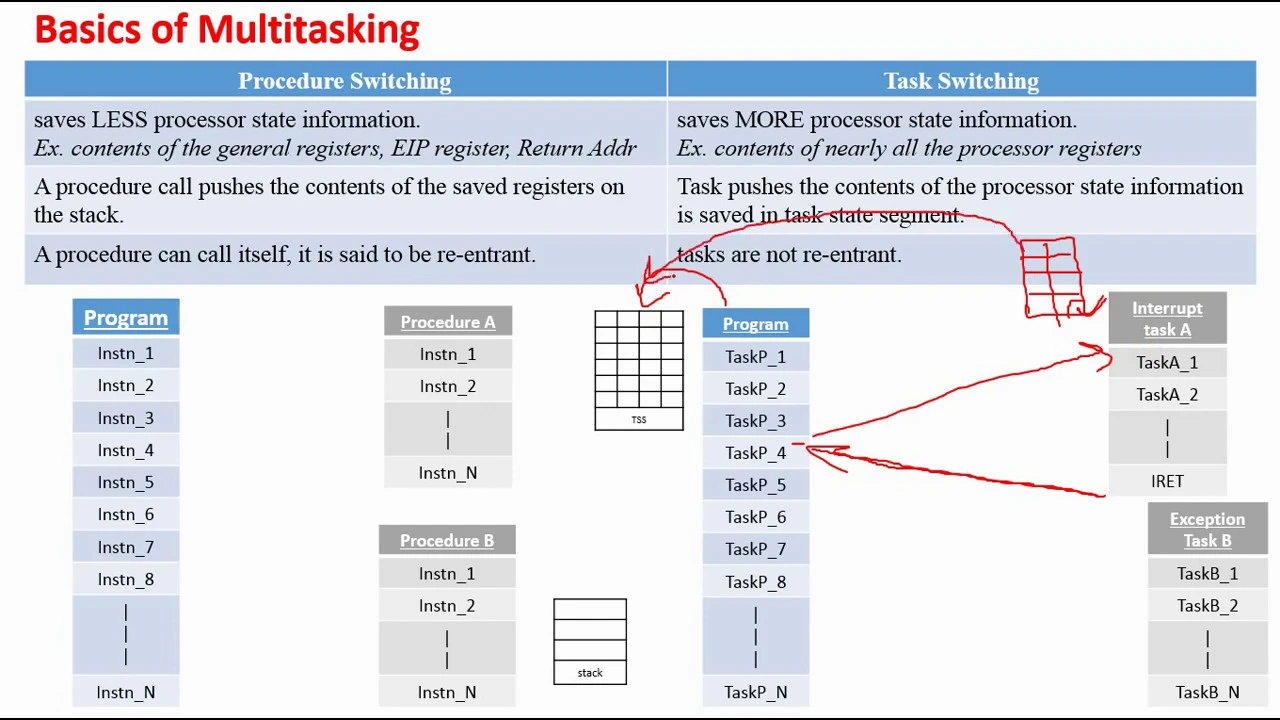
Exploring User Mode (Ring 3) and implementing Task State Segments (TSS) for context switching and multitasking.
71.9K views1.8Klikes11:28Original Release: 2021-08-15
in today's episode we're finally going to switch from real mode to protected mode which is a necessary step towards writing a 32-bit kernel before diving into it i would like to announce that i now have a personal website which i will use to better organize my projects and showcase them to more people in particular part of my website is dedicated to melodrone the kernel i'm working on i think it's important to have a professional website for your projects as it is the best way to make a mediocre project like mine seem a bit more serious so that when the imposter syndrome kicks in you start treating your own projects a bit more seriously if you two want to have a professional website you're in luck because this video is sponsored by hostinger hostinger offers a great deal of high quality services like their premium shared hosting service which already comes at a very very affordable price but along with all the other yearly hosting plans can be discounted up to 91 if you use the coupon code dzlus or the link conveniently situated in the description box their plans offered some very interesting features like free domain name and free ssl and 30-day money-back guarantee once you choose a plan and complete your order setting up the website is very simple you just need to claim your free domain in my case i chose dot com just because i wanted to make this joke good morning activated after all these years click on setup and follow a few simple steps [Music] once you're done with that you can activate your ssl certificate and have a look at the h panel here you can find some very important settings manage your backups and free email accounts in my case i have good morning at mrdalyard.com which to be honest makes me a tiny bit happier than it should the thing that surprised me about herstinga is the insane amount of tutorials and documentation they provide for free so yeah check them out take a moment to think about how useful bios functions are there is one to print a character there is one to read a character from the keyboard there is one to read from the disk there is one to change display mode there are several bias functions that can be used to detect how much available memory we have it would be a shame if we say couldn't use them anymore for some reason and the reason i'm saying this is because today we will be switching to protected mode and we won't be able to use base functions anymore from now on it's not going to be as relatively simple as it was in real mode but first of all why are we switching and what is this protected mode thing protected mode is a 32-bit operational mode so we can address up to four gigabytes of memory we can implement things like paging and multitasking although we're not going to do it in this series also we're going to write in c which is a very good thing so it should be pretty much obvious why we're switching so how do we do it first of all before we switch into protected mode we need to define how segmentation is going to work after the switch so we just need to set a couple of registers to certain values right no no not really you see segmentation works in a bit of a different way in protected mode every segment has a set of permissions and properties that we need to set in a data structure called the global descriptor table or gdt the structure of the gdt is a bit of a mess let's first talk about it with some degree of abstraction and then we will move to the actual definition of the structure we need to define a descriptor for each segment we're going to use in protected mode a descriptor is nothing more than a list of properties of our segment there are several memory management models and techniques to choose from at this point the most common being paging and you might want to read about the pros and cons of each model yourself the one we're going to use is very similar to the tiny model we used in real mode and it's called the flat memory model the key part of the flat memory model is that we will treat memory as a single contiguous address space so we're not really going to use segmentation the thing is the gdt must contain at least a description of the data and code segments so that is what we're going to define let's talk about the code segment first the first thing we need to define is the size of our segment and its location in memory the two properties that we're interested in are called base and limit the base of a segment is the 32-bit property that describes the starting location of our segment in our case location 0 while the limit which describes the size of our segment is a 20-bit property and in our case we should set it to the maximum number that can be represented with 20 bits the next properties are called present privilege and type present is a single bit and it is one if the segment is used so it should be one for every valid segment privilege is a two bit value from zero to three this value is used to define sort of a segment hierarchy and implements memory protection the highest privilege is 0 so we should set it to 0.
type is another single bit that should be set to 1 if the segment is the code or data segment this is the code segment so we're going to set it to one the other properties of the segment are stored as flags a flag is a single bit that represents a boolean property we have two sets of flags both four bits long the first flags are the type flags we will examine them bit by bit the first boolean property is will this segment contain code this is the code segment so we need to set this to 1.
the second property is called conforming and it asks can this code be executed from lower privileged segments as this is the highest privileged segment we should set this bit to zero then we have readable can this segment be read or is it only executable if we set this to 1 we will be able to read constants defined in our code last bit is accessed this bit is used by the cpu it is set to 1 when it is using the segment we should set it to 0 and let the cpu do its thing the other flags are the following granularity when this bit is set to one the limit is multiplied by hex one zero zero zero so we can span a whole four gigabytes of memory this is a good thing so we should set it to 1. the second flag is is this segment going to use 32-bit memory yes so we set it to 1.
we're not going to use the last two bits so we'll set them to 0.
that's all we need for the code segment the data segment descriptor is similar we only need to change a few flags the first type flag should be zero as the segment does not contain code the second one is not the conforming flag anymore but the direction flag when this flag is on the segment becomes an expand down segment that grows downwards we don't want that so we'll set it to zero what was the readable bit in the code segment descriptor is now the writable bit it should be set to 0 if the segment is read only but it is not so we'll set it to 1.
in order to define the gdt in assembly we need to define each of these properties in a certain order to do this we will use the 2 instruction dw or define word that defines two bytes and dd define double word that defines four bytes first of all let's put a label at the beginning of our gdt its purpose will be clear at the end then at the beginning of a rigidity there must be an empty descriptor to define it we just need to define eight zero bytes then we should define the code descriptor here comes the confusing part first of all we need to define the first 16 bits of the limit then we need to define the first 24 bits of the base then we need to define the present privilege and type properties that we can define as a four bit structure and the type flags which together have a size of one byte then we need to define the other flags four bit long and the last four bits of the limit which are all ones finally we need to define the last 8 bits of the base we can do the same for the data segment descriptor the gdt is defined so we can write an end of ddt label but we're not over yet we need to define a gdt descriptor with two entries the first being the size of the gdt that we can calculate by doing end minus start minus one and a pointer to the beginning of the gdt as you can see i added some labels at the beginning of each segment descriptor i can now use them to calculate the offset of the segment descriptor relative to the beginning of the gdt we are now ready to switch to 32 bit protected mode first of all we will need to disable all interrupts by using the cli instruction then we can load the gdt this can be done easily by using the lgdt command then to make the actual switch we need to change the last bit of a special 32-bit register call cr0 to 1. in order to do this since we cannot change the value of this register directly and we can only set it to the value of another register we need to use a 32-bit general purpose register these registers are eax ebx ecx and edx where e should stand for extended the 16 bit general purpose register we use until now are just a part of these registers the lower 16 bits what we can do to change cr0 is we can move it to eax perform a bitwise or operation with one which changes the last bit of eax to 1 and move eax to cr0 once we have done this the cpu is in 32-bit protected mode we're almost there what we need to do now is perform what's called a far jump which is a jump to another segment in this case to our new code segment of set it by some label we now need to define our label we called it start protected mode and since we are in 32-bit mode we should write bits 32 before the label it was not that easy but we made it we are in 32-bit protected mode how do we check well we might do the good old trick and bring a character to screen but oh no we don't have bios anymore so we now have to write to video memory directly this is not that hard since we know that in text mode video memory starts at hex b8000 and that we just need to write to adjacent bytes one for the character we want to print and the other one for its color yes we do have colors now so if we want to print a white on black a to screen what we need to do is for example set al to a ah to the color code for white on black which is hex zero f and move ax to the beginning of video memory as you can see it does print a letter a with a slightly different color so we most definitely are in 32-bit protected mode in the next video we're going to switch to c and for now i'm just leaving you a quite broad exercise have a look at the os dev wiki page in the description and try and experiment with various text and graphics modes if you manage to do something interesting tell us in the comments [Music]
Up Next
58:43
Anatomy of Cross-Compilation Toolchains | Embedded Linux Tutorial
@LinuxfoundationOrg
33.8K views•2017-04-04

87:26
Introduction to Secure Multiparty Computation with Yehuda Lindell
@fhe_org
7.7K views•2021-02-04

7:23
Build an OS: Cross Compiler, Bootloader & Kernel in C
@DaedalusCommunity
78.5K views•2021-08-28
19:25
Enigma Machine Mechanics: WWII Encryption Explained
@JaredOwen
13.2M views•2021-12-11
Related Study Plans & Knowledge Roadmaps
Structured learning paths in Computer Science
computer-science
Container Runtimes: Namespaces, Cgroups & Go
01Linux Systems & Go Programming Foundations
02The Core of Isolation: Chroot and Filesystems
03Linux Namespaces: Process Isolation
+ 3 more learning modules
32h6 modules
Explore Roadmap
computer-science
Building a CHIP-8 Emulator: Rust & CPU Basics
01Computer Architecture Foundations (Bits & Bytes)
02Rust Programming for Systems Development
03CHIP-8 Virtual Hardware Specifications
+ 2 more learning modules
32h5 modules
Explore Roadmap
computer-science
Building BitTorrent: Go, P2P & Concurrency
01Go Fundamentals & Concurrency
02Networking Foundations & P2P Architecture
03Bencode Parsing & Torrent Metadata
+ 3 more learning modules
26h6 modules
Explore Roadmap
computer-science
Actor Models (C++ Concurrency & Lock-Free)
01C++ Multi-Threading Foundations
02Thread Pools and Task Scheduling
03Atomics and Lock-Free Queue Design
+ 3 more learning modules
45h6 modules
Explore Roadmap