











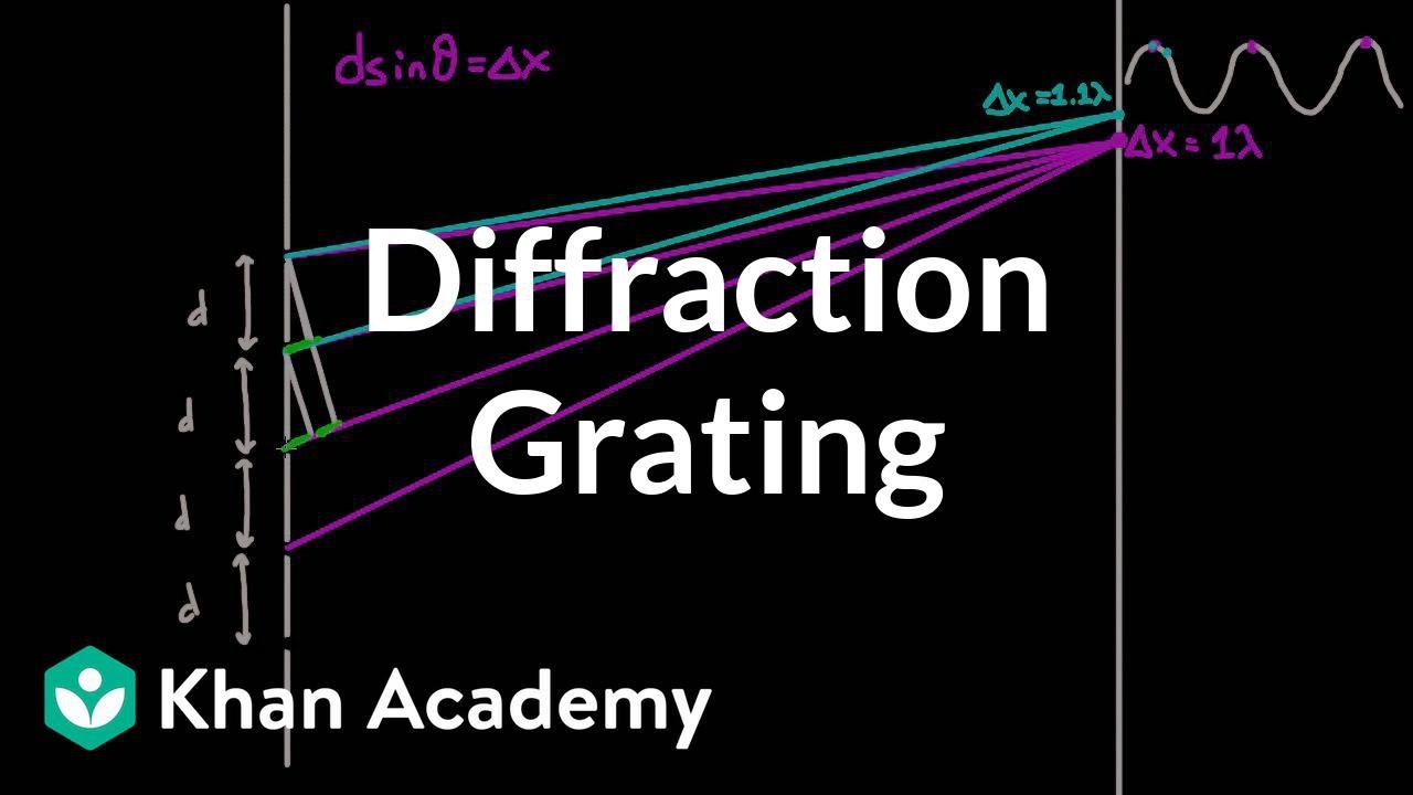








Light can be measured using a homemade diffraction grating printed on transparency film with a laser printer, where the spacing between diffraction fringes follows the relationship λ = xd/L, allowing calculation of the wavelength (approximately 670 nm for red light) from measurable distances between fringes, the distance from the grating to the screen, and the known grating spacing.
Measure Light Wavelength at Home Using Homemade Diffraction Grating
Added:Understanding the basic wave properties of light, specifically wavelength, frequency, and the speed of light.
The phenomenon of wave interference, focusing on constructive and destructive interference caused by path-length differences.
The concept of diffraction, particularly how light waves bend and spread when passing through narrow apertures or periodic structures.
Basic geometric trigonometry, specifically using tangent and sine functions to calculate angles from physical distance measurements.
Deriving and mathematically applying the diffraction grating equation (d * sin(theta) = m * lambda) to solve for grating spacing or wavelength.
Exploring the principles of optical spectroscopy and how diffraction is used to identify chemical elements through emission and absorption spectra.
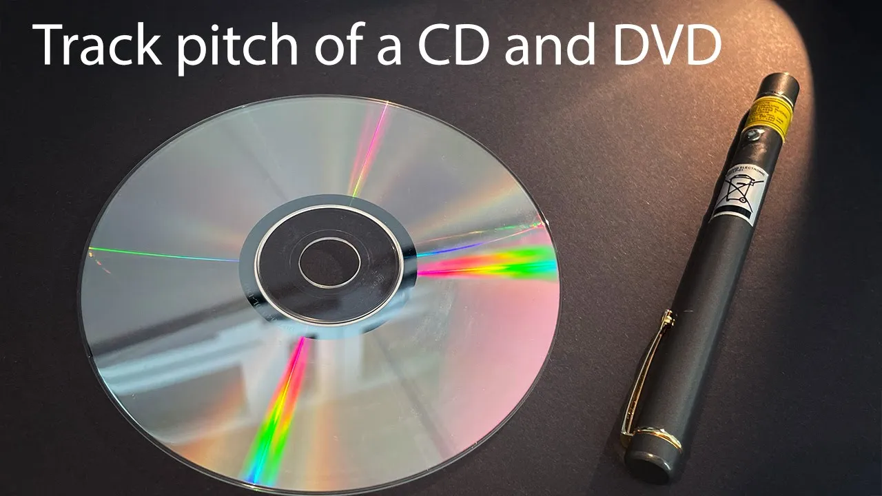
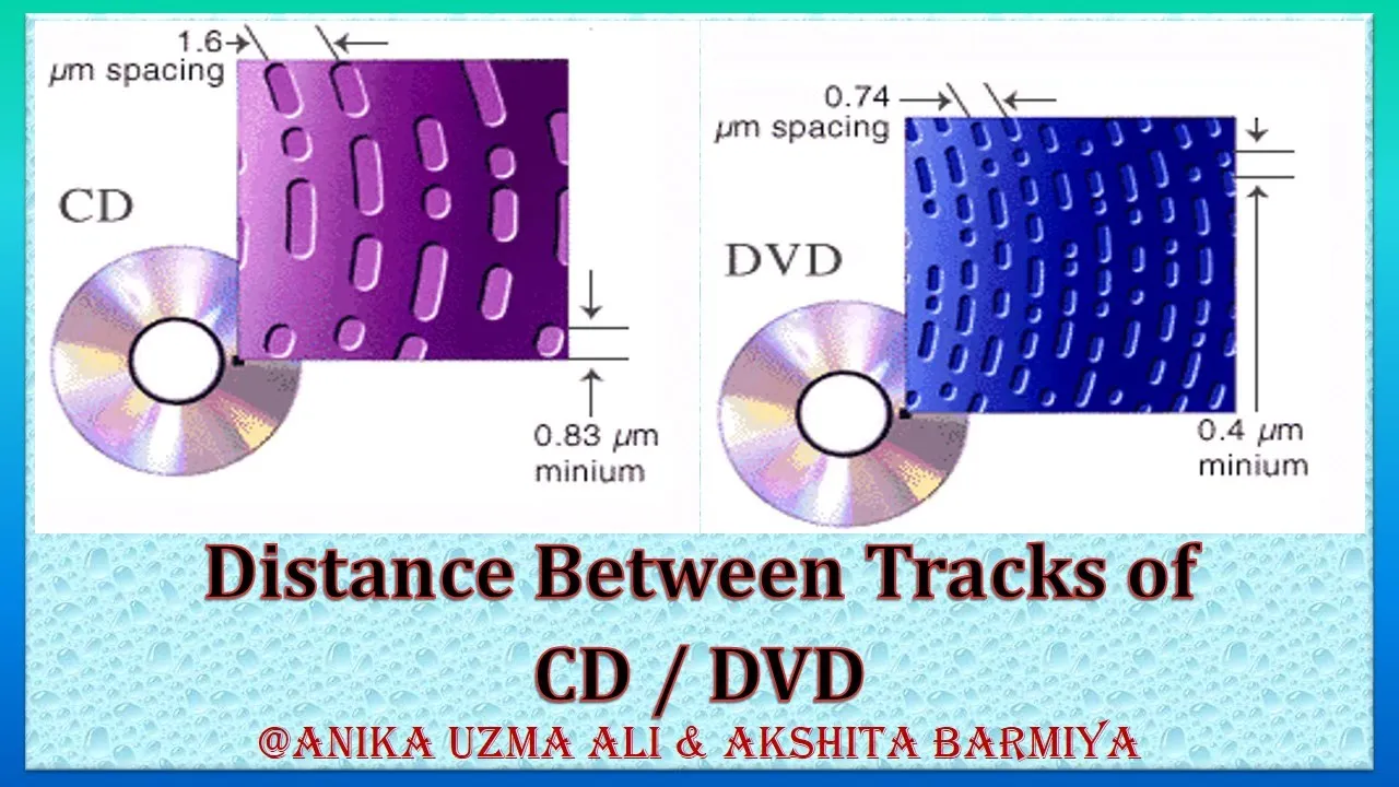
Using the experimental setup in reverse to measure micro-structures, such as calculating the track pitch of a CD or DVD.
Transitioning to Bragg's Law and X-ray crystallography to understand how atomic lattices diffract high-energy electromagnetic waves.
27.4K views1.1Klikes26:48Original Release: 2024-03-17
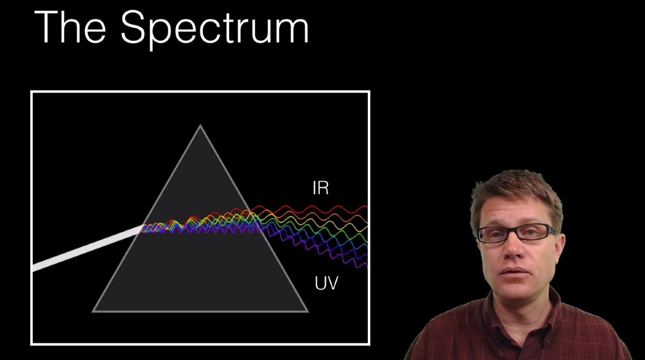
in this video we're going to measure the wavelength of light now anyone can do it with a lab full of equipment but I'm going to show you how to do it with nothing other than stuff that you probably have lying around your home or office getting the wavelength of light is a bit of a challenge because it is so tiny and it may be obvious that because we use light to see things we can't use it to actually see its own wavelength so we have to be a little bit sneaky and set up a situation where we can see the effects of light having a wavelike nature and from that figure out its wavelength and to do that we're going to use a defraction grading so what's a defraction grading well it's a small clear section of something like glass or transparent plastic with a whole bunch of black parallel lines on it or alternately a whole bunch of clear parallel slits on it and those lines or slits are very narrow very fine so find that they're some small multiple of the wavelength of light itself and because they are so close to the wavelength of light it means we do get some weird interference effect and that's what we're going to be using now you can certainly go online and buy some defraction gradings from any number of online retailers from anywhere 20 bucks to probably over a hundred and those will be very nicely built but it's really not very satisfying if you have to go out and buy something fancy to do a experiment like this it would be much neater if we could make a defraction gradient at home and I was wondering if we could use something like a common laser printer to do just that and I actually did some looking in some of the online physics forums and a few people had discussed it but I couldn't find anywhere where someone had actually tried it so I did and to put things in context I'm going to use a 20-year-old HP LaserJet printer and and at that time common laser jet printers including this one had a resolution of 600 DPI that's 600 dots per inch meaning in theory we could draw 600 pixels per inch on our piece of paper so all we need to do is make a picture of a grating with alternating one pixel wide lines of black and then white and repeat that over a certain area and send it to the printer not quite that easy because it turns out if you're using an operating system like Windows or any of the other common ones you have a printer driver in between you and the printer and on top of that you're going to be probably using a program like Photoshop or some sort of paint program and by the time all of that's done if you try and draw a whole bunch of very nrow lines alternating at 600 DPI it's very hard to be sure whether they're going to get lined up with the pixels on the laser printer itself after all that processing and if they're not you're going to get some sort of weird gray mixture of those lines and not a very satisfactory result so what I had to do was do a bunch of things to get around all of that mess and the first thing I did was write a little Java program that would connect directly to the networked printer port at Port 9100 of the laser printer meaning it was not going through any of the Windows printer drivers at all but simply talking directly to the printer and that's not too hard a thing to do if you know how but the harder thing was now having to figure out what to send the printer and HP printers use a printer language called HP PCL which is how all the drivers actually talk to the printer and it does have commands for drawing images very primitive images that are simply pixels that are on or off but you can draw them at 600 DPI in the case of my printer and of course those pixels are the exact pixels that the printer eventually prints out to the paper or in our case a transparency sheet well after a whole bunch of frustrating experimentation I was able to do it and I created a raster image in hpcl of a whole bunch of single Pixel wide black lines beside a whole bunch of single Pixel wide white lines alternating and I sent that to the printer and and here's what I got a nice black Square well what's going on here it turns out that the actual particles in the toner are so big that when you draw a one pixel wide black line the particles in the toner actually spill over into the white space left or right of that line and they spill over so much that if you do what I did you essentially get no white space left it pretty much clogs those thin white lines that I so nicely created well okay 600 DPI doesn't work it's pretty easy to tell the printer just print that at 300 DPI and sure enough we now get a nice pattern of somewhat thicker black lines than white lines but we do have a defraction grading but not as fine as I'd hoped and I want it to be as fine as possible so one more attempt and that was to say what happens if I draw two white lines next to each other then one black line and then two more white lines and so forth so the white lines were essentially twice as thick as the black line well do that and print it at 600 DPI and here's what I get yes it is probably about as fine a defraction grading as I can draw with this printer and if we look at it under the microscope it's not too bad in terms of size of those white slits which is what's really important to us you'll notice that the whole thing is pretty crude but you'll be surprised how well that'll actually work when we try it so for the laser we'll use an old IR laser thermometer that I had lying around and I'll clamp it into a la and& Decker workmate and point it towards the wall of my workshop and turn it on by using some electrical tape to keep the trigger depressed and surprise surprise we get a nice Red Dot on the wall the interesting part is when I take the defraction grading that we printed and position it so that it is between the laser and the wall and we suddenly get a nice series of red dots instead of just the single dot we originally had that shows us that the defraction grading has taken the light and maybe quite surprisingly split it off into a bunch of beams each going out at a slight angle to the original and it turns out that the angle that they're split off is directly related to the spacing of the lines in our defraction grading and the wavelength of the light at this point what I'd like to do is take some measurements from this which we'll use later to actually determine the wavelength of light so what I did before I made the video is I set things up so that the laser is 2 m away from the wall so all we really have to do is measure the spacing between the dots and if I take a tape measure and put it near the dots it looks like the dots are about shall we say 10 mm apart or so maybe what we'll do is try and measure the distance between two of the dots to get something perhaps a little bit more accurate and if I look at it at least from here it looks to be maybe 21 mm or something like that so what that probably means is a spacing of about 10.5 mm between the dots is the best estimate we can get using this very crude setup okay so I said I would show you why we get that splitting of light into multiple beams and that's what we're going to do right now we'll start off with a very simple setup where we have a defraction grading this black line with a single small hole in it and a red laser pumping out nice parallel waves until they hit the defraction grading and the defraction grading has just a tiny slit and when the light hits that slit while when it gets to the other end it comes out and forms nice circular waves just like we would get when we throw a pebble in in a pond and in this diagram I'd like to consider the red lines to be the crests of those waves and the distance between the red lines or those crests is the wavelength which we'll denote as Lambda but of course one hole doesn't really represent our defraction grading very well so what we'll do is consider the case of two holes or two slits and I can say slits because we're looking at the from above looking down so this is the edge of that defraction grading now we have two slits one two the second slit is shown in Orange but it's not like it changes the wavelength of light from red to orange or anything like that I've just used orange to make it clear which ones of these waves come from which slit and just like the first slit we have nice circular waves coming out of the second slit and what's really interesting is where the crests of those waves hit or intersect well they add together and if the crests of these waves are the same height where they overlap they add and now we have a little point of a wave a crest of a wave that is in fact twice the height of the original waves and if we consider the white areas between the crests as the trough or the valley of those waves well if we have a orange Crest hitting a red Valley they add together and when you add them together you get nothing they cancel out so that is destructive interference this is constructive interference and what you can see here is there's 1 2 three points where we clearly have constructive interference in a line and if you imagine these waves are moving out in their semicircles Well what we'll get is in fact a line of nice bright constructive interference and what that is indeed is a nice straight beam of light that's going out straight ahead essentially the continuation of our original laser beam in other words that original dot that we saw on our screen the dot in the center when we had multiple dots but it's kind of unclear what happens at Angles and even for that matter how this Center interference ends up really in a continuation of these parallel waves so to make it a little bit clearer what I'm going to do is replace this diagram with one that only shows pi-shaped sections of these circular waves so we can get a clearer idea of what's going on okay so now with the somewhat reduced amount of waves what we can sort of see is these waves here sort of continue on a straight line and you can imagine if we had another hole in our defraction grading here we'd have another wave that sort of continues this and same thing on this side and same thing for these waves again something like that and what you would expect to get is a nice straight series of parallel waves coming out essentially the continuation of our original laser beam down here just continuing straight up to our original point and it is worth pointing out that indeed if we do have a whole bunch of these holes or slits in our defraction grading on either side many of them tens preferably hundreds or thousands it turns out if you work through all the math you indeed get nice straight parallel waves and all the sort of wobbliness disappears but we won't bother with that math in this video so that's all very nice but what about the wave that started going off on a direction like that well once again what we'll do is use some pi-shaped sections of wave but we direct them a bit like that so once again we can see what's going on the waves coming out of our two holes just showing the parts that we're interested in and if we take our transparency sheet and try and line up its nice parallel wave crests to the semicircular ones what you can see is over here they match up quite nicely and once again if we had a whole bunch of holes it would all work out so that these slightly wobbly combinations of wave fronts indeed become nice and parallel the interesting thing is if we look down here and we follow this Crest here from this slit and the defraction grading over to the next well this distance here is one wavelength and so that's the key to how we're going to figure out what the wavelength of light is we know what this angle is and we know what this distance is it's the distance between the slits and the defraction grading and so we should be able to calculate the wavelength over here we can take this one step further try an even bigger angle once again we'll try and line up our transparency sheet nicely with the semicircular wave fronts that we're dealing with that's about it here and sure enough watch what happens when we follow the hopefully parallel Crest that goes through this defraction grading hole up here well how far is it from the next defraction grading hole it's one two wavelength so that's the pattern each one of the off-center dots of light that we see on the screen corresponds to an increasing shift of these parallel waves from the next over defraction grading Hole by one wavelength so if you have a background in antennas and think you've seen this somewhere before well this is indeed a phased array antenna each of the holes or slits in the defraction grading corresponds to an antenna and when it's angled like that it's effectively equivalent to beam steering if you have a mathematical background the slits in the defraction grading correspond to a periodic function and the bright points that we see on the observation screen are the magnitude squared of the fora transform of that periodic function now you've seen why we get that pattern of dots or most obviously why we get the dot immediately to the left and right of the center dot when we insert the defraction grading but using what we've done let's take a look at now how we can actually calculate the wavelength of light based on the dot spacing and the distance from the defraction grading over here is our screen or the wall that I use to see the dots of light and down here is the defraction grading with its various holes and what we'll do is take an interest in this hole and say we have a nice straight ray of light ending up here and this is of course our Bright Center Spot the spot that we got when we didn't have a defraction grading at all now on our screen we also have some smaller spots some dimmer spots I should say on each side and one over here and we'll take an interest in the first one and once again we'll draw the ray or beam of light corresponding to the first off center dot like this and we might as well put in a few things that we know we know the distance between these two dots which we'll call X and which we decided was 10.5 mm when we measured it we'll also make a note of what this distan is and really this distance or this distance is actually pretty much the same because this angle is really very small so this picture is highly exaggerated but anyway what we'll do is we'll say this distance over here is L and it is 2 m 2,000 mm well that's very nice what we should really do now is see if we can somehow use these angles to figure out the wavelength and if we were to take this beam here and make a beam at right angles to it or make a line I should say at right angles to it we'll get something like that and maybe what I'll do is do that to denote these things are at right angles we should also point out that this angle over here is of importance it's called Theta and because this is at right angles and this is at right angles this angle over here is also Theta okay well what we're really interested in is this distance over here and I'll try and draw a line parallel to that one this dotted line corresponds to the crest of the wave that's coming through this slit and is one wavelength away from the next slit so that distance is wavelength or Lambda and there's one more thing we need to know and luckily we do know it and that is the distance between our slits in the defraction grading and that distance is7 micrometers and we'll call it D okay so it should be pretty easy now to figure out what that is because these triangles are similar triangles so we can write down a nice simple equation the short side over the long side Lambda over D is equal to the short side x over the alongside L of the big triangle and we're of course interested in Lambda so we'll multiply both sides by D Lambda equal x * D over L and we can now just fill in the values of all of these things I'll write it on the other side so there's some space Lambda equal x well X is 10.5 mm time d d is 127 micromet or 0.127 mm all divided by L and L is 2,000 mm and if we put that all into a calculator what we get is 0.0000 667 MIM and if we move the decimal point six spaces what we get is Lambda is equal to 667 nanometers and you know that's really Way Beyond the accuracy that the crudeness of this experiment gives us so we'll just get rid of the last position here and say Lambda equals 670 nanom so there you have it 670 nanom not bad at all compared to the 630 to 670 nanometer specification for the red laser on that our thermometer if we'd bought a fancy defraction grading with a finer pattern the dots on the wall would have been further apart and would have been easier to measure and we probably would have gotten a more accurate result but I'm quite thrilled with how well we did given how crude the homemade defraction grading was now if you found that interesting a few months ago I did a similar video on how to measure the speed of light and there should be a big rectangle up there that will lead you to it if you click on it I should also point out in both videos we use lasers and a word of caution never ever let a laser beam get in your eye or anybody else's or even a reflection from something like the piece of plastic we use to make the defraction grading it can lead to severe eye damage so please be careful as always well that brings this video to an end I hope you enjoyed it and see you next time
Up Next
13:44
Constructive & Destructive Interference | Physics Lesson
@khanacademyphysics7609
469.1K views•2016-07-29

12:53
21cm Hyperfine Transition in Neutral Hydrogen: Radio Astronomy Basics
@AaronRobertParsons
12.4K views•2011-10-13

32:32
NMR Spin Physics I: Zeeman Effect, Resonance Condition & Larmor Frequency
@nptel-indianinstituteofsci8064
2.3K views•2024-01-17

27:14
Entropy and the Second Law of Thermodynamics Explained
@veritasium
27.5M views•2023-07-01
Related Study Plans & Knowledge Roadmaps
Structured learning paths in Physics
physics
Nuclear Physics (Decay, Fission & Reactors)
01Atomic Structure and the Binding Force
02Radioactive Decay and Half-Life
03Nuclear Fission Mechanics and Chain Reactions
+ 2 more learning modules
12h5 modules
Explore Roadmap
physics
Soft Matter (Polymers, Colloids & Rheology)
01Foundations of Soft Matter & Thermal Forces
02Polymer Physics and Macromolecules
03Colloids, Surfactants, and Self-Assembly
+ 2 more learning modules
38h5 modules
Explore Roadmap
physics
Analytical Mechanics: Lagrangian & Hamiltonian
01Mathematical Foundations: Calculus of Variations
02From Newtonian Mechanics to Constraint Dynamics
03The Principle of Least Action & Lagrangian Mechanics
+ 3 more learning modules
28h6 modules
Explore Roadmap
physics
General Relativity (Spacetime & Cosmology)
01Foundations of Relativity: Special Relativity
02The Geometry of Spacetime: Equivalence Principle & Curvature
03Einstein's Field Equations: The Mathematics of Gravity
+ 2 more learning modules
55h5 modules
Explore Roadmap