Wings generate lift primarily by deflecting air downward, which creates an equal and opposite upward force according to Newton's Third Law; while the traditional explanation involving Bernoulli's principle (that faster-moving air over the curved upper surface creates lower pressure) is partially correct, it oversimplifies the mechanism by incorrectly assuming air particles on both sides of the wing must meet at the trailing edge simultaneously.
How Airfoils Generate Lift: Physics Explained
Added:Deep Dive
Newton's Laws of Motion, particularly the Third Law (action and reaction) regarding force pairs.

Newton's Laws of Motion
185
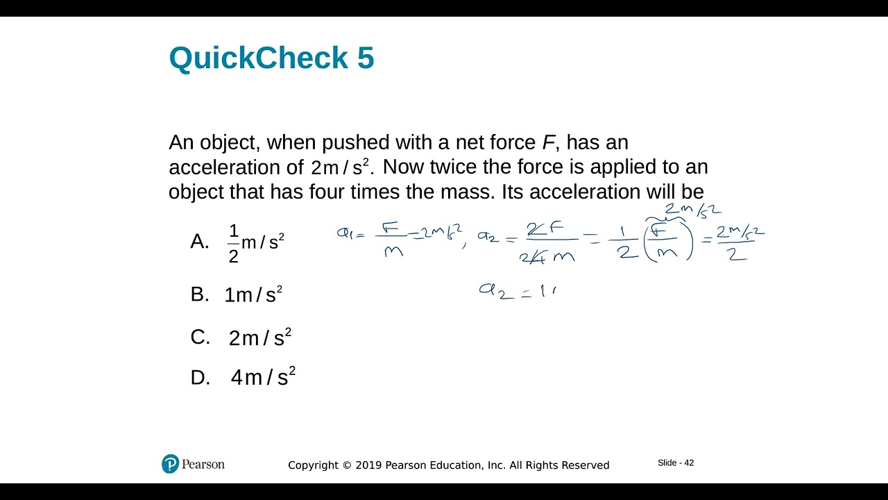
Newton's Third Law states that for every action force, there is a reaction force that is equal in magnitude and opposite in direction. This is also known as the law of force pairs. A force pair consists of two forces that represent an action and reaction, and they must act on two different objects - they cannot act on the same object.
Click to watch →
Newtons laws
122
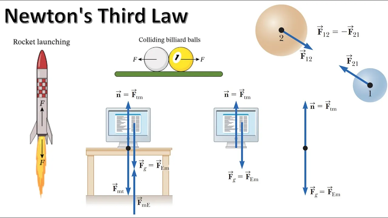
Newton's Third Law states that for every action force, there is an equal and opposite reaction force. Forces always occur in pairs: if object A exerts a force on object B, then object B exerts an equal and opposite force on object A. These action-reaction pairs are always equal in magnitude and opposite in direction, regardless of the sizes of the objects. Examples: walking (push back on ground, ground pushes forward), rocket propulsion (push gases backward, gases push rocket forward), mosquito hitting truck (same force on both, but different accelerations due to different masses).
Click to watch →
5.6. Newton's Third Law_Part 1
138
Newton's Third Law states that for every action, there is an equal and opposite reaction. When two objects interact, they exert forces on each other that are equal in magnitude but opposite in direction. These forces always occur in pairs between two different objects. Action-reaction pairs must be of the same type of force (e.g., both gravitational or both contact forces). The law can be expressed mathematically as F₁₂ = -F₂₁, where the negative sign indicates opposite directions. This fundamental principle explains why forces always come in pairs and why isolated forces cannot exist.
Click to watch →

Physics 4 Newton's Laws of Motion (3 of 20) What is Newton's Third Law?
85.7K
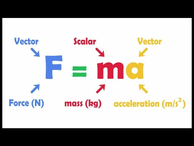
Newton's Third Law states that for every action force, there is an equal and opposite reaction force. Forces always occur in pairs with equal magnitude and opposite direction. When a person pushes a wall, the wall pushes back with equal force. Similarly, when feet push against the ground, the ground pushes back. A person's weight pushes down on the ground, and the ground pushes back with an equal upward force. These action-reaction pairs demonstrate that forces are vector quantities with both magnitude and direction. When all forces are balanced (net force equals zero), there is no acceleration according to Newton's Second Law. However, when friction is removed (like wearing roller skates), the unbalanced reaction force causes acceleration.
Click to watch →
Newtons laws of Motion 01 ll Inertia Linear Momentum ll 11th class ll 1st 2nd 3rd Law ll NEET IITJEE
1.3K
Newton's Third Law states that for every action, there is an equal and opposite reaction. Forces always occur in pairs. Action and reaction forces are equal in magnitude, opposite in direction, and act on different bodies. This law applies whether bodies are at rest or in motion, and for all types of forces (gravitational, electric, magnetic). Examples include: box on table (weight mg action, normal reaction), walking (push ground backward, ground pushes forward), firing a gun (bullet forward, gun recoils backward), and rocket propulsion (gases pushed down, rocket moves up).
Click to watch →
Deep Dive
Basic fluid dynamics concepts, including pressure, velocity, and how fluids flow around objects.

F2 L 4.1- How do forces act in fluids
100
Fluids are substances that can flow, including both liquids and gases, where molecules move freely and bump into each other. Pressure is the force exerted by fluids through molecular collisions on containers and each other. Unlike solids that move in the direction of force, fluids flow around objects in all directions. This explains phenomena like swimming through water or air flowing around airplane wings, where aerodynamic principles minimize resistance.
Click to watch →
![[English] Concept of pressure , Flow and velocity / Difference between pressure and flow](https://i.ytimg.com/vi/ADnZWIZv3HU/maxresdefault.jpg)
[English] Concept of pressure , Flow and velocity / Difference between pressure and flow
5K
Pressure is the force exerted by a fluid per unit area, flow is the quantity of fluid passing through a cross-section per unit time, and velocity is the speed and direction of fluid movement; these three concepts are fundamental to understanding fluid dynamics and have practical applications in engineering systems like hydroelectric power plants and water distribution networks.
Click to watch →

Fluid Dynamics||Master's Final Year||Introduction
278
Fluid Dynamics consists of two key terms: Fluid (প্রবাহী) and Flow (প্রবাহ). Fluid is a substance that can be stationary (like water in a container), while Flow is always in motion. Fluid can be stationary or moving, but Flow is always moving. Properties calculated include viscosity, density, pressure, and velocity. Flow types are Turbulent (disordered, spreading flow) and Laminar (smooth, orderly flow). The Reynolds number determines flow type—values above 2000 indicate turbulent flow.
Click to watch →
11th Physics|L-6|Bernoulli's Principle| द्रवों की यांत्रिक गुणधर्म (Mechanical Properties of fluids)
8.6K
This comprehensive section covers essential fluid dynamics concepts: (1) Terminal velocity - the maximum constant velocity an object attains when falling through a fluid, given by vt = 2/9 × r² × (ρ - σ) × g / η; (2) Ideal fluid properties - inviscid (no friction) and incompressible (constant density); (3) Types of fluid flow - streamline flow where all particles at a point have same velocity, and turbulent flow with chaotic irregular patterns; (4) Critical velocity - the threshold velocity for maintaining streamline flow; (5) Reynolds number - a dimensionless quantity R = (ρ × d × vc) / η that determines flow type: R < 2000 indicates streamline flow, R > 3000 indicates turbulent flow.
Click to watch →

🧨Mechanical Properties of fluids | Detailed One shot |Notes |Pyqs | Imps |Hsc Board physics |class12
82.1K
Hydrostatic fluids are at rest (water in lakes), while hydrodynamic fluids are in motion (water in rivers). Streamline flow is smooth and orderly, while turbulent flow is chaotic and irregular. The transition occurs at critical velocity. Pressure types include atmospheric pressure (from atmosphere), gauge pressure (above atmospheric), and absolute pressure (total). These concepts are fundamental to understanding fluid dynamics and engineering applications.
Click to watch →
Deep Dive
Bernoulli's Principle and its traditional (though often oversimplified) application to aerodynamics.

UMAT MUSLIM Makin Menjauh Dari SAINS! Dulunya Penguasa! | Learning By Fasting ft Felix Siauw & Risco
890.3K
Bernoulli's principle explains that when fluid velocity increases, pressure decreases. This principle demonstrates that high-pressure air naturally moves toward low-pressure areas. The principle explains how airplanes fly: wing shape creates lower pressure above and higher pressure below, generating lift. It also explains car spoilers, which increase downforce at higher speeds for better traction. The principle applies to everyday phenomena like blowing air through a straw to fill containers quickly.
Click to watch →

7)TYT Fizik - Akışkanların Basıncı - Barış AKINCIOĞLU - 2025
89.5K
Bernoulli's principle explains aerodynamic lift generation. Aircraft wings are designed with curved shapes that cause air to flow faster over the top than below, creating lower pressure on top and higher pressure below. This pressure difference generates lift. Similarly, car aerodynamics use this principle to create downforce, pressing vehicles toward the ground for better traction. Buildings with sloped roofs experience pressure differences when wind flows over them, potentially causing structural damage.
Click to watch →

🔴 LIVE! / ПинКод. Наука с ПинКодом
457.8K
Bernoulli's Principle states that as the speed of a fluid (liquid or gas) increases, its pressure decreases. This principle explains how airplanes fly: air moves faster over the curved upper surface of the wing than under the flatter lower surface, creating lower pressure above and higher pressure below, which generates lift. Bernoulli's Principle also explains why a ping-pong ball stays suspended in an air stream and why airplane wings generate lift.
Click to watch →

Plus One Physics Model Exam - Mechanical Properties of Fluids | Mission NCERT | RK Nex
364
This section applies Bernoulli's principle to real-world aerodynamic phenomena. Bernoulli's equation applies only along streamlines in steady, incompressible, non-viscous flow and cannot be applied to turbulent conditions. Lift on airplane wings results from velocity differences between upper and lower surfaces: higher velocity on top creates lower pressure, while lower velocity below creates higher pressure. The lift force is calculated as F = (1/2)ρA(v₁² - v₂²). For a wing with area 2.5 m², upper velocity 70 m/s, and lower velocity 6 m/s, the lift force is approximately 1.51 × 10^4 N. Velocity and pressure are inversely related in fluids.
Click to watch →

Fluid Mechanics | PART-2 | Concept + Top PYQs | Tricks & Shortcuts | JEE 2025 | Madhan Sir
6.8K
Bernoulli's principle explains how airplanes generate lift. The curved upper wing surface causes faster airflow, creating lower pressure, while the flatter lower surface has slower-moving air with higher pressure. This pressure difference creates upward lift force. The lift force equals the pressure difference multiplied by wing area. For level flight, lift must balance the airplane's weight. This principle also explains why roofs lift during cyclones and why trains pull people toward them.
Click to watch →
Deep Dive
The concept of vector forces, specifically distinguishing between lift, drag, thrust, and gravity.
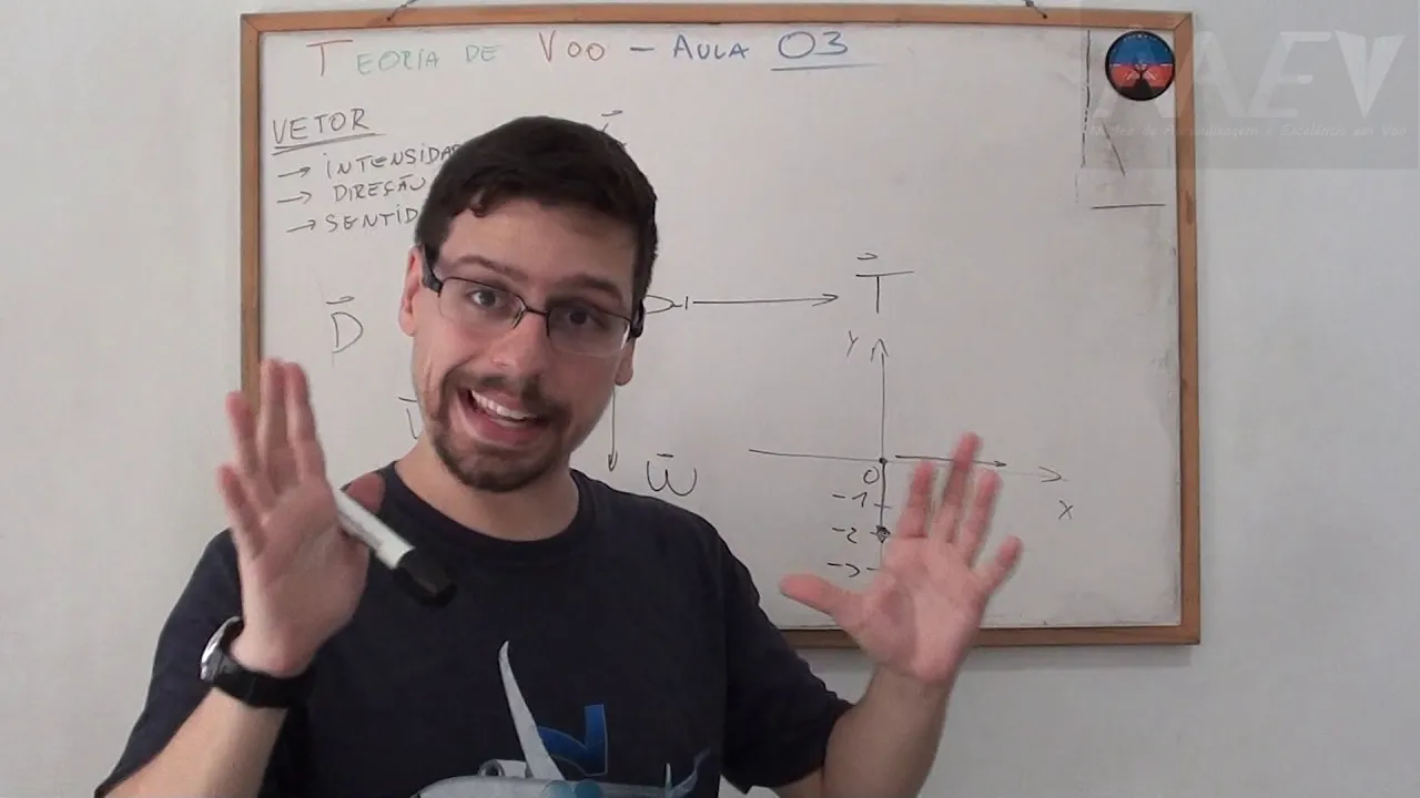
TV: VA03/pt01 Conceito de Vetor e Força
2.8K
In aviation, the four fundamental forces of flight—lift (sustentação), weight (peso), thrust (tração), and drag (arrasto)—are vector quantities that require both magnitude and direction to be understood. According to Newton's laws, for an aircraft to maintain level flight, lift must equal weight and thrust must equal drag, creating force equilibrium. Vectors are distinguished from scalar quantities by possessing three essential components: intensity (magnitude), direction (the line connecting start and end points), and sense (orientation along the direction). This vector-based approach allows pilots and engineers to analyze and predict aircraft behavior during different flight regimes.
Click to watch →

แรงและการเคลื่อนที่ สรุปเนื้อหา+โจทย์ | ป๋ามัก ideal Physics
9.8K
For aircraft problems involving lift and thrust: (1) The lift force (L) acts perpendicular to the direction of motion, (2) The thrust force (F) acts in the direction of motion, (3) The weight (W) acts vertically downward, (4) The forces are related by vector components: L cosθ = W and L sinθ = F, where θ is the angle between the lift force and the vertical, (5) The thrust force is given by F = W tanθ, (6) The lift force is given by L = W / cosθ. The angle θ is determined by the aircraft's flight path and wing orientation.
Click to watch →
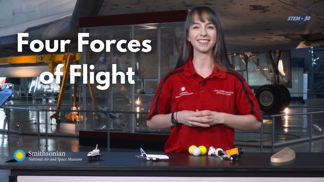
The Four Forces of Flight Explained | Physics of Airplanes
126K
The four forces of flight are lift (upward force generated by air pressure differences over an airfoil), weight (downward gravitational force), drag (backward resistance from air), and thrust (forward propulsion). Lift is created when faster-moving air above a wing creates lower pressure than slower-moving air below, following Bernoulli's principle; weight affects all objects equally at 9.81 m/s² regardless of mass; drag depends on shape with streamlined objects experiencing less resistance; and thrust is produced by propellers, jet engines, or rocket engines that push air backward to move forward.
Click to watch →
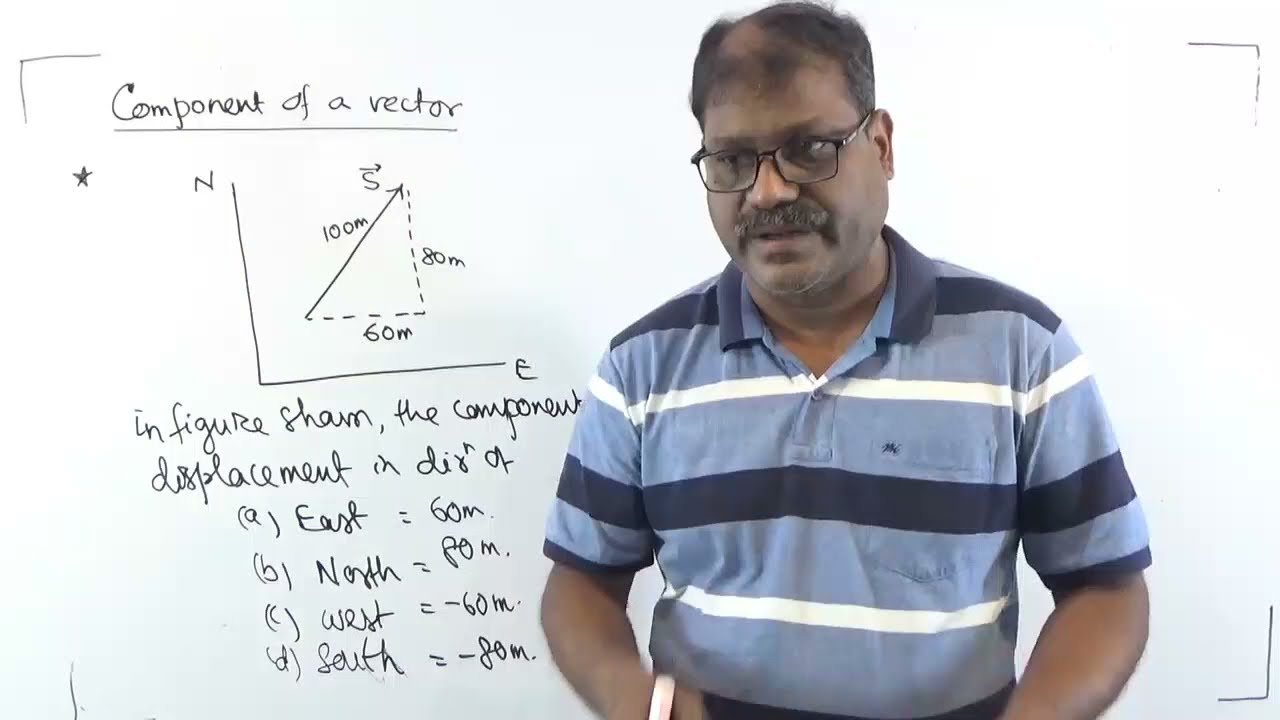
Components of vector IFC IX 2021
298
This segment covers drag force and lift force vectors and their components. The instructor explains that drag force vectors can be resolved into horizontal and vertical components using trigonometric functions. For example, a drag force of 10 Newtons at 30 degrees has horizontal component 8.66 Newtons and vertical component 5 Newtons. Similarly, lift force vectors are resolved using the same method. The instructor emphasizes that these components help in analyzing drag force and lift force in different directions.
Click to watch →

RRB JE 2024 Science Marathon | Complete Science Revision | By Deepmani Sir
159.4K
The force that moves an aircraft through the air is called thrust. Thrust is used to overcome the drag (air resistance) of the aircraft and to overcome the weight of the aircraft. The four main forces acting on an aircraft are lift (upward), drag (backward), thrust (forward), and gravity (downward). Understanding these forces is essential for aviation physics.
Click to watch →
Prerequisite Knowledge
- Concept 01Newton's Laws of Motion, particularly the Third Law (action and reaction) regarding force pairs.
- Concept 02Basic fluid dynamics concepts, including pressure, velocity, and how fluids flow around objects.
- Concept 03Bernoulli's Principle and its traditional (though often oversimplified) application to aerodynamics.
- Concept 04The concept of vector forces, specifically distinguishing between lift, drag, thrust, and gravity.
Subsequent Learning
- Step 01The Coandă Effect and its role in keeping airflow adhered to the curved upper surface of a wing.
- Step 02The relationship between the Angle of Attack (AoA) and aerodynamic stall conditions.
- Step 03Induced drag and the formation of wingtip vortices caused by pressure equalization.
- Step 04The design and physics of high-lift devices, such as flaps, slats, and spoilers used in real-world aviation.
- Step 05Supersonic aerodynamics and how shockwaves alter lift generation at transonic and supersonic speeds.
Wing Lift Myths
Unified Truth
Wing Lift Myths
0:00Playing Section
- 1
Common Bernoulli-based explanation is flawed and incomplete.
- 2
Air streams do not rejoin at the trailing edge, breaking key assumption.
Circulation Theory and the Limitations of Simplified Lift Models
While introductory physics often pits Bernoulli's principle against Newton's laws of motion (air deflection) to explain lift, aerodynamicists argue that both explanations are qualitative simplifications that fail to capture the complete picture. The counterpoint to these simplified models is the Circulation Theory of Lift, formulated via the Kutta-Joukowski theorem. This mathematical framework explains that lift is generated by 'circulation'—a theoretical vortex-like flow superimposed on the fluid stream around the airfoil. Critics of purely Newtonian or Bernoullian explanations argue that they cannot account for why the air curves along the airfoil's upper surface without incorporating fluid viscosity, boundary layer behavior, and the 'Kutta condition' at the trailing edge. From this perspective, trying to explain lift using only simple force deflection or pressure differences oversimplifies the complex fluid dynamics, and only computational fluid dynamics (CFD) and circulation theory provide a mathematically rigorous explanation.
Deep Dive
The Coandă Effect and its role in keeping airflow adhered to the curved upper surface of a wing.

How Does Lift Work? (How Airplanes Fly)
1.6M
The Coanda effect is a phenomenon where fluid (air) moving over a curved surface tends to stay attached to that surface rather than flowing away. When air flows over a wing's curved upper surface, the flow lines remain attached as they pass over the top region and move toward the rear. This attachment is essential for creating the pressure differences that generate lift.
Click to watch →
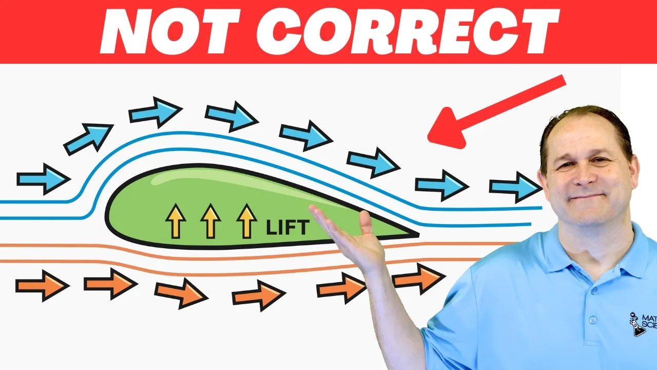
How Airplane Wings REALLY Generate Lift
1.6M
The Coanda effect describes the tendency of fluids to adhere to surfaces and follow their contours rather than flowing straight. When air flows over a curved wing surface, it tends to hug the surface and follow its curvature. This adhesion occurs because of viscosity and molecular interactions between the fluid and the surface. As the airflow follows the curved surface, it gets redirected from horizontal to downward direction. This change in velocity vector requires a force, and by Newton's Third Law, the reaction force provides additional lift. The Coanda effect is responsible for why curved surfaces generate more lift than flat ones, even when both present the same angle of attack.
Click to watch →

Floating objects in a stream of air.. Coanda effect // Homemade Science with Bruce Yeany
35.5K
The Coanda effect describes how an airflow will follow the curve of a surface rather than continuing in a straight line. When air is blown alongside a curved object like a ball or bat, the ribbon demonstration shows that the air actually moves across the top of the object. This curved surface causes the air to bend around it, reducing pressure on the upper surface while atmospheric pressure below provides lift. The effect works best with objects that have sufficient curvature for the air to follow their contours.
Click to watch →

Efecto Coandă #shorts @dateunvlog
325.4K
The Coandă effect is a physical phenomenon where a fluid (such as air) flowing around a curved surface tends to adhere to and follow the curvature of that surface rather than flowing away from it; this effect is crucial for understanding how airplanes generate lift and can be demonstrated using a hair dryer and a ball.
Click to watch →
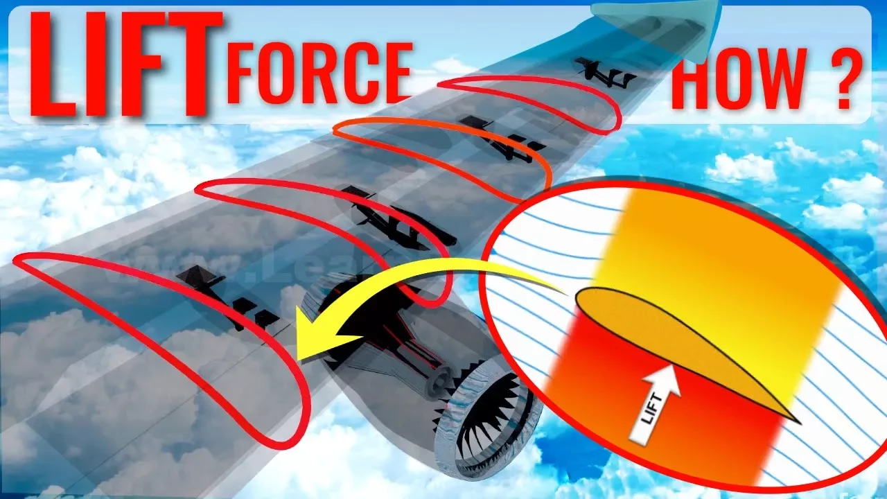
How do Wings generate LIFT?
1.8M
When fluid flows over an airfoil, it follows a curved path due to the shape of the surface. This curvature requires a pressure difference to maintain the curved motion - higher pressure on the outside of the curve pushes fluid inward. For an airfoil, this means higher pressure beneath the wing and lower pressure above, which keeps the flow attached to the surface. The Coanda effect describes how fluids tend to follow curved surfaces, and this natural tendency causes the flow to curve around the airfoil.
Click to watch →
Deep Dive
The relationship between the Angle of Attack (AoA) and aerodynamic stall conditions.

It WOULDN'T Let Them Pull UP!!? | The Strange Story Of Lufthansa Flight 1829
49.1K
Angle of attack (AOA) is the angle between the wing's chord line and the direction of the air impacting the leading edge. As AOA increases, lift and drag build up until the wing reaches alpha max. Beyond this point, airflow breaks away from the wing surface, causing lift to collapse and drag to rise rapidly. This is the stall condition.
Click to watch →
CFI Oral Exam Part 3/7
89.3K
Angle of attack is the angle between the wing's chord line and relative wind. Increasing angle of attack increases lift through Bernoulli's principle but also increases induced drag. The relationship follows that doubling airspeed quadruples lift at constant angle of attack. An aerodynamic stall occurs when angle of attack exceeds the critical value, causing airflow separation from the wing's upper surface. This eliminates the low-pressure area that generates most lift, resulting in sudden loss of lift and increased drag. Recovery requires reducing angle of attack below the critical value. The stall is a self-reinforcing cycle where descent increases angle of attack, which increases drag and slows the aircraft further.
Click to watch →

Is it SAFE to Fly on New Boeing B737 MAX? Boeing Pilot opinion.
142.9K
Angle of attack is the angle between the airfoil chord and the relative wind. As the nose is raised, the angle of attack increases, generating more lift. However, beyond the critical angle of attack (alpha critical), the aircraft enters stall conditions, which is dangerous for safe flight. This relationship between angle of attack and lift is fundamental to aircraft aerodynamics.
Click to watch →

Avoiding Stall and Spin Accidents
458.7K
Angle of Attack (AoA) is the only reliable predictor of stall regardless of flight conditions. In straight flight, airspeed indicates AoA; however, in turning flight, stall speed increases with bank angle, making traditional airspeed indicators unreliable. The critical AoA remains constant—wings always stall at the same angle regardless of bank. A forward yoke position indicates low AoA and safety; a pulled-back yoke indicates high AoA and stall risk. Understanding AoA is essential for preventing all stall and spin accidents.
Click to watch →

Stalling for Safety - FAA video Private/Instrument/Commercial Pilot training 1976
217.5K
Stalls occur when the critical angle of attack is reached, regardless of airspeed, power setting, or attitude. The angle of attack is the angle between the airfoil's chord line and relative wind. When power changes while holding attitude constant, or attitude changes while maintaining power, the angle of attack changes. This fundamental concept explains why stalls can happen at any speed, not just slow flight.
Click to watch →
Deep Dive
Induced drag and the formation of wingtip vortices caused by pressure equalization.
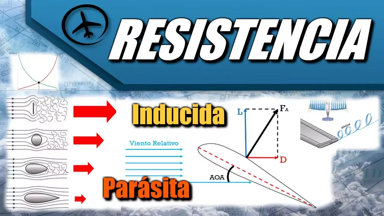
Resistencia - Aerodinámica
173.9K
Vortex drag is the portion of induced drag produced by wingtip vortices. These vortices form at the tips of wings due to the pressure difference between the upper and lower surfaces of the wing. High-pressure air from below the wing seeks to flow upward to the low-pressure area above, but finds only a narrow path along the wingtip. This creates circular rotating air patterns called wingtip vortices. These vortices cause additional induced drag, particularly noticeable during slow flight conditions.
Click to watch →
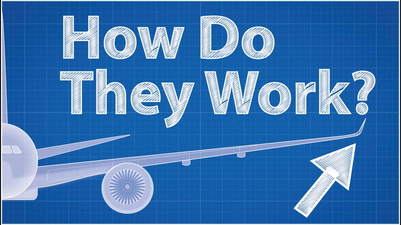
Winglets - How Do They Work? (Feat. Wendover Productions)
1.3M
Planes fly by creating high pressure air underneath their wings and low pressure air above. Fluids naturally flow from high pressure to low pressure regions, causing high pressure air from below the wing to bleed into the low pressure area above. This creates mini tornadoes (vortices) at the wing tips, which is called induced drag. This phenomenon decreases the lift of the wing and increases fuel consumption of the plane.
Click to watch →

induced drag and angle of attack| Lesson #3
8.1K
Induced drag is a type of aerodynamic drag that forms when the pressure difference between the top and bottom of a wing causes air to spiral inward at the wingtips, creating wingtip vortices; these vortices push down the airflow behind the wing (downwash), which tilts the lift vector backward and creates drag; this drag can be reduced by using longer, narrower wings (high aspect ratio) or by adding winglets that redirect airflow and minimize wingtip vortices.
Click to watch →

BIA Principes du vol 1 : Aérodynamique (2023-2024)
3.3K
Induced drag (traînée induite) is caused by the pressure difference between the upper and lower wing surfaces. High-pressure air below the wing flows around the wingtips to the low-pressure area above, creating wingtip vortices (tourbillons marginaux). These vortices represent energy loss and are a major source of drag, especially at high angles of incidence. The instructor explains that heavier aircraft produce stronger vortices because they require more lift, creating larger pressure differences. This is why small aircraft must maintain safe distances behind large aircraft during takeoff and landing.
Click to watch →
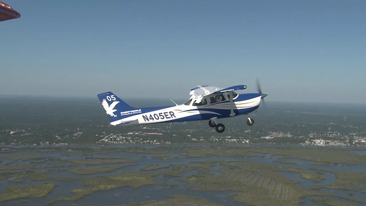
Principles of Flight: Aerodynamics Explained for Pilots
784.5K
Induced drag occurs because the wing creates downwash behind it, and wingtip vortices spiral from below to above the wing. These vortices tilt the lift vector backward, converting some vertical lift into rearward force. Induced drag is higher at slower airspeeds and decreases with increasing speed. It is worse at high angles of attack typical of slow flight.
Click to watch →
Deep Dive
The design and physics of high-lift devices, such as flaps, slats, and spoilers used in real-world aviation.
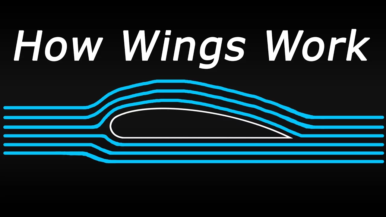
How Wings ACTUALLY Create Lift!
540.7K
This segment covers the three main types of high-lift devices used on aircraft wings. Flaps are located on the trailing edge and increase wing surface area and curvature, allowing slower takeoffs and landings but creating significant drag. Slotted flaps have gaps that allow air from underneath to flow over the flap, maintaining attached airflow at higher angles of attack. Leading edge slats extend forward from the wing's front, increasing surface area and incorporating slots for similar airflow benefits. Spoilers are flat panels on the upper wing surface that reduce lift by disrupting airflow, primarily used during landing to prevent re-liftoff and assist with deceleration. Fully extended spoilers cause turbulence, vibration, and noise discomfort for passengers.
Click to watch →
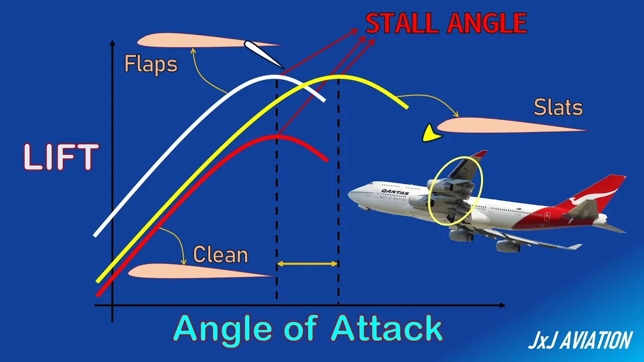
What are High Lift Devices? | Impact of High Lift Devices on an Aircraft Operation | Flaps & Slats
40.9K
High lift devices (flaps and slats) are wing-mounted surfaces that increase lift at low speeds during takeoff and landing; flaps extend from the trailing edge to increase surface area and camber, while slats extend from the leading edge to create slots that delay airflow separation; flaps primarily increase lift without changing the stall angle, whereas slats increase both lift and the maximum achievable angle of attack before stall, allowing safe low-speed flight operations.
Click to watch →

Superfícies da Aeronave - Aula 6 CGA
31K
Aircraft use multiple devices for high-lift and speed control. Flaps are the only combined lift augmentation and aerodynamic brake, located on wing trailing edges near the root. Types include simple, slotted, split, and Fowler flaps (most common in commercial aircraft). Slots and slats are pure lift augmentation devices on wing leading edges, creating openings that accelerate airflow to maintain lift at high angles of attack. Spoilers are aerodynamic brakes that disrupt airflow to reduce lift and increase drag, commonly used with flaps during approach and landing.
Click to watch →
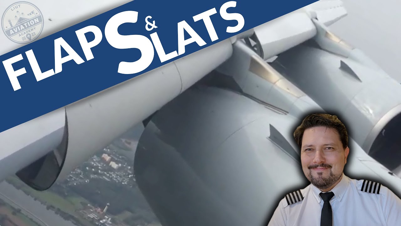
O que são FLAPS e SLATS? A asa “abrindo” no pouso e decolagem!
67K
Flaps and slats are high-lift devices on aircraft wings that enable safe flight at low speeds during takeoff and landing. Flaps, located on the trailing edge, extend backward and downward to increase wing curvature and surface area, generating more lift and drag. Slats, located on the leading edge, create channels that allow high-pressure air from beneath the wing to flow over the top, delaying airflow separation and allowing the wing to operate at higher angles of attack without stalling. These devices are retracted during cruise to reduce drag and improve fuel efficiency.
Click to watch →

High Lift Devices - Flaps
9K
Aircraft flaps are high-lift devices that increase wing lift during takeoff and landing by modifying airflow; they range from simple plain flaps that drop below the wing to create increased angle of attack, through split flaps that deflect from the lower surface with greater lift but more drag, to sophisticated slotted and Fowler flaps that create slots allowing high-pressure air to flow upward and delay flow separation, with triple-slotted flaps providing the maximum lift generation for large commercial aircraft like the Boeing 747.
Click to watch →
Deep Dive
Supersonic aerodynamics and how shockwaves alter lift generation at transonic and supersonic speeds.
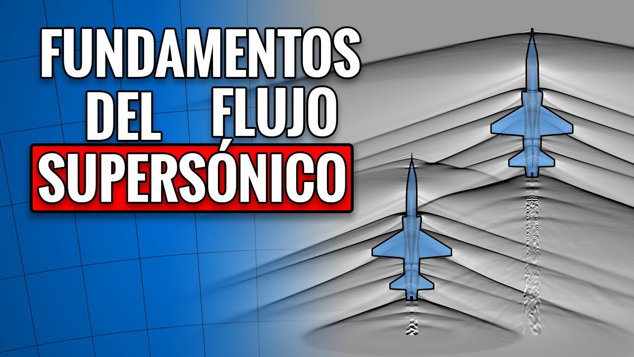
FUNDAMENTOS del FLUJO SUPERSÓNICO
18.5K
Supersonic lift generation differs from subsonic mechanisms. Even symmetric airfoils can generate lift at supersonic speeds when they have an angle of attack, with the lower surface generating higher pressure (compression) and the upper surface generating lower pressure (expansion). Shock waves cannot be avoided at supersonic speeds - they are an inevitable consequence of the physics. The presenter addresses biplane configurations, explaining that shock waves between wings don't contribute to lift because pressure increases cancel out. Swept wings delay shock wave formation by changing the effective angle of attack, allowing higher Mach numbers without drag divergence.
Click to watch →

High Speed Flight Part 1
90.5K
When an aircraft exceeds its critical Mach number, shock waves form on the wing—a sudden jump in air pressure across a very narrow region (about 1/10,000th of an inch thick) where supersonic air flow is violently reduced to subsonic speed. As the aircraft accelerates, the area of supersonic flow increases and the shock wave moves back along the wing, growing larger and stronger. Shock waves cause wave drag, a large proportion of total drag at transonic speeds, and shock-induced separation where airflow separates from the wing's surface, reducing lift and creating turbulence. Two chief design methods raise the critical Mach number: using thin wings (where maximum thickness is small compared to width or chord) and sweep back, which reduces the component of airflow that flows across the wing section. Sweep back to 35° can theoretically raise the critical Mach number from 0.8 to 0.98.
Click to watch →
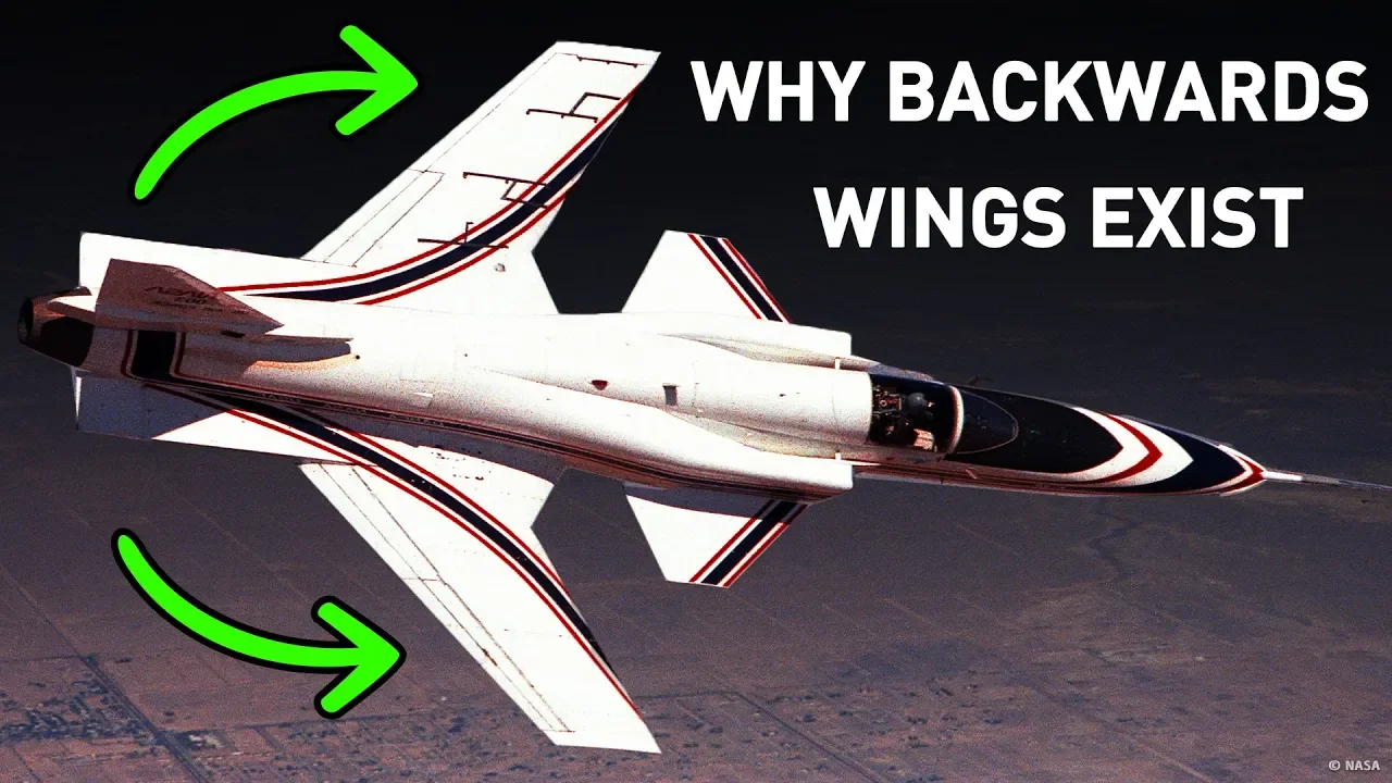
Why Some Planes Need Backwards Wings But Others Don't
179.5K
Aircraft wings are shaped to create higher air pressure on the underside than above, which generates lift. As aircraft accelerate, the air moving across the top of the wings moves faster than the plane itself. When an aircraft reaches speeds where the wing's top surface breaks the sound barrier (even if the aircraft as a whole hasn't), it creates a shockwave that disturbs the air behind it. This shockwave reduces lift from the forward wings while increasing lift from the rear wings, forcing the plane's nose down and causing it to lose altitude and gain additional speed.
Click to watch →

Kerbal Space Program - Interstellar Quest - Episode 28 - RAPIER Engines
329.8K
Aircraft aerodynamics change dramatically near and above Mach 1 (the speed of sound). At transonic speeds, shock waves form on wings, causing unpredictable changes in lift and drag characteristics. Supersonic flight (Mach 4+) produces entirely different aerodynamic behaviors compared to subsonic conditions. Aircraft designed for subsonic flight often exhibit poor stability and control at supersonic speeds without special design considerations.
Click to watch →
СУПЕРДЖЕТ - Анатомия региональника | аэродинамика и компоновка. Часть 2.
38.6K
At transonic speeds, localized supersonic flow zones develop on the upper wing surface, closing with shock waves that generate wave drag. Classical speed profiles used on aircraft like the Tu-154 featured high-intensity, unstable shock waves. Supercritical profiles solve this through flatter upper surfaces that create longer, weaker shock waves. The key geometric parameters include relative thickness (maximum distance between upper and lower surfaces), maximum thickness position along chord, and camber (curvature of the mean camber line). Supercritical profiles enable either higher critical Mach numbers at similar thickness or increased thickness at similar Mach, improving economic efficiency by 20-30% compared to previous generations.
Click to watch →
Wing Lift Myths
Unified Truth
Wing Lift Myths
0:00- 1
Common Bernoulli-based explanation is flawed and incomplete.
- 2
Air streams do not rejoin at the trailing edge, breaking key assumption.
Circulation Theory and the Limitations of Simplified Lift Models
While introductory physics often pits Bernoulli's principle against Newton's laws of motion (air deflection) to explain lift, aerodynamicists argue that both explanations are qualitative simplifications that fail to capture the complete picture. The counterpoint to these simplified models is the Circulation Theory of Lift, formulated via the Kutta-Joukowski theorem. This mathematical framework explains that lift is generated by 'circulation'—a theoretical vortex-like flow superimposed on the fluid stream around the airfoil. Critics of purely Newtonian or Bernoullian explanations argue that they cannot account for why the air curves along the airfoil's upper surface without incorporating fluid viscosity, boundary layer behavior, and the 'Kutta condition' at the trailing edge. From this perspective, trying to explain lift using only simple force deflection or pressure differences oversimplifies the complex fluid dynamics, and only computational fluid dynamics (CFD) and circulation theory provide a mathematically rigorous explanation.
Newton's Laws of Motion, particularly the Third Law (action and reaction) regarding force pairs.
Basic fluid dynamics concepts, including pressure, velocity, and how fluids flow around objects.
Bernoulli's Principle and its traditional (though often oversimplified) application to aerodynamics.
The concept of vector forces, specifically distinguishing between lift, drag, thrust, and gravity.
The Coandă Effect and its role in keeping airflow adhered to the curved upper surface of a wing.
The relationship between the Angle of Attack (AoA) and aerodynamic stall conditions.
Induced drag and the formation of wingtip vortices caused by pressure equalization.
The design and physics of high-lift devices, such as flaps, slats, and spoilers used in real-world aviation.
Supersonic aerodynamics and how shockwaves alter lift generation at transonic and supersonic speeds.
1.6M views24.1Klikes2:50@veritasiumOriginal Release: 2012-08-03
Shh... I've snuck into minutephysics' studio to explain how a wing actually works Hang on, something doesn't feel right.
Ah, that's better.
Now everyone knows that a wing generates lift due to its characteristic shape Since air travels farther over top of the wing, it must go faster than the air underneath so that both streams meet up simultaneously at the trailing edge And according to Bernoulli's principle, faster flowing air exerts less pressure than the slower air beneath the wing This pressure difference creates an upward force -- lift.
Job done.
Right?
Nope This simple explanation taught in many textbooks and classrooms has obvious problems Like how could a plane fly upside down?
Some planes like the Wright brothers' had nearly flat wings.
So presumably air would travel the same speed over both sides and there would be no lift Plus experiments show that air streams don't meet up at the back of the wing.
Air over the top goes significantly faster, reaching the trailing edge first.
So how does a wing actually generate lift?
Well the key is the wing must deflect air downwards This can be achieved using asymmetric or cambered air foils Or by increasing the angle of attack Air under the wing is deflected down And by the coanda effect air above the wing is guided along its surface and down as well Since the air is slowed and deflected down by the wing, it pushes the wing up and back.
Lift, and drag.
This is in accordance with Newton's Third Law of Motion But hang on, if you can explain lift only using the deflection of air and Newton's laws, then the Bernoulli explanation must be completely wrong Well, no, air over the top of the wing does go faster than air beneath, creating a pressure difference that generates lift Then this Newtonian explanation is unnecessary rubbish and the original explanation was right!
That's not true either.
The original explanation incorrectly assumed that air over and under the wing must reconnect at the trailing edge, and there was no mention of deflecting air down.
Each explanation, done correctly, completely accounts for the lift generated by a wing.
They're just two different ways of looking at the same thing.
So next time someone brings up the standard misconception, you can tell them that explanation just doesn't fly.
And if you liked that, you've gotta check out MinutePhysics.
I've got total respect for a guy who does this every week.
Sincerely, a collection of particles known as Derek.
Up Next

72:07
Airplane Aerodynamics Lecture | Private Pilot Ground School
@mitocw
3.6M views•2020-04-27

30:32
Ultrasonic Transducers: Resonant Frequency Measurement and Horn Design
@imajeenyus42
229.9K views•2017-02-22

33:39
How a Student's Question Saved a NYC Skyscraper from Collapse
@veritasium
22.8M views•2025-04-26
55:00
The Advanced Engineering Behind ASML's EUV Lithography Machines
@veritasium
18.2M views•2025-12-31
Related Study Plans & Knowledge Roadmaps
Structured learning paths in Engineering
engineering
Building Acoustic Levitators: Physics & Arduino
01The Physics of Sound and Standing Waves
02Piezoelectric Transducers and H-Bridge Drivers
03Arduino Programming: Generating 40 kHz Signals
+ 2 more learning modules
14h5 modules
Explore Roadmap
engineering
Building Peltier Cloud Chambers: Particle Tracks
01Cosmic Rays & Cloud Chamber Physics
02Thermoelectric Cooling (TEC) Fundamentals
03Custom Liquid-Cooling Loop Design
+ 2 more learning modules
18h5 modules
Explore Roadmap
engineering
Yagi-Uda Antennas: Modeling, Build & VNA Test
01Introduction to RF and Antenna Fundamentals
02Yagi-Uda Antenna Design Principles
03Antenna Modeling and Simulation in 4NEC2
+ 2 more learning modules
18h5 modules
Explore Roadmap
engineering
ECG Monitor Design: Op-Amps, Filters & Noise
01Electronics & Breadboard Basics
02Op-Amps and Instrumentation Amplifiers
03Bioelectricity and ECG Fundamentals
+ 2 more learning modules
18h5 modules
Explore Roadmap