



![26년 완자 생명 p200~p202 [혈액의 응집반응]#항원항체반응#혈액형](https://i.ytimg.com/vi/sy1QzXlCjSc/sddefault.jpg)













![[CSE031] Computing - Lec. (8) - Dr. Hassan Shehata - Fall 2020](https://i.ytimg.com/vi/hqxGQcIJyuI/sddefault.jpg?sqp=-oaymwEmCIAFEOAD8quKqQMa8AEB-AGEB4AC0AWKAgwIABABGGUgWyhcMA8=&rs=AOn4CLCI6z1uuUiGpD1vtM7sieTeKNBu6Q)








Biosensors are self-contained analytical devices that convert biological responses into electrical signals through five key components: a biochemical recognition element, transducer, amplification, signal processor, and display; three primary types include amperometric biosensors (measuring electron exchange proportional to analyte concentration), optical biosensors (using light absorption governed by the Beer-Lambert law), and potentiometric biosensors (following the Nernst equation for electrolyte measurement); microfluidics involves manipulating fluids at submillimeter scales, with fabrication methods including photolithography, embossing, and injection molding, and flow behavior governed by Poiseuille's law where flow rate is proportional to the fourth power of channel radius, making laminar flow dominant and mixing primarily diffusion-limited.
Biosensor Principles & Microfluidics in Point-of-Care Testing
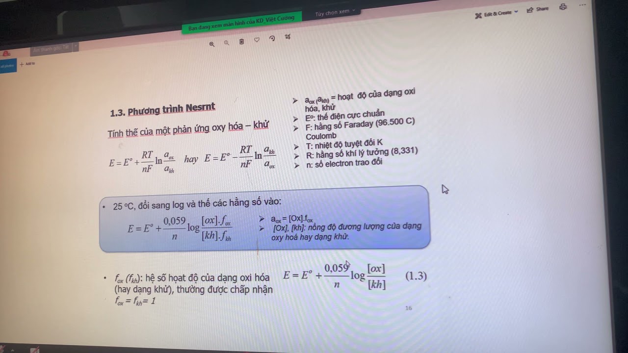
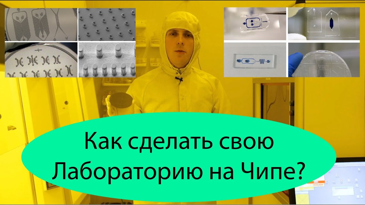
Added:biosensor principles and microfluidics this lecture is meant to give a brief overview of biosensor design principles as well as introduce biosensors commonly used in point of care testing this is followed by an introduction into the design considerations surrounding microfluidics including fabrication fluid transport Valves and mixing my name is Keith Brock this lecture is brought to you by the University of California Davis Lauren Livermore National laboratory's point of care Technology Center the UC Davis llnl point of care Technology Center has no financial interest in any of the companies represented in this educational tool the information contained in this training video is educational and intended for informational purposes only always consult the vendor approved instruction manual prior to performing any point of care test the international unit of pure and applied chemistry defines a biosensor as a self-contained integrated device which is capable of providing specific quantitative or semi-quantitative analytical information using a biological recognition element which is in direct spatial contact with a transducer element or simply put a biosensor is any analytical device which converts a biological response into an electrical signal typical biological responses may include hormones electrolytes neurological signals or enzymes this slide illustrates the generic elements of a biosensor number one the biochemical recognition element often this will include a selectively permeable membrane number two is the transducer element which converts the biochemical event to an electrical signal most common biosensor transducers include electrochemical and Optical transducers which we will discuss in detail later in this lecture less common biosensor transducers include p Electric Thermo or magnetic transducers element number three is amplification wherein your biosensor will increase the power of the signal using an external power supply element number four is signal processor where your biosensor will filter and interpret the electrical signal into a clinically meaningful value element number five is the display wherein your biosensor will project this value as a digital readout all measurement signals are corrupted by noise noise is defined as unwanted signals introduced to the system by outside sources for example power lines radio or television electromagnetic waves filters are used to reduce noise and maximize the signal to noise ratio once the signal to noise ratio is optimized the biosensor output can be normalized with respect to the noise of the system system the resulting normalized data focuses on the biological response of Interest the biosensor transfer function is a mathematical model that defines the relationship between the output projected on the display and the input electrical signal developed by the transducer of a linear system the dynamic range of a biosensor refers to the range of input signal amplitudes over which an electronic device will operate within a set of specific parameters the signal resolution refers to the finest of detail in the measurement for continuous systems the signal resolution defines the minimum increment that can be discerned while there are many types of biosensors both on the market or in development for the purposes of this lecture we will focus on three amperometric biosensors Optical bio sensors and potentiometric biosensors are the most commonly used in point of care testing point of care Tes testing is defined as testing at or near the site of patient care Dr Leland Clark is credited with the invention of the First biosensor on his closet shelf in October of 1954 Dr Clark created the oxygen electrode 10 years later Dr Clark used the same glucose oxidized enzyme and reversed the polarity of the Platinum electrode to create the first amperometric glucose bio sensor since then recent Market projections expect the glucose monitoring Vias industry to exceed $18 billion in 2015 simply put the governing principle of amperometry is as follows when provided with a constant driving potential the analyte bound to the receptor will undergo an oxidation reaction that can be Quantified by measuring the electron exchange from the working electrode or the anode to the counter electrode or the cathode this electron exchange or current is limited by the diffusion of the analyte through a selectively permeable membrane and various boundary layer phenomena but in a well-designed test strip will be linearly proportional to the concentration of Target analyte amperometry is most commonly and famously found in glucose monitoring systems this figure illustrates the chemical reactions involving glucose dehydrogenase and ultimate generation of electrons to generate the current which is measured by the glucose meter here we have Illustrated a glucose and lactate Tri layer biosensor the outer membrane prevents large objects such as red blood cells and proteins from entering the sensor while allowing glucose or lactate to enter and react with the enzyme layer the enzyme layer generates hydrogen peroxide which diffuses through the inner membrane and interacts with the Platinum anode to yield electrons optically based biosensors use the difference in wavelength angle of refraction phase change or percent transmission between the initial incident light and reflected light to measure a Target analyte though outside the scope of this lecture our Center Partners at the Center for biophotonic Science and Technology specialize in the research development and application of new Optical tools and Technologies applied in medicine and the life sciences pulse oxymetry functions by measuring the difference in the visible and near infrared absorbance of fully oxygenated and deoxy ated blood because of its continuous non-invasive and instantaneous measurement of blood oxygenation pulo symmetry is currently used extensively in hospital settings another example of an optically based biosensor is the hemoglobin meter this biosensor functions using Target specific enzyme coupled to a d the color change measured by light absorption is proportional to the concentration of the target in the case of the hemoglobin meter rapid diagnosis of anemia both in routine patient care or urgent or emergency department settings can be accomplished in seconds Target specific enzymes coupled to a chemical die is Illustrated on the lower right hand corner as the reaction proceeds there is a color change relative to the concentration of the target found in the sample the color intensity is measured by a photometric method wherein the difference in transmitted wavelength is calculated and inter interpreted the beer Lambert law also governs the principle by which blood oxygenation is measured by pulse oxymetry Illustrated on the right according to the Beer Lambert equation the absorption of light is proportional to the path length L the concentration of absorbing species in the material C and the molar absorptivity Epsilon now we will see if we can apply the beer Lambert equation in an example problem given the total absorbance through the glass Channel or a total the absorptivity of the glass Epsilon glass and the concentration of absorbing substances in the glass c glass calculate the concentration of absorbing species in the sample buffer solution flowing through the glass Channel first calculate the absorptivity of the glass the absorptivity constant is given to be 2 L per M CM times the path length through a single layer of glass or.25 CM times the concentration of absorbing species of glass or one multiply this answer by two since the path of light goes through two layers of glass the glass component of the total absorptivity is found to be one next solve for the sample plus buffer component of the total absorptivity the sample plus buffer component of the total absorptivity is found to be nine solve the beer Lambert equation for the concentration of absorbing substances and plug in the absorptivity constant for our sample plus buffer solution and the path length through the sample plus buffer the concentration of absorbing species in the buffer plus sample solution is found to be 6 moles per liter potentiometric biosensors are used extensively in clinical chemistry specifically when measuring electrolytes these biosensors simply measure an electrical potential difference between two electrodes here Dr Yang at all have recently characterized potentiometric amperometric and Optical biosensors embedded in the elastic waist of underwear under tight direct contact with skin in this paper the textile based carbon electrodes have been shown to accurately measure hydrogen peroxide di potassium salt and ferrocyanide the potentiometric bio sensor simply measures an electrical potential difference between two electrodes these electrodes consist of a transducer and a reference that are connected electrically through the sample in a potentiometric circuit that behaves according to the nerst equation the nerst equation shows that the potential difference or Von is proportional to the boltzman constant temperature the charge of the ion and the natural log of the ion concentration gradient for measuring electrolytes such as sodium potassium calcium or chloride ion selective electrodes are used the Clark electrod tests for partial pressure of oxygen the current generated is proportional to the partial pressure of oxygen diffusing to the electrodes once again let's try to apply what we have learned the relative concentration of sodium ions both inside B and outside a the membrane are 50 Millar and 46 Millar respectively using the nurst equation solve for the electrode potential in molts note that K * t equal 61 molts to solve for the sodium ion potential across the membrane plug in 61 for the boltzman constant times the temperature then plug in the charge associated with the sodium ion or positive 1 always be sure to incorporate the of the ion in question next plug in the concentration gradient of sodium the sodium ion potential across the membrane is found to be 134.4 molts microfluidic is the study of the behavior control and manipulation of fluids on a submillimeter scale the 1949 inkjet patent described a method by which micro volumes of ink could be selectively deposited on paper today the application of microfluidic is used to create fully integrated devices performing several laboratory functions on a single chip only a few centermeters in size the miniaturization of diagnostic Technologies has been driven by the high cost of purchasing and maintaining fully equipped laboratory-based instruments historically the high costs associated with personnel and reagents the impracticality of instrument support and the physical distance between the test and patient have driven up the cost per test consequently the purchasing of new laboratory equipment has been largely based on the projected volume of testing replacing fiscal decision criteria with needs-based or impact-based criteria miniaturized diagnostic laboratories show promise to be cost effective through low initial and reagent costs and versatile consuming little to no energy resulting in affordable lowcost diagnostic testing this of course can have profound implications on otherwise underserved patient populations microfabrication of miniaturized diagnostic test has been heavily influenced by the semiconductor and micro electromechanical Industries common microfluidic fabrication methods include photolithography embossing and injection molding the fabrication method is determined by the material of choice the cost and speed of fabrication and the design specification photolithography or light printing is the process by which thin silicon Wafers are patterned using a photoactive polymer also known as photoresist polymethylsiloxane or pdms molds can be replicated using this silicon Master using this well established method one mask can make hundreds of Wafers and one wafer can make multiple molds with tolerance is limited by the wavelength of light one disadvantage of photolithography is the envir in which the mask must be created defects or dirt on the mask will ultimately transfer the defect to your designed wafer this slide illustrates the steps involved in photolithography first the metal coated silicon wafer is spin coated with photo resist once exposed to the light the light sensitive photo resist is degraded according to the shapes projected by The Mask through a process of wet or dry etching the metal layer is shaped to ref reflect the geometries made by the photo resist embossing is a technique that uses heat and pressure to shape thermop plastic materials against a master or a stamp pattern with access to a hydraulic press the advantages of embossing are that it is relatively cheap and fast though the fabrication of the stamp may be expensive in time consuming injection molding is a practice commonly used in the Plastics industry here pellets of thermoplastic are melted and injected under high pressure into heated mold cavities once cooled the newly formed part is released from the mold advantages of injection molding are excellent contact with features of the mold and higher throughput than embossing consequences of injection molding include the quality of the replica depends on the quality of the master and that it's not ideal for prototyping basic components of microfic devices covered in this lecture include pumps valves and mix of which there have been many types described in many Publications these components are combined to build application specific microfluidic systems for pressure-driven microfluidic systems such as those using syringe or vacuum pumps the pressure differential necessary becomes much higher at a microfluidic scale the flow rate Q is proportional to the pressure differential Delta p and the radius of the channel to the fourth power so for a tube diameter decrease by a factor of 100 such as 1 cm to 100 microm the change in pressure necessary to maintain the same flow rate must increase by a factor of 10 to the e8th in contrast electroosmotic flow is based on the movement of the bulk solution and response to the movement of counter ions near the surface of the channel walls in the direction of of an electric field advantages of electroosmotic flow include its distinct flat flow profile minimizing dispersion one example of activ gating microfluidic valves involves the layering of two polymethyl siloxane or pdms layers on a planer glass substrate the top layer houses the pneumatic controls while the bottom layer houses the fluidic channels one can easily see how pumps and mixers can be created using a series of similar pneumatically controlled configurations passive gating can be achieved using capillary burst valves in this example fluid driven by centrifical force is controlled by a a sudden expansion in the microfic channel B A hydrophobic coating on the channel wall both where the rotational speed must exceed the burst frequency for fluid to continue or c a hydrophilic u-shaped siphon Channel where the rotational speed must exceed the burst frequency for fluid to stop in order to better understand microfluidic mixing a brief overview of laminar and turbulent flow may be helpful a Reynolds number less than 2,130 will ideally result in laminer flow while a Reynolds number greater than 4,000 ideally results in turbulent flow fluidic mixing is most quickly and efficiently achieved in turbulent flow systems Reynold's number is calculated by multiplying the density of the fluid the average velocity of the fluid fluid in the direction of the flow and the diameter of the channel divided by the viscosity of the fluid so as the diameter of the channel becomes smaller so must the Reynolds number typical Reynolds numbers in microfluidic systems are less than one making microfluidic mixing difficult microfluidic mixing is typically limited by diffusion or the spread of particles through random motion from regions of higher concentration to regions of lower concentration diffusion can be modeled using using the top equation where X is the diffusion distance D is the diffusivity constant and T is time to speed diffusion mixing researchers have developed unique three-dimensional Serpentine microchannels to encourage chaotic advection today multiple types of micro pumps mixers and micro valves have been developed by thousands of researchers with little to no standards defined for interc connectability it is no longer enough to design an elegant microfluidic component the future of microfluidics is a platform that provides easy combination of reliable components universally integrated using well-defined lowcost fabrication technology researchers are now moving their focus towards the application of microfluidic systems that incorporate strategic biosensors to address high impact clinical needs
Up Next
Aptamers in Therapeutics and Diagnostics | Oligonucleotide Applications
@BioResource
37.8K views•2014-05-13
Quantitative Real-Time PCR (qPCR): Principle, Method & Data Analysis
@animatedbiologywitharpan
129.2K views•2023-09-06

Microbial Degradation of Plastics: Biodegradation Pathways & Sustainability
@majeedhammad
2.9K views•2021-04-11

CRISPR and Genetic Engineering: How Gene Editing Works and Why It Matters
@kurzgesagt
30.5M views•2016-08-10
Related Study Plans & Knowledge Roadmaps
Structured learning paths in Biotechnology