














Electrical Rules Check (ERC) is a verification tool in KiCad that identifies common schematic errors before PCB layout, including pin conflicts (connecting power output pins together), unconnected pins (requiring no-connect flags), and undriven pins (requiring power flags); to run ERC, first annotate the schematic, then use the ERC tool to test and fix errors by double-clicking to locate issues and applying appropriate corrections.
KiCad Tutorial: Running Electrical Rule Check (ERC) on Schematics
Added:Basic navigation of the KiCad Schematic Editor, including placing components and drawing nets/wires.
Fundamental circuit concepts, particularly the distinction between different pin types such as Input, Output, Passive, and Power.
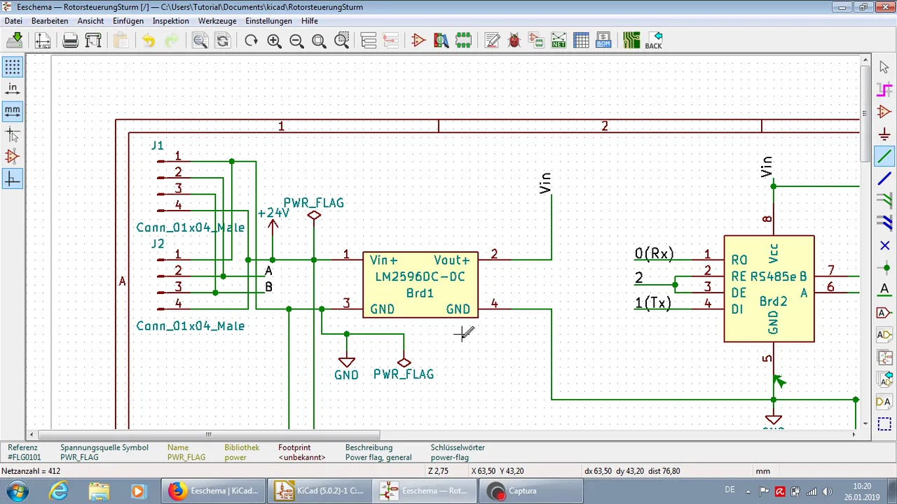
The purpose and concept of Power Flags (PWR_FLAG) in CAD software to designate where power is actively supplied to a net.
An overview of the electronic design workflow, recognizing why schematic validation is crucial before proceeding to physical PCB layout.
Transferring the verified schematic data to the KiCad PCB Layout Editor to begin footprint placement and routing.
Running Design Rule Checks (DRC) on the physical PCB layout to detect trace clearance, routing, and manufacturing violations.
Configuring custom ERC rules and editing the Pin Conflicts Matrix in KiCad to suit specific organizational or design-level constraints.
Handling complex connectivity and signal integrity in multi-sheet, hierarchical schematic designs.
9.7K views60likes7:33Original Release: 2013-06-18
[Music] Welcome to Nimato Labs Kikar tutorial part 7. In this video we will learn about running electrical row check or ERC on the schematic sheet and uh fix some of the errors that can pop up in your schematic.
It is highly recommended that you run ERC on your schematic and fix all the errors before you proceed to the next step that is PCB layout. I have a simple circuit here um that obviously do have some intentional mistakes uh so that we can run ERC and uh show you some of the most common errors and how to fix them. I have two LM317 load dropout voltage regulators um here and uh there's an external power supply and there's a battery here as well. The idea is that when external power supply is available um this LM317 will be active and uh the rest of the circuitry will be powered from external power and when external power is not available this LM317 will be active and the battery will power the rest of the circuit. So let's go ahead and uh run ERC. To run ERC, go to the main toolbar and select perform electrical rule check button and a window will pop up and uh there are two tabs in the window. The first one is ERC tab and the other one is options. We'll take a detailed look at this options tab um in one of the advanced videos that's going to come out very soon. So for now, we're going to leave all these options as is. go to the ERC tab and to run ERC click on the test ERC button on the top right corner. So I clicked the uh test ERC button then and uh it came up with the message saying that annotation required.
That is right. So before running the ERC you need to annotate the schematic. To annotate the schematic select the annotate schematic tool. Click on annotation button and close. Now the whole schematic is annotated. So let's go back to the ERC tool again. Um and try to run ERC once again. Click on test ERC button. And now the tool went through the whole schematic and came up with a list of errors that it found in the schematic. So there are three errors here. We'll take a look at these errors one by one and find out what are those errors and how to fix those errors. The first error is conflict problem between pins and the severity is error. That means it is pretty um severe stuff and you don't want to ignore this error.
What it says is pin three, that's a power out pin of component U2 is connected to pin 3 of component U1. What this error says is that you have connected two power out pins together and it is obvious that you don't want to tie two um power rails together and that's a big mistake. How do we find where exactly the error is?
This circuit is very simple. But when you have a very large circuit, it may not be easy to go look it up manually.
So to go to the exact location where the error is, double click on the error and uh the cursor will be moved to the exact location where the error is. Now you can see here there is a marker and the marker color is red that means a severe error. Pin number three of this LM317 and pin number three of this LM 317 are connected together. The next error is pin not connected. Okay, let's go find out where the pin is not connected. So as you can see here this particular pin of resistor R3 is not connected to any other net. To fix this problem there are two ways. If you did this by mistake, you can always connect to the uh correct uh net or if this is intentional, you can mark it as an unused pin. To mark this pin as an unused pin, go to the toolbar on the right and select place a no connect flag and left click on the pin to place the no connect flag. So now that we have um a no connect flag on this particular pin, let's go back to the ERC tool and run the ERC again. Run ERC again and that error disappeared. So the third error is pin connected to some others pins but no pin to drive it. pin one that is a power in pin of component power 01 is not driven. So um again double click on the error to go to the point where the error is. So this error looks like uh is on a ground um symbol.
So what is what this means is that um this net is connected to many other pins um but or this pin is connected to many other pins including here here and here but there is no power to drive this pin.
Okay. So if you go back and look at the error, you can see pin one is a power pin. So when you have a power in pin on a net, you have to have a power out pin as well. In this case, we don't have a power out pin in anywhere on the ground net.
So to fix this problem, what you can do is you can use a power flag. To place a power flag, go to the power uh port tool and left click and go to list all.
Scroll all the way down and select power flag. Click on the power flag. Click okay and place it somewhere near um the ground and wire the power flag to the ground.
Now we have this power flag that is connected to the ground and we can go back to the ERC tool and run ERC again. Just ERC and that error is disappeared. We have only one error left here. We can remove the error by disconnecting um these two points. Let's run ERC again. And that error is gone.
Thanks for watching. Stay tuned.
Up Next
12:16
KiCad 7 Tutorial: PCB Constraints, Net Classes & Directive Tool
@pcbcupid
68.9K views•2023-03-13

12:54
Triumph of Orthodoxy Icon: Byzantine Art & History Explained
@BenCallan
2.1K views•2024-08-06

9:49
FastAPI vs Flask vs Django: Choosing the Right Python Web Framework
@TechWithTim
302.5K views•2024-05-26

1:42
Game of Thrones Opening Credits: A Cinematic Analysis
@gameofthrones
46.3M views•2011-04-18
Related Study Plans & Knowledge Roadmaps
Structured learning paths in General & Interdisciplinary Studies
general-studies
Elevator Engineering: History, Physics & Cities
01From Hoists to Safety Brakes: The Dawn of Vertical Lift
02Hydraulic vs. Traction: The Engineering Physics of Elevators
03Modern Speed, Safety, and Algorithms
+ 2 more learning modules
12h5 modules
Explore Roadmap
general-studies
Rubber: Material Science, History & Geopolitics
01Origins of Natural Rubber & Mesoamerican History
02The Chemistry of Natural Rubber & Vulcanization
03The Geopolitics of the Rubber Boom & Colonization
+ 2 more learning modules
12h5 modules
Explore Roadmap
general-studies
Containerization: Evolution, Logistics & Trade
01Ancient Trade & Bulk Cargo: Amphorae to Barrels
02The Industrial Revolution & Cardboard Packaging
03The Containerization Revolution: Malcom McLean
+ 2 more learning modules
12h5 modules
Explore Roadmap
general-studies
Textile Tech: Evolution, Labor & Global Impact
01Pre-Industrial Textiles: Handloom & Cottage Industry
02Mechanization: The Spinning Jenny to the Power Loom
03The Factory System & Global Labor Transformation
+ 2 more learning modules
10h5 modules
Explore Roadmap