







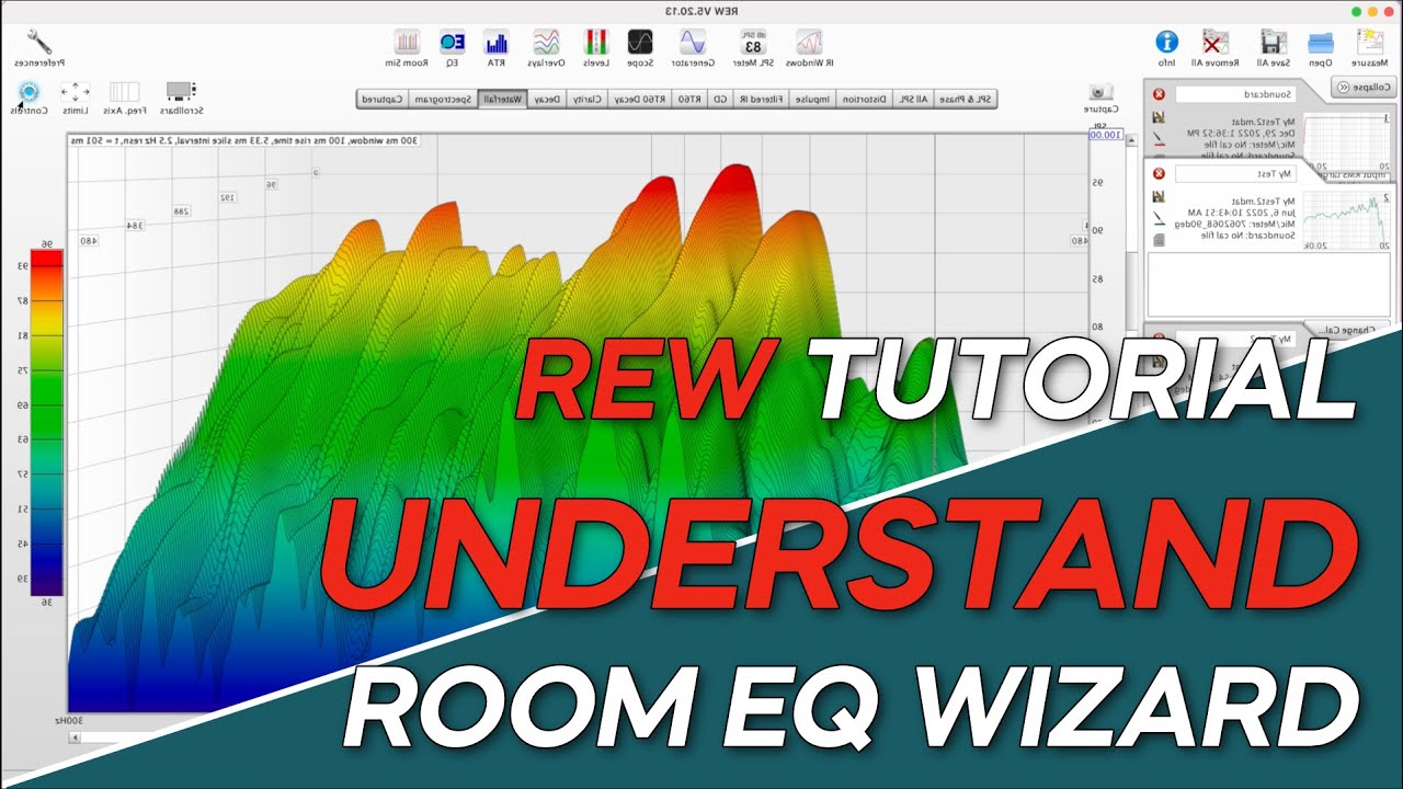
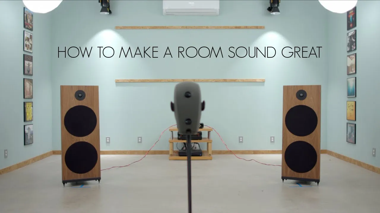
![[繁中字幕] REW 數據判讀: 頻率響應/相位/脈衝響應/RT60/瀑布圖/頻譜圖/重低音整合/SBIR/ETC](https://i.ytimg.com/vi_webp/Es-B3BLoLsQ/maxresdefault.webp)
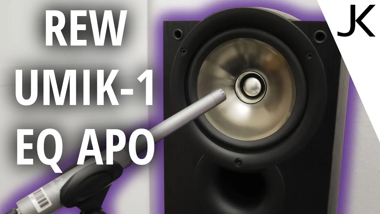
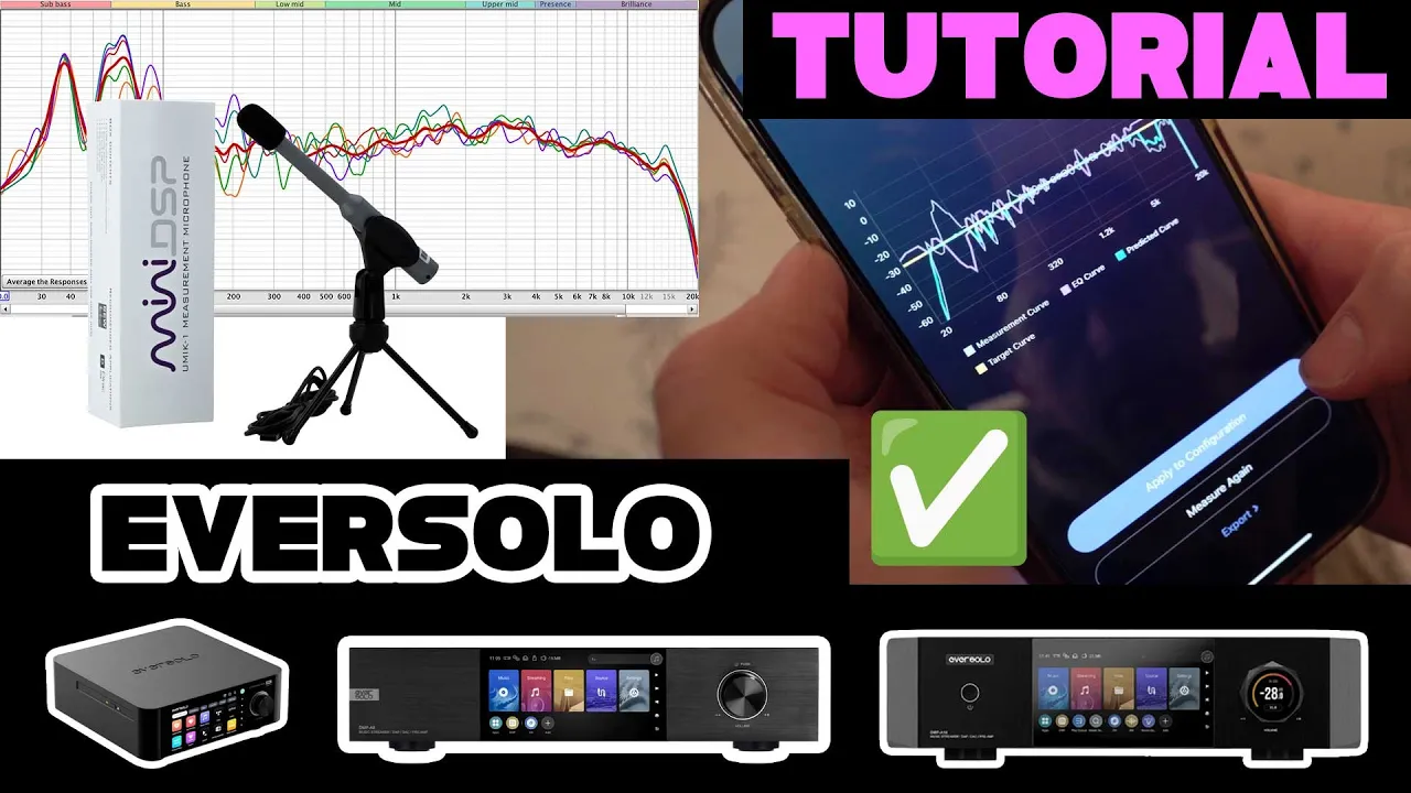
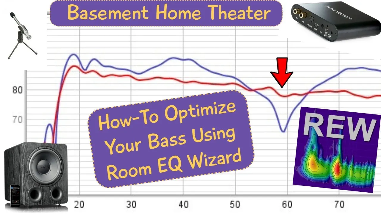






Transfer function measurements determine how an audio system responds to different frequencies by sending a frequency sweep through the system and comparing the output to a reference signal, allowing users to analyze the system's frequency response using free software like Room EQ Wizard; however, acoustical measurements face challenges from room acoustics, microphone frequency response, and speaker characteristics that can introduce errors, making it important to use equipment with flat frequency responses and understand the limitations of measurement environments.
How to Measure Frequency Response with Room EQ Wizard (REW)
Added:Fundamentals of acoustics, including frequency (Hz), amplitude (dB), phase, and how sound waves propagate and reflect in closed spaces.
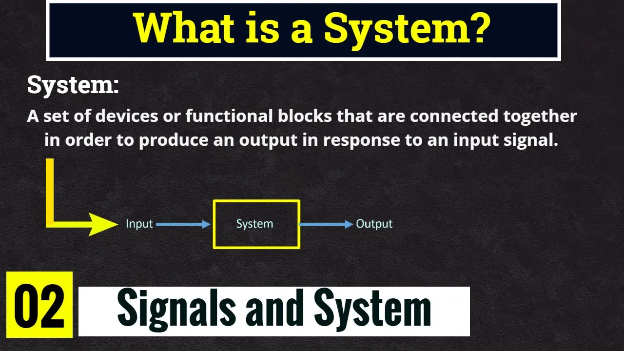
The mathematical concept of a transfer function, which defines the relationship between a system's input signal and its output signal.
Basic components of an audio measurement signal chain, including test signals (sweeps, pink noise), audio interfaces, and calibrated measurement microphones.
How to read and interpret a basic frequency response graph (amplitude versus frequency).
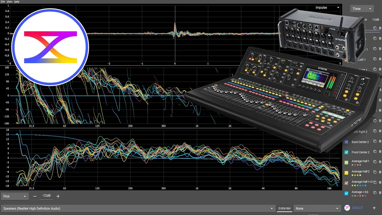
Analyzing advanced acoustic metrics in REW, such as Waterfall plots, Spectrograms, and Impulse Response to identify room decay times (RT60) and early reflections.
Exporting EQ correction curves from REW and applying them to hardware or software DSPs (such as MiniDSP or Equalizer APO) for active room correction.
Deploying targeted passive acoustic treatments (bass traps, absorbers, and diffusers) based on measured modal resonances and nulls.
Implementing multi-subwoofer integration and phase alignment techniques to optimize low-frequency coverage across multiple seating positions.
190.3K views3.9Klikes7:04Original Release: 2021-02-11
In a previous video, I talked about frequency response and what it tells us about an audio system. Click here to watch that video and learn what frequency response is and why it's important.
This video answers a slightly different question: "How is frequency response measured?".
I'll show you a basic technique and free software that you can use to measure the frequency response of your room, your speakers, your microphone, or any other audio system. But if this is our first time meeting, my name is Kyle. You can learn audio production online by checking out the weekly videos i post to the Audio University YouTube channel. Learn more at AudioUniversityOnline.com.
The method we'll use in this video to determine the frequency response of a system is called a transfer function measurement. A transfer function of a system is a mathematical function which models the system's output for each possible input. In this case, we'll be measuring how a system responds to various input frequencies. By sending each frequency equally to the system's input and measuring the signal again at the output of the system, we should in theory be able to determine the effect that the system has on the signal.
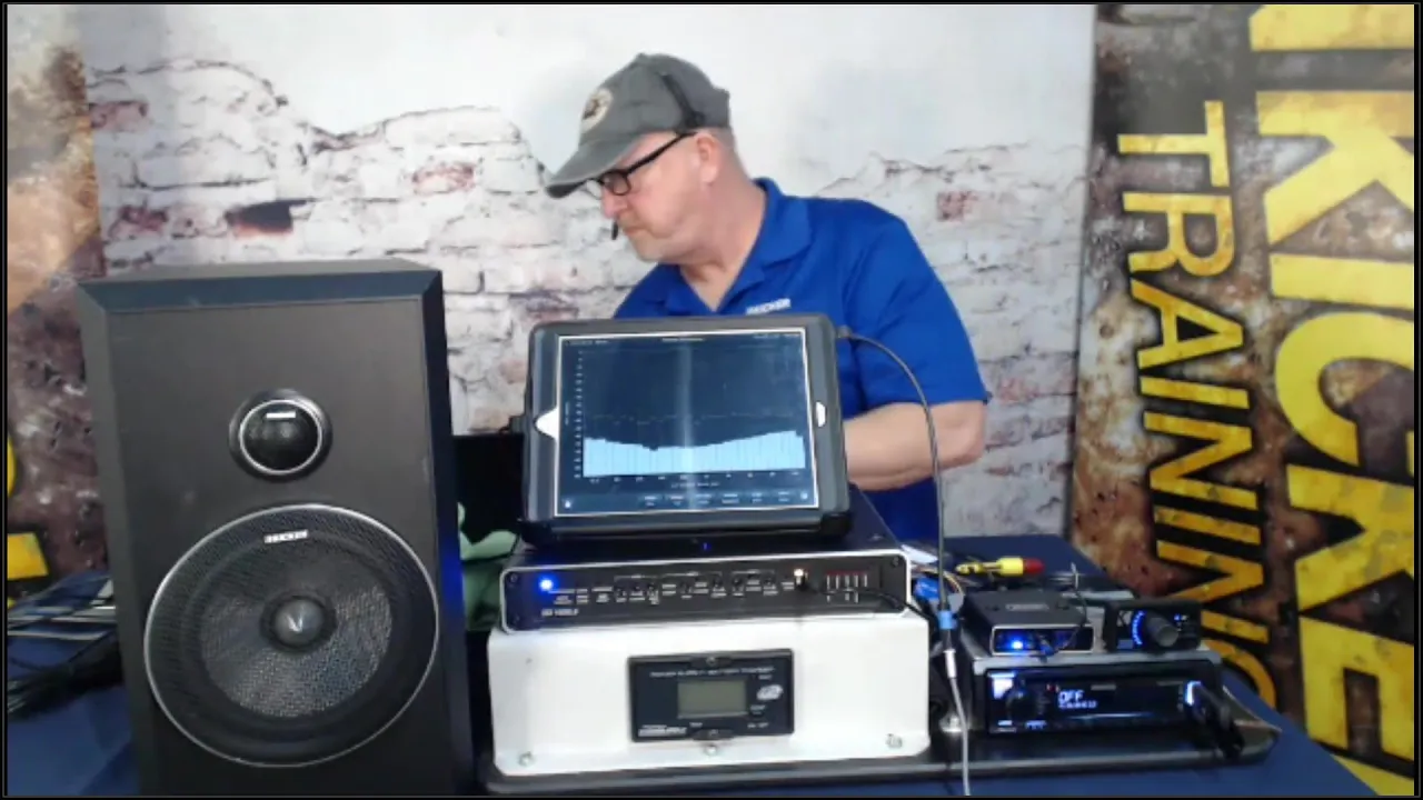
A basic setup for making acoustical measurements consists of a computer, a measurement software, an audio interface, a speaker, and a microphone. There's no need for a special computer. You can use whatever you currently have access to. In fact, there's even a free measurement software called Room EQ Wizard, or REW. I've put a link to the REW download page in the description below this video. You'll need an audio interface with at least one microphone input, one line input, and two line outputs. The speaker that you choose will depend on what you're measuring. If you're measuring the transfer function of a room or a microphone, you'll want to choose a speaker that has as close to a flat frequency response as possible so that it can create each frequency evenly, or at least have a speaker that you know the frequency response and can adjust your measurement accordingly. The same goes for the microphone. If you're measuring something other than the microphone itself, you should choose a mic that has a known frequency response or a microphone with a very flat frequency response.
Otherwise, the sound of the microphone will color the end measurement. Check out the list of tools that I use for acoustical measurements and tuning systems in the description of this video.
To set up a basic measurement, I'll start by opening Room EQ Wizard.
In the top left corner, click "Measure". This window will pop up. You can see that the software will test the audio system by sending a frequency sweep signal. This will test how the system responds to each frequency along that sweep. Let's set up the inputs and outputs. I want the test signal to play through Output 1 or the left output of my audio interface.
That's the output that I'll connect to the input of the system I'm testing.
I'll connect the output of the system I'm testing to Input 1 on my audio interface.
Select Input 1 as the input in the REW software. We'll also need to set up a path for a reference signal. In a basic test, this is simply a cable that connects Output 2 of the audio interface directly into Input 2 of the audio interface. This allows the software to ignore any effect that the output and input of the audio interface have on the signal, because both the test signal path and the reference signal path will include these elements. More on this later.
Before testing, it's important to check levels. The test signal will play out of the two outputs we've selected. The goal is to adjust the gain until the test input signal and the reference input signal are the same level. Once you've got the levels dialed in, click "Start Measuring".
After the test signal plays, you'll see the results of the test.
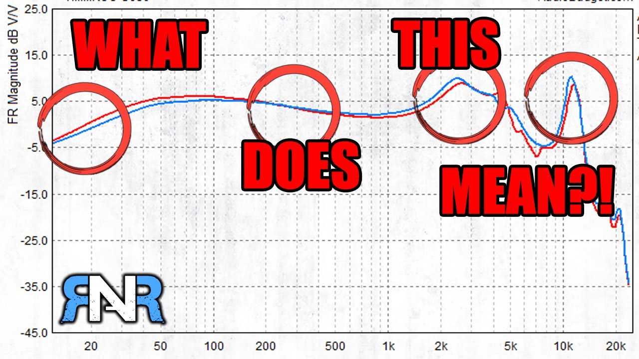
This graph should look familiar if you've watched my videos on frequency response graphs.
To learn how to interpret this graph, click the link in the top right corner of your screen.
Unfortunately, it's sometimes difficult to get accurate measurements - especially acoustical measurements. That's because there are so many variables at play that need to be accounted for.
To understand this better, let's take a look at a very simple electrical measurement.
In a basic measurement of an electronic device, it's much simpler. The test signal path includes the interface output, the electronic device (such as an equalizer), and the interface input.
The reference path only includes the interface output and the interface input.
This makes it possible for the software to measure only the changes caused by the electronic device.
However, consider all of the complexities that exist in an acoustical measurement that don't exist in an electrical measurement. Let's say I want to measure the transfer function of my speaker. The path of the test signal includes not only the speaker, but the room and the microphone too. The acoustic properties of the room could result in cancellations, resonances, and other anomalies that we have no way of accounting for in the reference signal. The microphone also has a frequency response of its own. If we know the frequency response of the mic we're using, we can adjust for it. But if we don't know the frequency response, it will affect the results of our test.
Luckily some of the most brilliant minds in the audio industry have come up with ingenious ways of overcoming these obstacles.
Many tests of speakers and microphones are done in anechoic chambers - spaces specially designed to eliminate reverberation, resonance, and echo. Acousticians, researchers, and system techs also use specially designed speakers and microphones that either have a very flat frequency response or a known frequency response that can be accounted for later.
Let's face it: most of us don't have access to laboratories or environments that are specifically made for acoustical measurements, let alone the expensive tools required to get the most accurate measurements possible. But that certainly doesn't mean that we wouldn't benefit from experimenting and trying to get good measurements on our own.
If you're a student of audio, you'll definitely benefit from going through this process.
Just the act of considering all the different components of your system and brainstorming ways to isolate the measurement to only measure a specific component is a great exercise. Do your best using the steps in this video to set up a measurement that helps you understand the effect a single component of your system has on the signals passing through it. If you don't have the tools required to measure only one component of your system, measure the system as a whole but consider the effects that each individual component will have on the results of that test.
Hit the "Like" button if you found this video helpful and subscribe to Audio University for more content like this.
Up Next

34:27
How to Analyze Acoustic Measurements in Room EQ Wizard
@MusicCityAcoustics
204K views•2022-04-30

30:32
Ultrasonic Transducers: Resonant Frequency Measurement and Horn Design
@imajeenyus42
229.9K views•2017-02-22

54:16
Polymer Environmental Degradation: Mechanisms & Stabilization
@iit
1.8K views•2012-07-10

33:39
How a Student's Question Saved a NYC Skyscraper from Collapse
@veritasium
22.8M views•2025-04-26
Related Study Plans & Knowledge Roadmaps
Structured learning paths in Engineering
engineering
Building Acoustic Levitators: Physics & Arduino
01The Physics of Sound and Standing Waves
02Piezoelectric Transducers and H-Bridge Drivers
03Arduino Programming: Generating 40 kHz Signals
+ 2 more learning modules
14h5 modules
Explore Roadmap
engineering
Building Peltier Cloud Chambers: Particle Tracks
01Cosmic Rays & Cloud Chamber Physics
02Thermoelectric Cooling (TEC) Fundamentals
03Custom Liquid-Cooling Loop Design
+ 2 more learning modules
18h5 modules
Explore Roadmap
engineering
Yagi-Uda Antennas: Modeling, Build & VNA Test
01Introduction to RF and Antenna Fundamentals
02Yagi-Uda Antenna Design Principles
03Antenna Modeling and Simulation in 4NEC2
+ 2 more learning modules
18h5 modules
Explore Roadmap
engineering
ECG Monitor Design: Op-Amps, Filters & Noise
01Electronics & Breadboard Basics
02Op-Amps and Instrumentation Amplifiers
03Bioelectricity and ECG Fundamentals
+ 2 more learning modules
18h5 modules
Explore Roadmap