





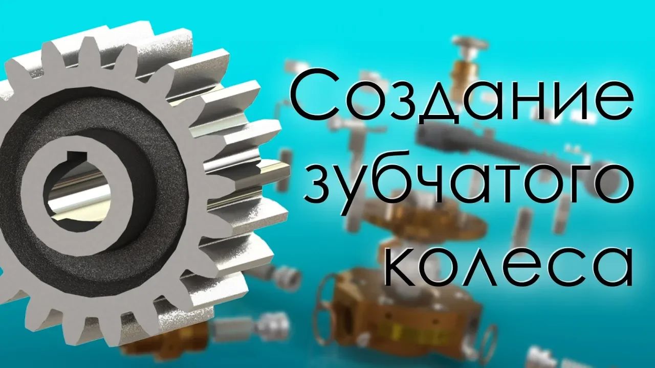







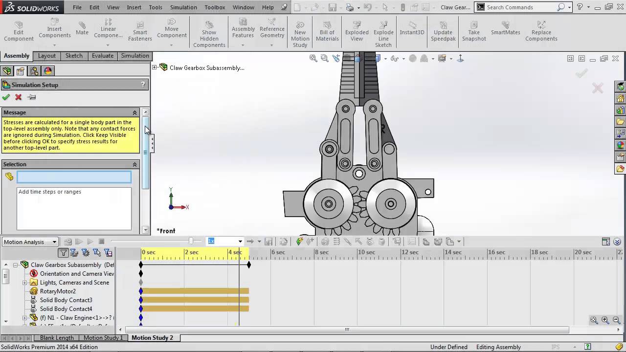
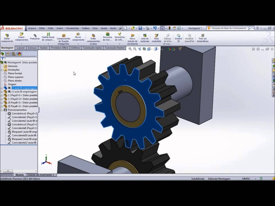
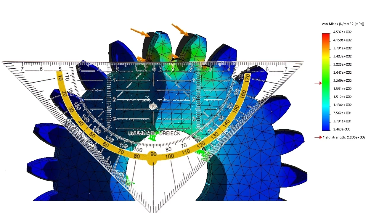
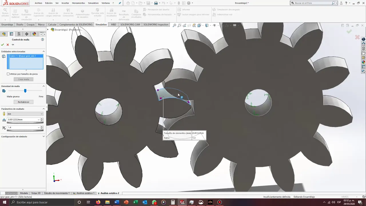



This video tutorial demonstrates how to create an involute spur gear in SolidWorks using equation-driven modeling, where key parameters like diametral pitch, pressure angle, addendum, dedendum, pitch diameter, and base circle diameter are defined through equations. The process involves sketching the addendum circle, creating reference circles (pitch, base, and dedendum circles), generating involute curves using parametric equations, applying angular constraints based on the number of teeth, trimming unnecessary geometry, adding fillets, and finally using circular pattern to replicate the tooth profile around the gear. The model can be easily updated by modifying the number of teeth or other parameters, making it suitable for course projects requiring customizable gear designs.
Equation-Driven Involute Spur Gear Modeling in SolidWorks
Added:Hello class. Uh this video is for tutorial number six ENGR 380. In this tutorial you will learn how to model a involute profile spurge gear using solid works. Here is the parameter used in this tutorial. Diametric page numbers and a pressure angle.
Uh I will mostly follow the procedure listed in the tutorial. uh but I'll slightly uh change that to a more advanced level. Basically, I'm going to use equation to drive the um drive the modeling of this uh gear.
Essentially, at the end, you can update the dimensional peach and number of teeth if you want a different gear.
Okay? So that you don't have to go through the process anymore. Okay? So you can actually probably use that in your project in the course project in the later part. Okay. So let's get started. So first to create a new part.
So first step is we're going to uh sketch a circle uh which is basically our addendum circle. The addendum circle uh is the uh outer edge.
So let's dimension this circle at here.
Okay. So just leave the circle as it is.
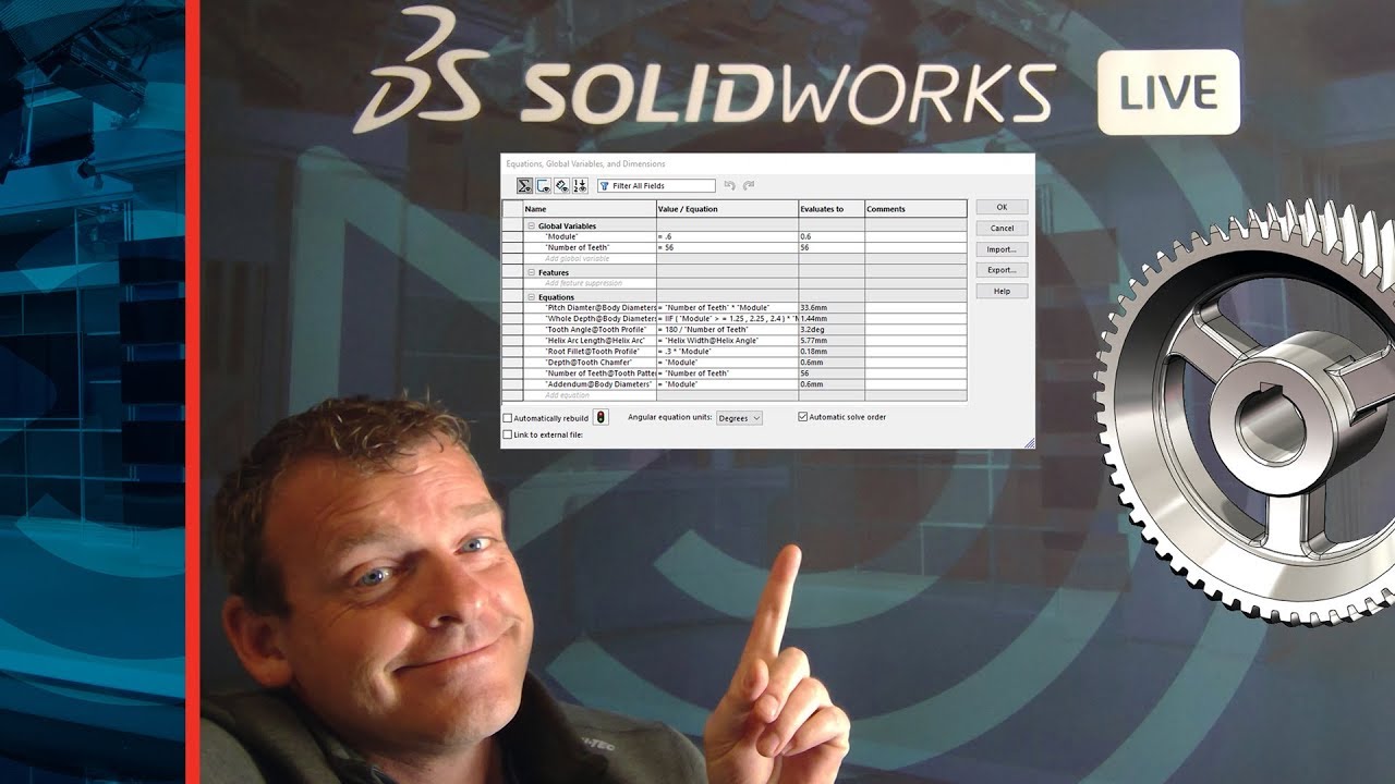
The radius uh there. Notice there's a d1 at sketch one. That's the radius of the dimension there. So, but we're going to uh change this drive that using equation. Okay. Yeah. So, go to tools and then equations.
So, here we're going to add a few things here. First down Metro Peach then number then uh pressure angle.
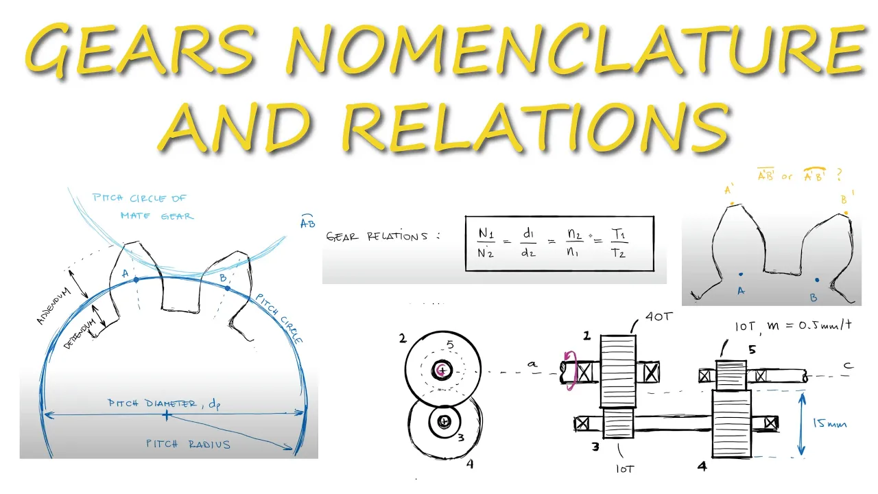
So the let's here choose sorry uh choose degree okay. So and then uh we will need a few more parameters as you as we as you recall in the lecture we learned uh we'll we'll enter this addendum dendum layer. Okay so addendum is the difference between the denim circle diameter and the pitch diameter. Dendum is the difference between the peach diameter peach circle diameter and the dendum circle diameter.
So that's a a is a dendum that's one over capital p then b is the dendum that's 1.25 over capital p.
So I need the clearance there. That's B minus A. That's clearance.
Okay. Yeah. Okay. So what else do we need? Uh we are also going to uh need this uh diame uh the pitch diameter DP. So pitch diameter DP is N over capital P.
So this is the pitch basically pitch circle diameter.
So and then the next one is a base circle diameter DB. DB is related to DP by cosine DP * cosine 5.
Okay. So that's space circle diameter.
Okay. So I guess well that's that's enough so far. And now go to this equation here. Click on the equation first. Okay. And then okay move your cursor here. Then click on this this dimension there. So in this equation we're going to that's the dendum that's a dendum circle. Dendum circle is dp + 2 * a. Okay that's dendum circle.
Okay.
So that should be all right so far.
Enough for now. Okay. So double click that. Okay. So I can toggle between expression for the dimension and uh the actual ones update. Okay. Yeah.
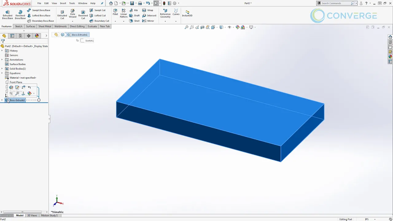
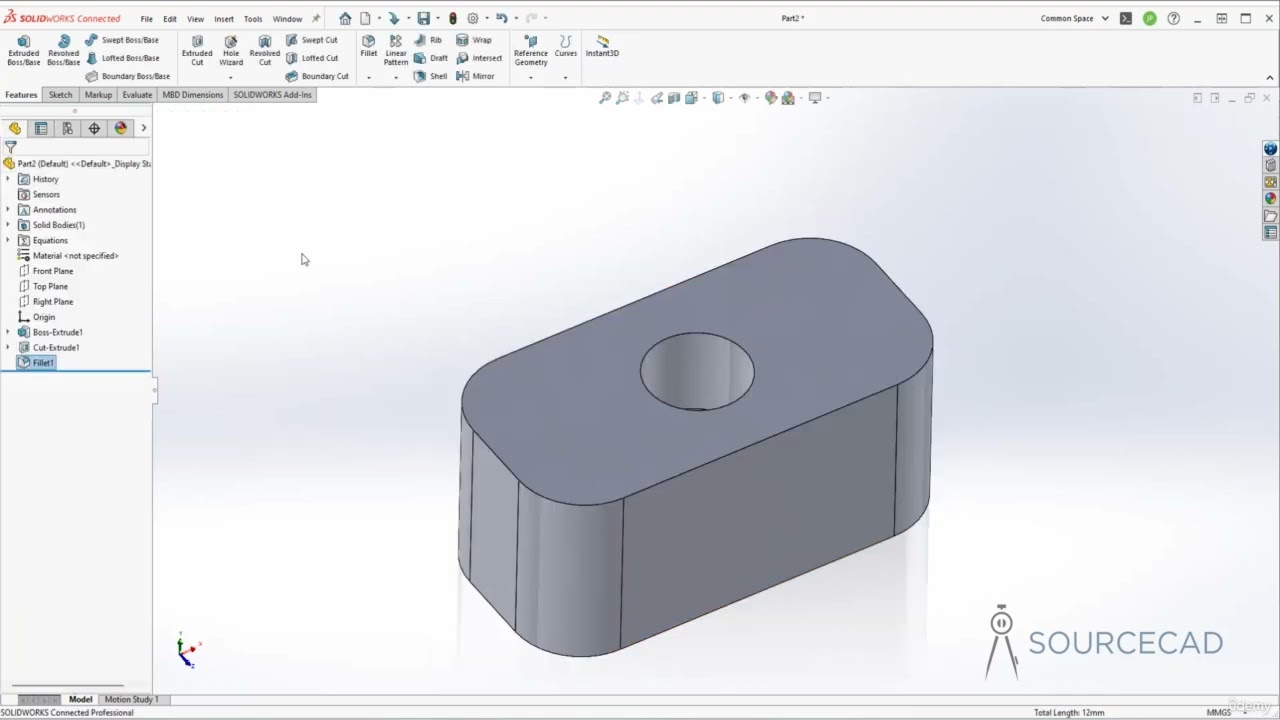
And exit check mark. Okay. Do an extruded extrusion based on this circle.
So let's go to the other way. Uh give a face one inch should be enough. Okay. So that's face width.
Okay. So that's the gear body. All right. So now next is we're going to create a few more circles on this surface here and which is the front plane. Right. So let's look at the front plane and let's do a few more circles here. First circle is the peach circle.
Second circle is the base circle.
Third circle is the denim circle. So then let's dimension all of them here.
So just check mark for all of them.
So we're going to use equation to drive all of them. Okay.
Okay.
Okay. So now let's go to our equation.
Okay. So uh after first usage of equation now we have this icon equation in here. So click on it right click manage equation. Okay. So first is this uh pitch circle. So here go to this cursor here. Click on the pitch circle.
That just equal to DP right. Yeah. So that's peach circle diameter.
Then we go to our base circle and base circle is DB which is what we already calculated. So that's just the DB.
Okay. And the last one is going to be the uh dendum circle. Dendum circle is dp minus 2 * b.
So that's denom.
Okay. So that should be all right. Okay.
So yeah, let's update. Click this button here to rebuild everything. It's updated. All right. So now we need to go back to this sketch here. Okay. to draw the involute curve. Now involute curve as as indicated in the lecture in the lecture also in this tutorial. Uh they are uh they are um uh basically represented by the by this parametric equation.
Uh we're going to draw basically two involute curves. Uh one is we're going to draw basically like one is this portion and the other is this portion.
Okay.
So this portion A right is represented by this parametric equation. This portion C which has angle beta in between is represented by this parametric equation here. The r is essentially the radius of the big circle. Okay. And t is a time varying parameter. Okay. So uh we'll deal with this beta angle here that has to be calculated properly. So but let's create this uh uh involute curve uh starting from this location a here using this parametric equation. Uh I have uh entered you know part of this uh parametric equation using notepad here. So notice that this portion here that's not r right but it's this one here. So what this is basically I don't want to enter a constant r here. are you only using a uh parameter driven uh radius r here. So unfortunately for solid works the equationdriven curves you cannot use global variable in this equationdriven curve. You can only use okay uh you can only use a dimension here to drive this number. So the the dimension here I use is basically dimension of the base circle diameter.
This is the dimension of the base circle diameter and divide by two. That will be the radius, right? So let's use this to create the first involute.
Uh go to the sketch. Okay, we're in a sketch now. Uh click on this equationdriven curve. If you don't have this icon here, you can go to tools.
Uh you can go to tools. Okay. And then sketch entity. So tools, sketch entity.
and then equationdriven curve. Okay, so here that's fine. So now let clear choose parametric first one here. Copy paste.
Okay, so you can enter by hand. Oh, here we go. So we're going to start from zero. That's basically starting from the a location. Give a value 6.8. Okay, 6.8 here. So that's there. There we go.
That's part of the involute there. So click yes. Good. Okay. So that's our involute here. Right. Yeah.
Now we're going to uh draw a line here connect to this point. Okay. Yeah.
So uh this is horizontal apparently.
Then we're going to draw another one here. Okay. Let's draw a center line.
So yeah, center line. Make sure the center line snap to the uh addendum circle at here. Okay. So, snap on it.
Okay.
Yeah, this is kind of a tricky. If you don't snap on it, it might cause some problem uh later when we changing the number of T's in the dimensional pitch though like that. Okay. So, then uh dimension the angle between okay between this uh these two lines here. Okay.
Okay. So this currently so we're going to constrain this angle here. So the question is uh how much shall we constrain this angle here. So let's go to our tutorial notes set here. Okay.
There's a a drawing of the geometry for uh based on two adjacent two set here.
So this is a pitch circle. This is the base circle and this is the concentric uh or uh center. Okay. for all the circles um n here is a number of teeth. So if you have any number of teeth then the angle corresponding to one circular pitch this is a circle of pitch here right circular pitch is defined as the the arc length from uh the point at here to the adjacent point along the pitch circle.
So this angle here basically this whole angle here is going to be 360° by by n okay because there are n number of t's okay any number of instances so this is the uh 360 in then and then the other thing is the width of the width of a space this is the width of space is the same as the tooth thickness okay so that means this portion of angle is or this portion angle is same as this which is 360 by 2nm. Now if I draw a center line here and here so basically I will have a four even right uh values or angles at here. Okay for even ones and that's basically if you look at this portion here this red line here is the connection the radial line between this point to the origin to the center and this is the center line here and that's basically this one and uh this center line here right? Yeah. Okay. So the point is what will be the angle between this red line this center line and here.
So that will be the angle would be 360° / 4N right this angle or this one here.
Okay. Minus this little angle alpha at here.
So this alpha angle at here. Okay. Uh it can be obtained through a g geometry here. So I didn't include the detail in the tutorial for the alpha here. So if you're interested, you can come to my office. I'll show you how the alpha is obtained. But overall the alpha is obtained as this. This is the expression for alpha here. All right. Yeah. So the alpha angle is basically angle between this dash line and this red line at here. Okay. So that means uh we need to dimension okay this angle here. Okay.
as 360° / 4n minus alpha here. All right. So let's go back to our uh to our drawing here. Okay. Go to our equation. Okay. So let's first let's define our alpha.
Okay. Define alpha here. And I already had alpha entered here. So I'm going to basically copy paste alpha.
Okay. Yeah. So you might notice that there's a mult multiply by 180 divided by pi here. So what this is basically um is basically this this is this portion here default is radant. So I'm going to change that to degree because the fine is 20°. So either way, you know, basically we want a degree here and then here change the degree minus 20° and that's what this is, right?
That's what this is. Okay, that's what this is. So that's alpha here. Then now I'm ready to dimension this one here.
This is D4. And uh what do we see about that? That's 360 / 4 * n and then minus the alpha there.
Okay, there we go. So that's that dimension over there. Okay, so click okay.
Okay, so uh double click that.
So let's update that.
Okay, so 4.15. So that's good. Okay.
Yeah. Now the next thing is we need to create that uh that involute starting from here. Okay.
And the angle between the C and A here is beta. So basically the angle and here which which is what which is uh twice the beta is twice as much as this portion here. Right? It's this and uh the the two in blue is these two here. Okay. So in other words, the starting location of that here right here is twice as much as this angle at here.
Now parametric equation wise okay your uh location starting the C here is this one here as indicated here. So that uh beta angle should be entered here. So essentially basically what happens is you change the t t here into negative t negative t. Okay. And because the started the starting location is here with the beta. So that's why we minus beta minus beta minus beta minus beta.
Okay. Yeah. So here's my inner uh expression. Here's my expression for um for the x and y here. Okay. uh for x here is this.
So as you can see uh here there's a two times this one and here. So that's basically a two times the dimension that giving me the beta here and then I convert the value into read into readings. Okay, because in equationdriven curve parametric equation the requirement is you you can only use readings for cosine and co and s right.
So here is that uh x here. So let's go here. So enter uh click on equationdriven curve parametric.
Okay. And uh go to the other one there.
Click that. All right. So that's same thing there. 068.
Okay. So there we go. That's our uh other part of the inglute curve.
Okay. So then I'll do the similar thing here. I'm going to connect here to here.
Right. Yeah.
Okay. So then we're going to dimension this and that. Okay. Ass it is. Okay. So this dimension here we're we are going to um also use equation to drive this angle at here. Okay. Yeah. So uh and sorry now this one here equation go to here equation manage equation.
Okay. So in this bunch add the equation here add this dimension here. So that dimension is going to be the same as D.
This D5 is same as D4. This is 360 divided by 4 * N - alpha here. All right. Okay. So okay. So there we go. So we got this uh n here now. So now let's um uh let's temporary exit it here. Okay.
Temporary exit. And uh uh we can try to change this number here. Let's see if that's going to be automatically updated. If I change 36.
Okay. So you can see it's automat updated here. Right. Okay. So I'm going to go back here and change back to 18.
Okay. All right. So uh now we're going to do a little house cleaning in here.
uh to trim off some of the curves and ready for the next step. Okay. So, first uh let's turn this two curves these two circle into uh construction lines. Okay. And then let's uh trim off here.
So, let's trim this off and trim that off there and trim this off. There we go. Okay.
Uh before we exit it here. So, we uh uh we're going to do one more thing here.
We're going to add a relationship or constraint in here, right? So click on this little segment of a line here and then press control click on this origin in here. Okay. And then click on coincidence.
Okay. Yeah. So basically we make sure this little segment here, okay, is going to the the extension of this segment is going to intersect always intersect this origin at here. Okay. So that's kind of critical cuz u I had some uh problem uh um when I was updating and p or p later but u um with this one will solve the problem. So okay so that should be all right now. So then let's exit here. Okay now let's do a little extruded cut. Okay based on sketch.
Okay so we're going to cut based on this sketch right here. Okay. So cut it through them all. Okay, there we go.
Okay, so that's a nice and neat cut. And then um we will um so let's do let's uh putting a fillet at these two edges in here.
Okay, so before we do a fillet, yeah, let's Okay, let's do a fillet here.
Okay, fillet this one and this one and here. Okay, the fillet radius should be smaller than the uh clearance, right?
So, right now the clearance sitting at um uh.125. So, that's okay. So, uh let's click now. Okay, that's a clearance there. Uh last step is to do a circular pattern. Okay. So, we're going to circular pattern around this surface here with not just a fillet but also this extruded cuts. Okay. So, that's it.
Okay. There we go. So, that is the gear.
Okay. Based on the given um values. All right. So now we can try let's see now if I uh going to have a different u let's say parameters. If I choose probably six out of here. Okay.
So all the calculation is updated and then click okay. Uh so you will have updated this one here. Uh so don't trick it here. So you see you might need to update sometimes you might need to update this fillet radius okay manually here fillet radius. Okay just in case uh if the if the fillet radius appear to be too big.
Okay. So if I change this number of teeth that are here. So maybe I'll change that to 36.
Okay. So okay. So 36. Yeah. So it looks funny though. But remember this circular pattern here should also be changed accordingly here. Okay. Cuz the region is 20. So we need to change that to 36.
Okay. Okay. So there we go. That's 36.
uh the fillet radius you see the C is 04 so the fillets here uh should should be updated slightly here so let's see maybe use a 0.5 zero five okay that's that's about it and um so those are nice and neat uh curves Okay. So if uh I actually compile comp compared the results here with the pro um um commercial software called gear tracks. So the the profiles and uh everything looks very uh very much the same thing. Okay. Yeah. So um that's the end of this tutorial and uh if you got a questions uh please let me know. Okay.
So it's it's going to be good exercise and I will try to create another video uh to show you how to properly mate a gear and a pinion. Okay. So this is basically part of the course projects and uh this is the modeling part right.
So you can uh if you can done this properly then uh you have done a portion of the project already. All right. Thank you.
Up Next
How to Calculate Gear Ratios in a Planetary Gear Set
@JustinMillerAutomotive
318.5K views•2015-02-20

Ultrasonic Transducers: Resonant Frequency Measurement and Horn Design
@imajeenyus42
229.9K views•2017-02-22

Polymer Environmental Degradation: Mechanisms & Stabilization
@iit
1.8K views•2012-07-10

How a Student's Question Saved a NYC Skyscraper from Collapse
@veritasium
22.8M views•2025-04-26
Related Study Plans & Knowledge Roadmaps
Structured learning paths in Engineering