








![Most cheap energy with self made biogas [ DIY Stirling micro CHP ]](https://i.ytimg.com/vi/QPeLWsZo01M/maxresdefault.jpg)


![수질환경산업기사 실기 필답 21년 3회 [구민사]](https://i.ytimg.com/vi/XzSmAihkUZs/maxresdefault.jpg)






High-rate anaerobic reactors overcome the limitation of long detention times in conventional anaerobic systems by maintaining high biomass concentrations through immobilization on support media (anaerobic filters, fluidized/expanded beds) or through solid-liquid separation with biomass recirculation (anaerobic contact process, UASB reactor). The UASB reactor, developed by Lettinga in the 1970s, is the most commonly used high-rate reactor for municipal wastewater treatment, featuring an anaerobic sludge blanket where wastewater flows upward through flocculent sludge, with a Gas-Liquid-Solid Separator (GLSS) at the top that separates biogas, liquid effluent, and biomass, allowing the latter to return to the digestion zone. For municipal wastewater treatment in tropical countries, a hydraulic retention time of 6 hours is typically sufficient to achieve satisfactory COD removal efficiency, with reactor height limited to 6 meters to prevent sludge washout.
Anaerobic Wastewater Treatment Reactors | Conventional & High-Rate Systems Explained
Added:Oh s.
[Music] [Music] Love me.
[Music] as we were discussing about and anobic treatment. We have seen what is the difference between anobic treatment and aerobic treatment and what are the different biochemical pathways involved in the anrobic degradation. And we have also seen what are the conducive environmental conditions for the better performance of anobic processes and we have seen the different types of bacteria involved in the process and what is the role of each bacteria and what is the nature of each bacteria.
Today we will discuss about what are the conventional and modified reactors available which is using anobic technology for the treatment of waste water. So coming to the conventional anorobic treatment systems or classical anorobic treatment system. The septic tank was there from 19th century itself.
It was invented by Cameron in England.
He was the first person who has used this septic tank. Septic tank is nothing but a tag which allow the settlement of suspended solids in waste water and the settling time is so large that means it it gives a time of five to 10 days. So during this period whatever is a suspended solids present in the waste water will be settling down and the tank will not be having any oxygen supply. So what will happen the sludge which is settled in the bottom of the tank will be under and conditions. At this conditions, anorobic bacteria will prevail and the solids will be undergoing anorobic degradation. So as a result, what will happen? The organic matter present in the system will be getting reduced and biogas will be produced. The bio gas will be coming from the bottom of the system to the top. So because of this biomass movement, some of the solids may be getting floated. This is an this is a disadvantage of the septic tank. I'll show the picture of the septic tank. So this is the one. So this is a reactor or any closed container and it is not open to the atmosphere only one when pipe is there and influent is coming like this and enough detention time is provided so that all the organic matter in the suspended form will be settling down and you'll be getting a sludge layer here. The sludge layer will be having so much of organic matter and the oxygen availability is almost nil. So end system will be under anorobic condition. So as a result what will happen? This sluds under goes anorobic decomposition and biogas will be produced as byproduct.
This bio gas will be coming in this direction in the upward direction and settling will be taking place in the downward direction. Due to this bio gas movement there will be some turbulence.
So as a result some particles whatever is already settled may come up and it will float in the surface of the septic tank. That is one of the disadvantages of this septic tank and whatever the scum and oil present in the influent that will be definitely coming up to the bottom of the tank. So usually in a septic tank there will be a scum board which prevents the scum to enter in the effluent channel. So the scum will be retained here and whatever is the treated effluent it will be coming out through this one. So what is happening in system? The organic content of the waste water will be decreasing drastically because influent will be having lot of suspended solids and all the suspended solids will be getting removed from the system and the effluent will be having only the soluble cod whatever is coming out along with the effluent and a part part of the soluble cod also will be getting removed in the septic tank. So this was the conventional anorobic system which was used in 19th century in the first anrobic reactor which was being used in the world and imov card. This is another anroic unit which is conventionally used. This is a modification of septic tank because I have already told in septic tank because of the bio gas movement the solids can float. So in septic in imoff con or imoff tank it is impossible because here we can see that here this arrangement separate the digestion zone and settling zone and gas or the bio gas produced due to the anobic digestion is not coming or not entering in the settling zone. The bio gas will be stored this portionally in the digestions only. So there will not be any turbulence created in the system. So what will happen? And you'll be getting relatively clear effluent in the M of tank. And this is the vent through which the bio gas is removed from the system.
And all the digestion will be taking place here. And this is the sludge layer. And this portion enta portion will be acting as the settling zone and the effluent will be collected from here. So you'll be getting much more clarified effluent from the im tank compared to septic tank.
And if you see the history, we can see that the first biggest public health system or environmental treat or wastewater treatment system employed was in Chicago in 1935. There they have used this im tank in series. The treatment capacity of the system was 1.8 million lit per day. So the first treatment system in the history of environmental engineering was made up of this of cons then or of tanks. So what is the problem? Why this anobic technology is not coming into existence or it is not becoming popular even now. Okay, we'll see the reason in detail after a while.
Okay. And the conventional anorobic system is the anrobic lagoons that we have discussed in detail when we were discussing about ponds and lagoons. So in anroic lagoons what is happening is we can go for high organic loading and the waste will be staying there for a long time. So what will happen because of the high organic loading rate whatever the air entering or whatever is oxygen entering from the atmosphere will not be enough for maintaining an and anobic aerobic condition in the system.
So entire pond will be in androbic condition. So what will happen because of the anrobic bacteria degradation will be taking place and a portion of the cod will be getting removed from the system.
So if you talk about the efficiency of this anorobic pond if you give sufficiently long detention time say 10 days 5 to 10 days then you'll be getting an efficiency of 50 to 70%age or we can find out the efficiency using this empirical formula 1 - 2.5 by HRT raised to 050. Here is the hydraulic retention time in days. So this is the expression derived from many field experience or they have studied many field anorobic pawns and they have evaluated the performance and from that performance they reached this empirical equation. So we can see that the HRT is in the range of 5 to 10 days. So the volume of the reactor required will be very very high.
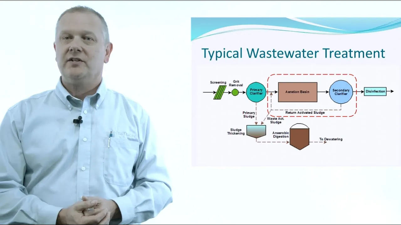
So that is one of the reasons why and anobic process did not become popular for domestic waste water treatment because the anobic treatment was the first one come into existence in 1935 as a treatment process but afterwards aerobic system took over anobic process because aerobic system we can achieve very high efficiency say 90 to 95% within few hours usually we give 8 to 10 hours HRT in the aeration time. So compared to this one, anobic system request lot more time. So naturally the volume of the treatment system will be very very high. So if we can reduce the detention time definitely the treatment system will become more attractive. The reason is we have seen that anorobic process is having many advantages over aerobic process. If you are the energy requirement is very very less because in aerobic system we have to airate the waste water. We have to supply oxygen externally to meet the oxygen requirement. But in anroic process oxygen is not required at all because the substrate will be acting as the electron donor as well as electron acceptor. The another reason is the sludge production. Anobic process we have seen that the organic matter whatever is used for the anabolic purpose or for anabolism or for cell synthesis is very very less less than 10%. Whereas in aerobic process it is around 40 to 60%age. So definitely the sluds produced in anobic process is much much less compared to aerobic process.
So handling is not a problem at all. And moreover the whatever is generated in anobic process is almost mineralized. So we don't have to go for any further treatment. We can directly put it into drying beds. So anobraic process is having many many advantages over aerobic process but the most important disadvantage is this one it take large detention time to get high efficiency. So if you can overcome this one anobic process will definitely become popular. So to avoid that one or to make anobic process popular. Okay, people were working in this area for a long time. So they have come up with this high rate processes. In high rate processes, what is happening is the system is able to retain high concentrations of active biomass. Okay, that means the microbial concentration in the system will be very very high.
Okay, we have seen that the regeneration time or the reproduction time of this anorobic bacteria especially the methanogen methogens the miden producing bacteria is very very high. If the regeneration time or reproduction time is very high naturally the biomass concentration will be very less. So if you are allowing the biomass whatever is generated in the system to go out what will happen the system will not be having enough biomass. So naturally the treatment efficiency will be coming down. So if you can clearly divide the hydraulic retention time and biological sludge retention time then the system can hold lot of biomass inside. So once the biomass concentration inside the system is very very high naturally the treatment efficiency will be high because in any biological system as I have already told many times the workers are microorganism. So if you can increase the number of workers definitely the treatment efficiency will be more. So that is the very principle of this high rate processes.
So now we'll see what are the mechanism of sludge retention in high rate anorobic systems. So the sluds can be retained basically in two different ways. one is the systems based on immobilization of the sludge and another one is systems based on liquid solid separation with the return of the separated solids to the reactor.
When we talk about the systems based on immobilization of sludge, the reactors which are working under this principle are upflow and downflow anorobic filter, slush bed reactors such as granular but expanded or fluidized reactors. So in these cases what is happening some inert material is there either it is sand or plastic media or any synthetic media on that the biomass will be growing. So naturally the medium will be having high density so it will not be going out of the system along with the liquid. So whatever the biomass generated in the system will be staying inside the system. So definitely we'll be increasing the biomass concentration.
And in the second system what we are doing is this is a form of modified activated process. So in activated sluds process what we are doing in the aeration tank we have lot of microorganism. So we are allowing the microorganism to settle in the secondary sedimentation tank and we want to maintain a high concentration of biomass in the aeration tank. So what we do the settled biomass whatever is there in the secondary sedimentation tank we allow a portion of that one to come to the aeration tank. So naturally the biomass concentration in the aeration tank increase. So the similar system works in anroic process also. So there we provide some arrangement which can easily separate the solid and liquid from the effluent and the solid will be coming back to the system. So this arrangement can be provided either within the system or as a separate unit. So depending upon that one we can see different types of reactors. So we'll see the reactors whatever is commonly used or the reactors which is working on this high rate principle. We'll discuss in detail.
So these are the anobic filters. So this one is upflow anobic filter and this one is down downflow anobic filter. So here what is happening is here we can see this dash lines. This is the filter media. This can be any inert material on which microorganisms can grow fast. So the effluent influent will be going like this and active biomass will be growing in this filter media. Just like our trickling filter or rotating biological contacttors the biomass will be growing in this filter media. Only thing the entire system is in anroic condition because nothing is open to the atmosphere. So no entry of air will be there in the system. So influent will be going like this and the organic matter whatever is present in the influent will be coming in contact with the biomass in the filter and the biomass will be utilizing the organic matter and some more new cells will be generated and the remaining part will be converted to carbon dioxide and methane and the bio gas is collected here. This system, these anobic filters are commonly used in industrial waste water treatment where the organic loading is very very high. Okay. This system can take lot of organic loading in the range of 10 to 20 kilogram per meter cube. That is the organic loading rate. And one of the problems which is usually faced in this type of filters is clogging. Because with respect to time what will happen?
The biomass concentration or biomass thickness in the filter will be very very high and that will be slowly increasing the porosity of the medium and filter clogging can take place and the reason for the clogging is this influent will be having lot of suspended solids. So that suspended solids will be coming and sitting here in the bottom portion of the filter. So that can also clog the filter. So what will happen afterwards?
There may not be sufficient flow and lot of head loss will be there etc. And sometimes if the influent flow rate is not sufficient what what usually is done is recirculate a portion of the effluent theta effluent here so that it will get enough velocity for the flow. So this is anrobic filter and now coming to the downflow fixed bed but anobic filter.
Here the influent is coming from the top of the filter and effluent is collected from the bottom of the filter. And here we can have the bio gas collection system and this is the filter media and on which the biomass will be growing.
The advantage of this system is the influent is coming like this and biodegradation is taking place. As a result the biogas methane and carbon dioxide will be produced. the gas will be going in the upward direction and the influent will be coming in the downward direction. So because of that one a proper contact between the waste water and the microbial system will be taking place because lot of turbulence will be created in the system. So short circuiting clogging etc can be minimized if you go for a downflow fixed bed anorobic filter. So these two are examples of high rate anobic anobic reactors. Now we'll see another type of high rate reactor. So this is the example of a fluidized bed reactor. So here what happens? We use sand core or any plastic media on which the microorganisms can grow as the supporting material. So in the reactor we'll be putting the supporting material and with respect to time what will happen? The microorganism whatever is present in the system will be getting attached to the inert material or the support material whatever we have provided here the support material will be having high concentration of microorganism and the influent will be coming from the upward direction. So from here it will be entering and it will be going in this direction and influent flow velocity will be very very high. So that the medium will be in the fluidized form.
That means one particle will not be in contact with the other particle.
Everything will be in a fluidized form.
So as a result of this fluidization what happens? There will be very good contact between the microorganism as well as the organic matter whatever is present in the waste water. So the treatment efficiency will be very very high and whatever the bio gas produced it will be going from here and we can collect the treated effluent from here because the microbial growth is in the form of attached microbial growth is attached one here the effluent will be relatively clear because not much microorganisms will be coming out along with the effluent and in this system the recirculation of effluent is most of the time a mask. The reason is influent may not be having enough velocity to fluidize the bed depending upon the bed material because if it is sand particles you know the specific gravity is very very high. So we need a very high upflow velocity to fluidize the material. Most of the time we recirculate the treated effluent to give the enough upward velocity here.
And now coming to the expanded reactor.
This is an example of expanded bed reactor. Here all the particles will not be in the expanded form. All the particles will not be in the fluidized form. Okay. Here the velocity the infl or the up upward velocity will be relatively low compared to the fluidized system. So the bed will be expanding up to 30%age of the initial height. Say initial height was only up to here.
after the influent passes. It will be expanding up to here. So how can we distinguish the fluidized reactor and an expanded bed reactor? There is no clearcut distin distinction between these two. But if you see the expansion, if the expansion is less than 30%age of the original bed height, then we call it as an expanded bed reactor. And if the expansion is more than 30%age, we call it as a fluidized bed reactor. The advantage of expanded bed reactor compared to the fluid fluidized bed reactor is here the recirculation is less compared to the expanded fluidized bed reactor because here we want to expand it only 30%. So the velocity will be less compared to this reactor. So the pumping cost can be reduced in expanded bed reactor compared to fluidized bed reactor. But efficiency by expanded bed reactor efficiency will be lower than fluidized bed reactor because here you'll be getting more contact with the biomass and the organic matter in the waste water.
Now we'll see the type of system. So the one we have discussed so far the anthropic filters and fluidized and expanded bed reactors are working on immobilized reactor systems. That means some inert material we are providing on that the microorganisms are getting attached. So those these two reactors whatever we have seen now the anobic filter downflow fixed bed anobic reactor expanded bed reactor and fluidized bed reactor all these four are coming under immobilized reactors because the bacteria are growing on some support medium. The support medium can be some natural material or synthetic material.
If you use synthetic material especially the plastic and like substances what will happen the specific gravity of the substance is specific gravity of the particle is low.
So the velocity required to fluidize them or expand them expand the bed will be less. So pumping cost can be reduced drastically. Now we'll come to the systems which use the solid liquid separation process and after that one the slides will be recycling to the system. So that way we can increase the biomass concentration in the system. So this is the example of an anorobic contact process. So this is the anorobic chamber. The influent is coming here and digestion. This is the digestion zone.
So anobic reactions will be taking place. As a result the bio gas will be produced and we'll be getting the effluent through this one. Because of this bio gas production what will happen? Entire reactor will be getting mixed up thoroughly. If the mixing is not proper we can provide the mixing externally also. So definitely whatever the biomass concentration in the inside the system same concentration will be coming out along with the effluent. So here we are collecting the effluent and allow it to settle. So this is a settler or a sedimentation tank. So here all the biomass whatever is coming along with the effluent will be getting settled and all the biomass will be recycled to the system along with the influent. So we can see here. So what will happen the biomass concentration in the system will be very very high.
So we can reduce the hydraulic retention time considerably. So this is known as anroic contact process. Here the entropic digestion and the settler or the sedimentation tank are separate units. So the modified form of this and anobic contact process is the UASB reactor. So this is the schematic of a UASB reactor. Here what is happening? The influent is coming here.
We'll be having anobic bacteria here and the effluent will be going upward and we'll be collecting from here. But in the reactor itself some provisions are provided. So the reactor itself a portion of the reactor itself will be acting as a settling zone or a cmentation zone. So with respect to time the biomass concentration in the reactor will be very very high. So we can have a very high efficiency or we we'll get a high treatment efficiency within a short contact period. So what happens here? See we can see some projections here or deflecting beams here and we have some arrangement here also. So the waste the treated water will be coming here and afterwards we can see that this portion is getting expanded. So this portion will be acting as a settling chamber or a sedimentation tank and this portion will be acting as a reactor or nitration zone. Okay, this is a modified form of im tanks whatever we have seen initially and the treated effluent will be collected from here and bio gas will be collected from here. So here we are not providing any external unit for the biomass settling but the system itself will be providing the settlement of the biomass or the system will not allow any biomass to es escape along with the effluent.
So this is another type of reactor. So there is no separate GLSS that means gas liquid solid separator.
So this is the plastic cover. So influent is coming blanket is here.
Okay. And the velocity is adjusted in such a way that by the time the water reaches here or the treated water reaches here all the biomass whatever is present in the system will be coming back to the blanket. So by this way the biomass concentration in the system will be increased and this is another modification here instead of flowland sludge we use granular sludge. So what we can do is since the sludge is in the granular form the settling velocity will be very very high. So we can use or we can create a high organic waste or we can reduce the detention time considerably in such reactors. This is known as an EG SB reactor that means expanded granular slots bed reactor.
So all these reactors are coming under high rate reactors. Now we'll see the efficiencies of each reactor in detail.
So as I have already explained the anrobic filter we can go for very high organic loading that means in the range of 10 to 20 kilg cd per meter cube per day and it is mostly used for high strength industrial waste water treatment and the efficiency okay we can derive the equation for efficiency using kinetics approach but there are empirical expressions available if you want to find out the efficiency of the system.
The efficiency of this anorobic filter can be find out using this empirical formula. E is equal to 1 minus 0.87 HRT raised to minus 0.50.
Here should be in hours. We have seen in anroic lons the efficiency is given with by an empirical formula where the HRT was given as in days. But in anobic filter this HRT is given in terms of hours. Now coming to the expanded of fluidized reactor. I have already mentioned that attachment media is usually sand androite and plastic and usually and plastic are preferred nowadays. The reason is the pumping cost can be reduced considerably.
And if you want to find out the efficiency of an expanded band or a fluidized bed reactor, we can use this numerical formula. E is equal to 1 minus 0.56 HR to -0.60.
And as we have seen upflow anorobic blanket reactor and it was developed by Lettinga in 1970s and this is the most commonly used high rate reactor for municipal waste water treatment. Even in India we have many USB plants at present which is used for the treatment of domestic waste water and domestic and industrial waste water together. For example, in Kboard initially they have set up a 5 MLDD treatment plant for the treatment of domestic waste water and by seeing that it is a success they have put up another treatment plant which is having a capacity of 36 MLDD which is using domestic sea waste as well as the waste water from the tannary waste water tannary industries. So this is used for the treatment of municipal as well as industrial waste waters. So this is the example of an upflow and rubbish sludge blanket reactor because this is the one which is most commonly used. We'll see in detail what is happening in a USB reactor. So in USB reactor the influent will be coming from the bottom of the reactor and we can see that this is the influent distribution pipes.
So it will be entering in the reactor at different parts and you'll be having a anorobic sludge blanket that means a thick flock sludge blanket will be available in the reactor. So the waste water will be coming here and it will be entering in the anobic sludge blanket through the influent distribution pipe pipes. So what will happen the waste water will be passing through this anobic blanket. So definitely this anobic blanket is nothing but active microorganisms. So this active microorganisms will be coming in contact with the organic matter present in the waste water. So what will happen as a result biodegradation will be taking place and more and more new cells will be generated and as a byproduct carbon dioxide and mir gas will be produced. So everything will be moving together. That means gas, liquid as well as the solids will be moving in the upward direction like this. So this is the digesttor sound digestion zone of the reactor. And afterwards what we can see here a transition zone is there. So here we can see this one. This is nothing but a deflector beam.
And we have under arrangement like this.
So all these things together it is known as GLSS. That means gas, liquid, solid separation system here because I have I have already mentioned here all the three components that means the liquid the biomass as well as the bio gas will be coming up in this direction and we want to separate all the components separately that means we want to have liquid separately we want to have solid separately and we want to have gas separately. So that is what is taking place in this zone. So what will happen the bioolids or the microorganism it will be in the flockland form and the bio gas whatever is produced that also will be sticking to the microbial flock.
So as such the density of the flock will be less. So everything will be rising up along with the liquid because this liquid will be having an upflow velocity. So with the same velocity or almost the same velocity everything will be rising up. So once it comes here okay if it hits like here what will happen okay the gas whatever is present in the flocks okay microbial flock it will be getting separated from the flock. So once the gas bubble gets separated from the flock in the apparent specific gravity or apparent density of the microbial that flock will be increasing.
So definitely the settling velocity will be increasing. So the microbial mass will be going out like this. And whatever is the gas bubbles released it will be coming and getting collected here. And as we see okay it will be some portion of the liquid and some microorganism or some flocks which is not yet removed from the system will be coming out through this portion.
So we can see here the cross-sectional area of this portion is very very less compared to this portion. So what will happen to the velocity of the liquid coming out through this portion the velocity will be gradually decreasing as the cross-sectional area is increasing.
So because of the velocity gradient and due to the settling velocity the flux the microbial flux will be getting settled here and only clear liquid will be going up. So whatever the settled slots whichever is present here because we can see that this is an incline plane. So because of the sulfate whatever the slots collected here everything will be coming back to the system and all the slots will be getting collected here. So we are getting clear effluent from the from this portion and all the microbial mass whatever has escaped through this portion also we'll be coming back to the digestion zone and we'll be getting the clean or the bio bio gas through this portion. So this system along with the deflector and the face separator element is able to separate the gas the liquid and the solids and retain a high microbial concentration in the system. So this is a typical UASB reactor and it is having three zones. One is the settling zone, another one is the digestion zone and third one is the transition zone. And if you want to see the efficiency of the system here also we can use some empirical formula to get the efficiency of the system. The empirical formula usually used is E is equal to 1 - 0.68 HRT raised to minus 0.68. Here also here also the HRT is in hours.
So if you want to compare the performance of all these high rate reactors whatever we have discussed so far we can see that this is the retention time it is given in ours and this is the cod removal efficiency and this is the fluidized or expanded bed reactor.
So we can see that even at very low retention time the fluidized reactor is able to provide a high efficiency. Okay.
For a temperature greater than 20° centiggrade because temperature is very very important in anrovic process. As the temperature decreases the efficiency reduces drastically and this is the performance of a USB reactor up to 5 hours 6 hours. Retention time the efficiency is relatively lower compared to fluidized or expanded bed reactors.
But for high retention time say 10 hours the efficiency of fluidized and expanded bed reactors and USB reactors are almost the same.
And this is the performance of anobic filter.
We can see this one and this is the efficiency of anobic pond. And compared to all these things the efficiency of androbic pond is much less because here what is happening we don't have any mechanism by which we can maintain the microbial concentration in the system or in anroic pond the hydraulic retention time and BSRT are not clearly distinguished or we are not providing very high BSRT compared to hydraulic retention time in anroic pond that's why the efficiency or the cod removal efficiency of this anobic pond is much lower compared to all these high rate reactors. So the more microorganism we can retain in the system the more the efficiency will be and nowadays because we have seen that in UISB or aflow anobic sludge blanket reactor the reactor which is most commonly used for the domestic waste water treatment in tropical countries.
Okay there the sludge is in fllland form. So what will happen when the sludge is in fland form it settling velocity is very low. So if you give a high upflow velocity of the influent or the waste water what will happen or your sludge will be rising up and since the upflow velocity is very large compared to the settling velocity of the sluds the sluds will be escaping. Though you provide a proper settling chamber inside the system, we may not be able to capture all the microbial cells whatever is escaping from the system and it will be difficult to maintain a high concentration of biomass in the system.
So in USP reactors or whenever we use flint sluds the flow velocity is limited. We can go maximum of 1 m per hour. That means okay if you provide more than that the settling velocity of the slots will be very very less compared to the upflow velocity and it will be washing away from the system. So in order to avoid this problem okay because the limited upflow velocity if you want to give a high organic loading rate or high volutric loading rate okay we have to have a provision for changing the upflow velocity. So as a modification of this UASB reactor nowadays EGSB reactors are in use. EGSP reactor what we are using instead of local slots we are using granular sluds.
The slots themselves without the help of any inert material. The themsel themselves will be forming a granular of 3 to 5 mm and definitely the granular will be having a very high settling velocity compared to the flowland sluds.
So because of this high settling velocity we can use a high upflow velocity or even the waste water enters in the system with a high upflow velocity the sluds will be remaining in the system. So that is the modification of USB reactor. It is known as EGSP reactor expanded granular slud reactor.
Another one is a anorobic sludge blanket. It is a sludge blanket. Here it is a granular slud bed reactor. And as I have already mentioned the granular the diameter varies from 1 to 5 mm and it is having high density and it is having excellent mechanical strength high settling velocity and high specific methogenic activity because the sluds or the gran granule will be having different types of microorganisms staying together. So definitely the gas liquid contact will be very high. So it always show a high specific methogenic activity and there are some disadvantage for this system in AGSP reactor inadequate for the removal of particulate organic matter due to the high upflow liquid velocity. Okay. This AGSP reactor is very very good for the treatment of waste water having dissolved organic matter. But if suspended organic matter is there the treatment efficiency will not be very very high. The reason is the organic matter whatever is present in the waste water will be having a very low density. The density will be in the range of 1 1.05 1.01 to 1.05 in that range. So what will happen if you have a very high upflow velocity it will be going along with the liquid the waste water whatever we are giving to the system. So it will not be having enough contact with the microorganism whatever is present in the system. So the suspended solids will not be getting removed from the system or the suspended solids will not be biodegrading in the system because it will be washing away because we know that if suspended particles are present in the system first hydrarolysis has to be taken place then only the organic matter will be available for the microorganism. As suspended form it will not be able to penetrate through the cells of the microorganism unless it enters in the cells of the microorganism. microbial cells won't be able to metabolize them and convert it into bio gas. So that is a major disadvantage of EGSP reactor.
Now we'll see the another modification that is two-stage anorobic digestion.
As we have already discussed if suspended solids are there EGS the reactor will not be able to do a good job. So if you can separate the hydrarolysis step and the methogenic step okay the reactor volume can be reduced considerably. So in two-stage anroic digestion what is happening is the first stage is used for hydraysis and the second stage is used for methanogenesis. So in the first stage all the sus suspended matter will be hydrayed and getting converted to soluble acids and the pH of the system will be coming down because most of the time the hydrarolysis process is very fast and the reproduction time of this acid formers or hydra hydraytic and acid forming microorganisms are less compared to the methanogens. The slots production also will be high. So the activity will be more. So we we have to give only a low hydraulic retention time. Once the hydraulysis is taken place here, the hydrayzeed portion can go to a second stage where the methogenesis will take place. So this is a schematic of a two-stage reactor. So influent is coming here. This is the hydraytic reactor.
And whatever is the soluble organic matter after the hydraysis coming out it is coming here and it will go to the methogenic reactor and methogenic reactor here we can use EGSP reactor because we have seen that EGSP reactors are very very efficient to treat dissol waste water having high dissolved organic matter. So here what is happening in hydraulic reactor all the suspended particles are getting converted to dissolved organic matter and that is going to the AGSB reactor and we'll be getting the digested fraction here and we get the effluent here.
Now we'll see the design criteria for USB reactor because this is the one which is most commonly used in wastewater treatment domestic waste water treatment. So we'll see the design aspect of USB reactor in detail. So first we'll see the reactor shape and size for relatively low strength waste water like sea wage. Hydraulic loading is more important than organic loading. Okay.
Whenever we talk about the design of USB reactor that to low strength waste water like sea wage the hydraulic loading is more important than the organic loading because this organic loading will not be the rate limiting step. the hydraulic loading will be the one because if you provide a large hydraulic loading corresponding to the required organic loading what will happen you'll be ending up with a high upflow velocity.
So if the upflow velocity is more than 1 m per hour what will happen the sludge blanket whatever is present in the reactor will be rising up and it will be washing out from the reactor. So that will be drastically reducing the efficiency of the system.
So that is why I told hydraulic loading is more important for law strength waste water compared to organic loading. Now if you want to decide the size and shape of the reactor the USB reactor is having basically two important zones. We have seen three zones. One is the digestion zone. Another one is the settling zone and there is a transition zone also. So if you take the digestion zone and settling zone as the important things it is advisable to provide equal area for both that means 50%age of the reactor will be used as digestion zone and the remaining 50%age will be used as the settling zone and usually the hydraulic loading rate 6 hours of HRT is sufficient in tropical and subtropical conditions to achieve a satisfactory removal efficiency.
one if the temperature is low if it is in the range of 10 to 12° centigrade we have to provide an HRT of 12 to 14 hours to achieve the same efficiency because we have seen that for every 10° rise in temperature of falling temperature the efficiency will be decreasing drastically because in tropical countries the efficienc The temperature will be always above 25° centigrade. So that is the optimum temperature for anobic process is 35 plus or -2° centigrade. So at optimum temperature the hydraulic retention time required for achieving the desired efficiency is only 6 hours. But if the temperature is less then we have to provide a high hydraulic retention time.
And if you want to find out the volume of the reactor, we know what is the flow rate of the waste water Q. And if you multiply the flow rate with the hydraulic retention time, we will be getting the reactor volume. And this is the commonly practiced rule. If volume is greater than 1,000 m cube, go for multiple units. If the volume is less than 1,000, we can go for a single unit.
Now coming to the height of the reactor, we have seen how to find out the volume.
The volume is decided based upon the hydraulic retention time and the flow rate of the waste water. Now we want to see what is the height. We can provide the liquid upflow velocity decides the height because we have seen that this is the limiting factor of a UAS reactor.
And we can find out what is the VA. This is VI is nothing but the liquid upflow velocity that is equal to QI by area of cross-section. QA is the flow rate influence influent flow rate and A is the cross-sectional area.
So this is nothing but Q is the volume of the reactor by hydraulic retention time. So that will give you Q value because V volume is nothing but Q into HRT. So volume by HRT will give you Q. So Q by A gives us the velocity. So if you use like this we can see that the upflow velocity is nothing but h by hrt the area of this one and this one will be getting cancel and we'll be getting upflow velocity is nothing but height by the hydraulic retention time and we also know that this upflow velocity should not exceed 1 m per hour in anrovic system in USB reactor because the flowland slots will be having a very less settling velocity.
So if the settling velocity is less than the upflow velocity what will happen the SL wash out will be taking place. So this is the limit usually provided. So for an HRT of 6 hours the height should not exceed 6 m.
So the maximum height for the digestion zone in a US reactor you can provide is 6 m. And one more reason is there if you give more height what will happen the hydrostatic pressure in the reactor will be more. So naturally the CO2 solubility increases with depth. So if CO2 solubility increases once CO2 get dissolved in the water we'll be getting carbonic acid this carbonic acid will be reducing the system pH. So in this aspect also it is not advisable to go for a very high reactor.
Now coming to the shape we can provide rectangular as well as circular. If you go for a rectangular reactor, it is having less structural stability. But a circular reactor, it is having high structural stability. But construction is difficult. And nowadays people are going for even hybrid reactors. That means the bottom portion is circular and the top portion is rectangular or vice versa.
The bottom portion is rectangular and the top portion is circular. So these are the geometrical shapes of few USB reactor. This is a circular reactor. You can see this is the reactor zone and settling zone. And this is the gas collection system. And this shows a rectangular reactor. And this is a hybrid one. That means the bottom portion is circular and the top settler portion is rectangular.
Now we'll see how to go around for the design of face separator. This is the most important component of a UASB reactor. Gas, liquid, solid separ separator. Its functions are it collect the bio gas escaping from the liquid phase. So that is the gas separation and second one it allows the settling of suspended solids and it also helps to keep the effluent total suspended solids concentration law.
And the last one is it creates a space above the separator for the sludge spread to accommodate expansion due to high temperature and high hydraulic loading. So whatever is the excess loading coming to the system. So the reactor will be able to take care because it is having huge area above the solid liquid separator. So how to design a solid liquid separator? So this is the details of a solid liquid separator. So we can see that here a deflector beam is there and here the separator element is there and this is the interface between gas the bio gas and the liquid and this is the settler. This is a settler. So usually usual dimensions we can give deflector beam around 850 mm and here this portion is 640 mm and this is the separator element. It can have a width of 1360 and this portion okay this portion is 1150 or in other words the overlapping between the reflective beam and the separator element should be at least 100 mm that means at least 10 10 cm overlap should be there and what is happening the water the waste water solids as well as the gas will be coming here and There is a reduction in the cross-sectional area and this separator element is placed at an angle of 45° 45°. So the water will be entering here at a velocity VM and this VM is almost equal to 31 of V1 that means subflow velocity and we can see that the cross-sectional area is keep on increasing as we go up. So here the VDI will be equal to VI.
So what is happening here? We'll be having a high velocity and it will be gradually decreasing. So a velocity gradient is available. So fauculation can occur and this will be acting as a sedimentation zone also. So all the biomass will be getting settled here and this is having an angle of English of 45 because of this because of the sulfate of the slats whatever is settled here everything will be coming back to the reactor and this GLSS there are two possibilities to create a GL interface one is with a submerge separator and another one a separator situated above the water surface if the separator situated above the water surface. We have easy access accessibility but most of the time we go for submerge separator.
Okay, this is a separator with atmospheric pressure. Okay, because it is exposed to the atmosphere. Here we have easy accessibility and this is a hybrid one and this is a submerged one. So we'll see what all are the advantages of a submerge separator.
Definitely the corrosion will be high.
This is a disadvantage. But the entire reactor area is available for solid settling. The biogas will be released under an high pressure and external seal to provide explosion during flaring. So these are the advant advantages of submerged separator. So it is better to have a submerge separator if you can take care of the corrosion.
So these are the velocities. If you want to find out the velocities whatever is coming in the aperture and this is the discharge velocity A VP VA that is nothing but the upflow velocity of the liquid at the base of the GLS separator that we can find out. We know what is the Q and what is the closest area then we can find out that velocity and VDI which is the upflow velocity of the liquid at the effluent discharge level that also we can find out if you know the area at the discharge level.
So instead of providing the GLSS as a single row we can even provide under as different rows so that okay the efficiency will be much more. So if you want to see the principles of design of ags okay this one is very very important this portion we'll discuss in detail in the next class because we have to see how the influent arrangement the fluent arrangement and how to provide the inclination and all other dimensions of a GLSS this portion we'll discuss in the next class so we'll summarize what we have seen today we have seen what are the conventional anorobic reactors which were used in the earlier days. Those were the septic tanks and imoff tanks.
These septic tanks and imoff tanks are being used nowadays also especially in rural areas.
And here in these type of conventional systems the biomass retention was very less or we need a very high hydraulic retention time. So the efficiency was very very less or the volume of the reactor required was very less. So the entropic volume of the reactor required was very high. So Andropic technology was not becoming very popular. So so nowadays the hybrid reactors are available which can retain a high biomass concentration in the system. The examples of hybrid reactors which are most commonly used nowadays for the treatment of domestic as well as industrial waste water are anobic filters downflow stationary but anobic filters fluidized bed reactors expanded bed reactors upflow anroic slud blanket reactors granular sl reactors all these reactors are being used commonly Nowadays for the treatment of domestic waste water.
[Music] [Music]
Up Next

ESP32 WebSocket Server with Arduino and SPIFFS Web UI
@ShawnHymel
166.9K views•2019-09-09

Ultrasonic Transducers: Resonant Frequency Measurement and Horn Design
@imajeenyus42
229.9K views•2017-02-22

Microfluidics Introduction | Micro & Nanofluidic Devices
@iit
37.1K views•2015-06-22

How a Student's Question Saved a NYC Skyscraper from Collapse
@veritasium
22.8M views•2025-04-26
Related Study Plans & Knowledge Roadmaps
Structured learning paths in Engineering