




![Theory & Design of the Yagi-Uda Array Aerial [II][L][5].wmv](https://i.ytimg.com/vi/shpvcFjwdWQ/maxresdefault.jpg)

















![High Performance Antenna Build. [Part 3] The Mast Goes Up!](https://i.ytimg.com/vi/kCwfRPWv8_4/maxresdefault.jpg)
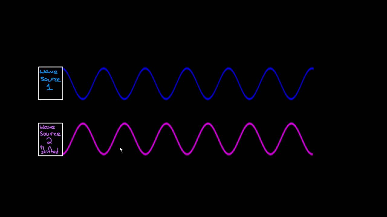
A Yagi-Uda antenna is a directional beam antenna consisting of a driven element (dipole or folded dipole) and parasitic elements (reflector behind and directors in front), where the reflector is longer than the driven element and directors are progressively shorter; the parasitic elements absorb and re-radiate electromagnetic waves from the driven element with phase differences, creating constructive interference in the forward direction and destructive interference in the reverse direction, resulting in a stronger signal in the forward direction and a weaker signal in the reverse direction (forward/backward ratio), with typical gains up to 20 dBi and front-to-back ratios up to 20 dB.
How Does a Yagi-Uda Antenna Work? | Beam Antenna Design & Function Explained
Added:Basic electromagnetic wave theory, including the relationship between frequency, wavelength, and speed of propagation.
The operating principles of a fundamental half-wave dipole antenna, which acts as the driven element in a Yagi-Uda array.
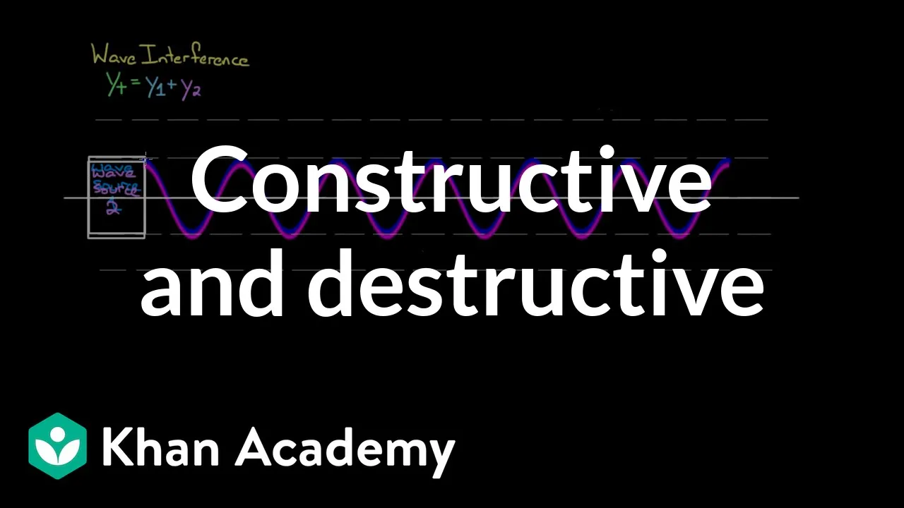
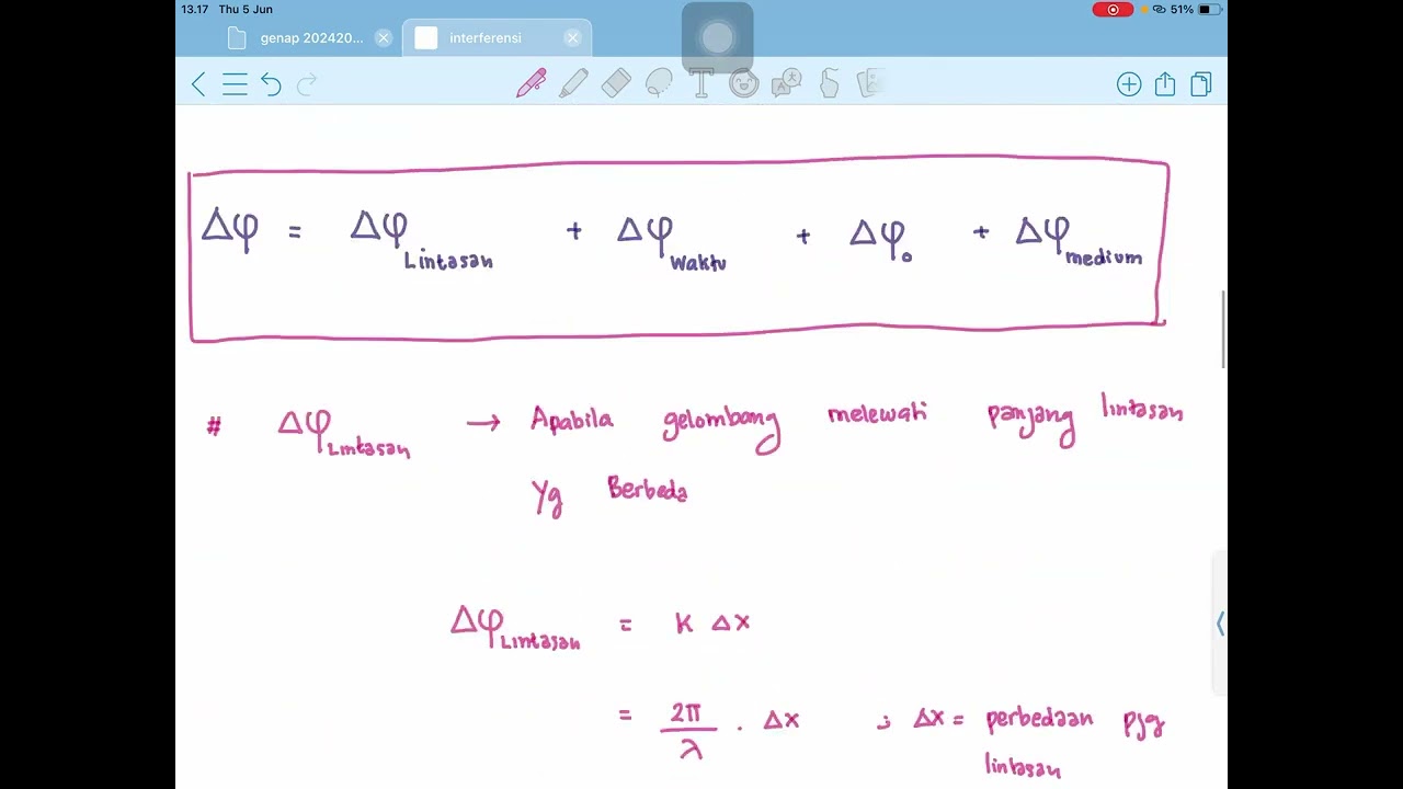
The concept of wave interference, specifically how phase shifts lead to constructive and destructive interference.
Basic antenna terminology and performance metrics, such as radiation patterns, gain, directivity, and impedance.
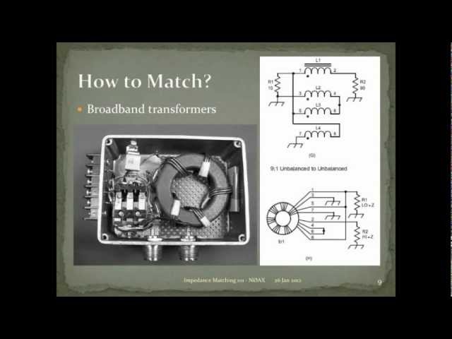
Practical impedance matching techniques for Yagi-Uda antennas, such as using Baluns, Gamma matches, or Hairpin matches.
Computer-aided antenna design and simulation using software like NEC (Numerical Electromagnetics Code) or EZNEC to optimize element spacing and length.
Advanced directional antenna architectures, such as Log-Periodic Dipole Arrays (LPDAs) and Phased Arrays.
Real-world deployment considerations, including polarization alignment, mast installation, and wind loading for VHF/UHF applications.
3.1K views38likes4:05Original Release: 2023-05-23
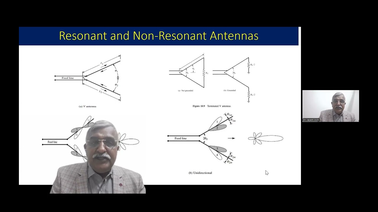
is very popular in a major radio or ham radio it is also a common sight on how stops before the era of cable TV and satellite TV it consists of a driven element and a variable number of parasitic elements on a boom The Driven element could be usual dipole or a folded dipole element behind the driven element is the reflector elements in front of the driven element are called directors typically the reflector is longer than the driven element while directors are progressively shorter than the driven element output the radio is fed only to the driven Element Animation illustrates how a foreign works there are two directors and a reflector in addition to the driven element dipole the parasitic elements act as resonators by absorbing and re-radiating the electromagnetic waves from The Driven element with the phase difference there is constructive indifference of these electromagnetic waves in the forward direction as they are in phase and destructive interference in the reverse direction as the waves are out of phase net effect is a stronger signal in the forward Direction and a weaker signal in the reverse Direction this is usually mentioned as the forward backward ratio of the antenna in the animation the signals are color coded similar to the antenna element for ease of recognition antenna is often called as a beam antenna in amateur radio due to the size it is less often used on HF bands than on VHF and UHF bands the number of elements practically feasible are also lower on Lower bands they are used with antenna rotators as good directional antennas antennas can have gains up to 20 DBI and front to back ratio of up to 20 DB radiation pattern is linearly polarized with horizontal polarization for a horizontally mounted antenna and vertical polarization for a vertically mounted one is relatively narrow with a narrow range of frequencies within a band at which it has good gain and operable feed Point impedance The Driven Elementor rate can be assembled dipole with two quarter wavelength rods connected to either conductors of the feed line in some versions it is a folded dipole which has a higher impedance of around 280 ohms the television antennas of yesteryears with folded dipole used to be fed using a twin lead transmission line with impedance of about 300 ohms folded dipole will need a matching for amateur radios with impedance of 50 ohms usual dipole has an impedance of around 70 ohms spacing between the elements may vary from quarter wavelength to one tenth of a wavelength depending on the design radiation pattern of yagi udantana is along the axis perpendicular to the plane of the elements towards the direction of the directors as the parasitic elements have zero are of voltage at the center they can be directly attached to the boom but this will electrically shorten them and usually a correction in length is needed to cover this there are versions in which all elements are insulated from the boom as well the two hours of the centiped dipole have to be insulated in the location of the Boom
Up Next

81:55
NEB Physics Crash Course: Sound & Wave Propagation (Day 4)
@ClampHook
2.1K views•2022-05-22

12:53
21cm Hyperfine Transition in Neutral Hydrogen: Radio Astronomy Basics
@AaronRobertParsons
12.4K views•2011-10-13

32:32
NMR Spin Physics I: Zeeman Effect, Resonance Condition & Larmor Frequency
@nptel-indianinstituteofsci8064
2.3K views•2024-01-17

27:14
Entropy and the Second Law of Thermodynamics Explained
@veritasium
27.5M views•2023-07-01
Related Study Plans & Knowledge Roadmaps
Structured learning paths in Physics
physics
Nuclear Physics (Decay, Fission & Reactors)
01Atomic Structure and the Binding Force
02Radioactive Decay and Half-Life
03Nuclear Fission Mechanics and Chain Reactions
+ 2 more learning modules
12h5 modules
Explore Roadmap
physics
Soft Matter (Polymers, Colloids & Rheology)
01Foundations of Soft Matter & Thermal Forces
02Polymer Physics and Macromolecules
03Colloids, Surfactants, and Self-Assembly
+ 2 more learning modules
38h5 modules
Explore Roadmap
physics
Analytical Mechanics: Lagrangian & Hamiltonian
01Mathematical Foundations: Calculus of Variations
02From Newtonian Mechanics to Constraint Dynamics
03The Principle of Least Action & Lagrangian Mechanics
+ 3 more learning modules
28h6 modules
Explore Roadmap
physics
General Relativity (Spacetime & Cosmology)
01Foundations of Relativity: Special Relativity
02The Geometry of Spacetime: Equivalence Principle & Curvature
03Einstein's Field Equations: The Mathematics of Gravity
+ 2 more learning modules
55h5 modules
Explore Roadmap