







![[LOS/T #1] Construindo um sistema operacional do zero](https://i.ytimg.com/vi_webp/pYZK1xiNMEg/maxresdefault.webp)





![Пишу на ассемблере, потому что Go — для идиотов ★ NOS [часть 3]](https://i.ytimg.com/vi/7_YzySR_7dI/maxresdefault.jpg)









This video demonstrates how to modify a simple x86 bootloader to print a message on screen using BIOS interrupt 0x10 with AH=0x0e, which prints a character from AL register; the process involves initializing segment registers (DS, ES, SS) to zero, setting up the stack pointer at 0x7c00, defining a null-terminated string with DB, preserving registers (SI, AX, BX) on the stack, using LODSB to load characters, checking for the null terminator with OR AL, AL and JZ, and finally calling int 0x10 to print each character to the screen.
x86 Operating Systems: BIOS Interrupt 0x10 to Print a Boot Message
Added:Basic understanding of 16-bit x86 CPU architecture, including general-purpose registers (AX, BX, CX, DX) and basic assembly instructions like MOV.
Concept of the x86 boot sequence, including the role of the Master Boot Record (MBR) and the 512-byte boot sector limit.
Understanding of CPU execution modes, specifically 16-bit Real Mode in which BIOS execution takes place.
General concept of software interrupts and how the Interrupt Vector Table (IVT) maps interrupt calls to BIOS routines.
Handling user input in real mode using BIOS keyboard interrupts (such as INT 0x16).
Loading subsequent sectors of the operating system from disk into memory using BIOS disk interrupts (INT 0x13).
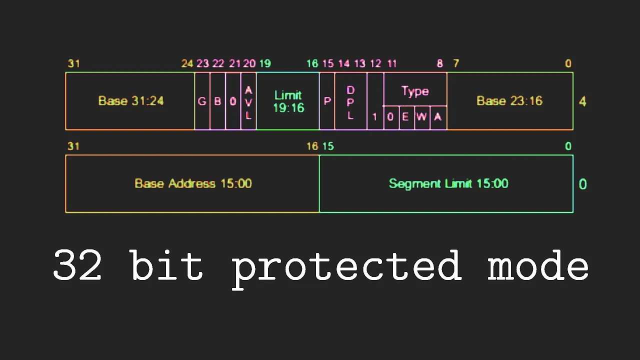
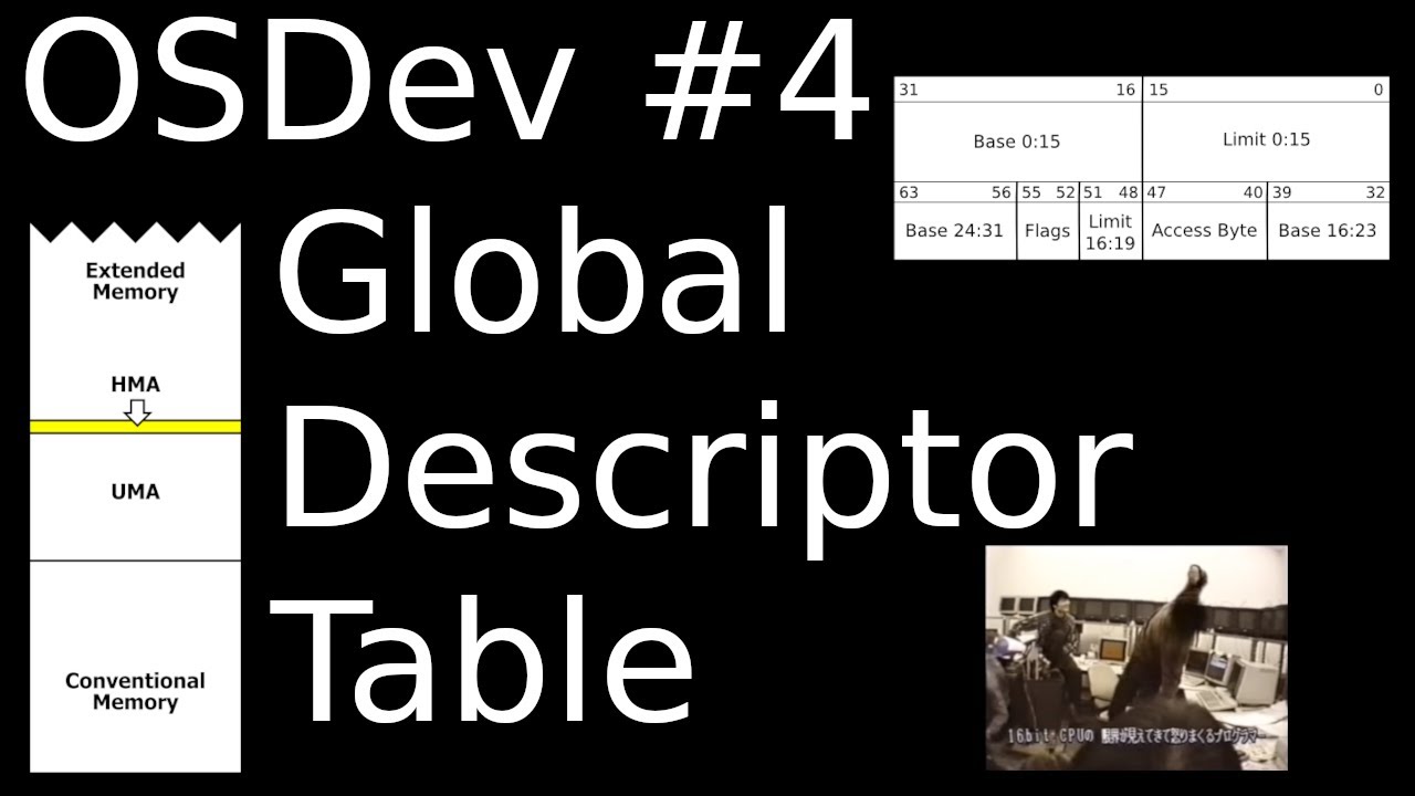
Transitioning from 16-bit Real Mode to 32-bit Protected Mode, including disabling BIOS interrupts and setting up the Global Descriptor Table (GDT).
Writing a multi-stage bootloader that loads a simple C-based kernel into memory and transfers execution control.
Direct memory-mapped I/O, such as writing characters directly to the VGA text mode frame buffer at address 0xB8000.
7.3K views205likes8:01Original Release: 2023-08-27
in the last video we saw how we could set up a really simple bootloader that basically just booted and halted the system in this video we're going to extend that concept further to actually print a message onto the screen when the operating system boots this will allow us to get an understanding of how we interact with the BIOS to be able to print messages onto the screen which is a relatively similar process to interacting with Linux in the sense that we're going to use interrupts however the interrupts are different and the way that we set them up is also going to be a little different so we're going to see that process here as we're working on printing a value out onto the screen so the very first thing that we need to do is in our main we actually have to set up our program so we have our registers sort of set up and initialized to a consistent State because we don't really know what state our program is going to be in when we first boot so we're just going to get everything set up the way it needs to be the way that we do that is we're going to move into ax the value 0. so we're going to initialize basically the ax register to zero and we're going to use that value to reset a few other important registers those registers are going to be the DS register the es register and the SS register now we haven't seen these registers so far as we've discussed x86 programming basically the DS register is going to keep track of the start address of the data segment the es register sets the start point of the extra segment and the SS register sets the start address of the stock we initialize these all to zero to be able to get a consistent starting point for everything and the last thing that we really need to initialize here is we need to move into the stack pointer the start address of our application 0x7c00 we do this because the stock grows downwards so what we're doing is we're basically starting the stock just after our actual application code so we can continue to go downwards from that point so that gives us a lot of space to actually grow on the stack which is going to allow us to work with the stock in a much more effective way so with that I'll initialize we can start on our actual program for printing values to the screen and we're going to put this just below halt is probably an okay place for it you could put it above the main but if you do that you have to jump to main before the program actually starts right so you have to basically jump to main as the first line of code if you have print above it that way it doesn't like jump right into print and start trying to print things to the screen so generally I like to put my functions below the main so that everything starts into Main and then we can jump around as needed now for the print function what we're going to do is we're going to provide a few different values to this function so first thing we want to do is preserve the values that we're going to be working with inside of this function so we're going to work with the SI register the ax register and the BX register so we're going to push those all onto our stack so we can preserve their values during the application so we'll push on SI ax and BX and then we're going to set up a loop inside of here what this Loop is going to do is it's going to load data from our string into memory and then it's going to print out the value basically character by character so to understand how that's done let's actually Define the string that we want to print I'm going to call this the OS boot message you can do it whatever you'd like it's going to be defined as a DB and it's going to have a message inside of it and you can put any message inside of here that you would like General output Ros has booted I'm going to put 0x0d 0x0a these are new line characters so these will indicate that a new line should be printed as well then we're going to put a zero and the zero is basically just a value that indicates where the end of this string is now when we actually go and call this function in main what we're going to do is we're going to move into the SI register the OS boot message address so that's the way that we're setting this up and then here we could just call Print so basically we put the message into the SI register and then we call the print function when we come into the print function it'll be preserve SI ax and BX it's we're going to be overriding them in the function itself and then here what we're going to do is we're going to do a few different instructions to load our string character by character and print it onto the screen so the first thing is going to be to do an LOD SB what this does is it loads a single byte from the current location specified in si so a single byte is going to give us a single character of our string and that's what we're going to generally get from this instruction so this gets us a single character and it places that character inside of the AL register for us now what we want to do is we want to check to see what's the value that was loaded equal to zero because if it was that would tell us that we're at the end of the string and that we should stop printing the easiest way to do that is just to or Al with itself I did do a jump zero to done print so basically what this is going to do is this or instruction will set the flags for the instruction if the zero flag is set it would mean that Al must have been zero since if we or zero with itself we get zero in all other cases we wouldn't generally get that so this is what we're going to do to do this check so if we do get zero we'll jump to a label called done print uh done print I'll just Define all the way down here and here what we're going to do is we're just going to pop off the registers that we preserved that the ax BX and Si and then we're just going to return so that's where our return happens now if it isn't equal to zero we're not going to jump what we're going to do instead is we're going to do an interrupt the interrupt that we're going to do is actually going to be a bios interrupt and that bios interrupt is going to be set as follows we're going to move into ah the value 0x 0e this value here represents printing a character to the screen so this is the code used to print a character to the screen we're going to move into BH the value of 0. this is representing the page number as an argument you don't need to worry about the page number in this particular application basically what this is used for is it's used for cases where you have maybe multiple monitors and you want to write to a monitor that's not currently visible you can change this value to access different pages of memory since we're in the main page of memory as in the monitor that's being displayed we can set this as zero for our purposes and then the interrupt that we're looking for is 0x10 0x10 is called a video interrupt so this is going to do a video interrupt and what is going to happen is the BIOS is going to take a look at ah to determine what to do H being set to 0 x 0 e is going to tell it that it needs to print a character the character that it needs to print is the value in Al so it's going to take that value in Al it's going to print it onto the screen and then it's going to continue on now to get this to continue running we're just going to jump to print Loop so we keep looping through so what's going to happen is it's going to load a character it's going to check if it's zero if it's zero it goes to done print which Returns the function otherwise we set up the system call so we say we want to print a character we want to print it on the main screen of the computer and then we actually do the interrupt which would print the character we then go back to the top the top is then going to load the next character and we're going to continue that process until we reach the zero that's at the end of our string and then we are done and with this I think we should have everything all together that we need to get this print actually up and running so let's take a look and see what happens we're going to come into here and we're going to do our make to build our actual image I'm going to boot that image and see what happens do you see that now it shows Ros has booted so it actually does print the message that we're looking to print and with that you don't understand the basics of interacting with bios this is something that we're going to do pretty frequently as we're starting to write something like a bootloader so this gives you a bit more of an intuition around working with bios and also some of the other interrupts that exist because we only really saw one type of interrupt when we were working with x86 that was the 0x80 interrupt and the e0x10 is just another example of an interrupt we have for a different kind of scenario so with that you now have a really basic setup for being able to print a message onto the screen using bios so thanks so much for watching and I'll see you in the next video
Up Next
7:14
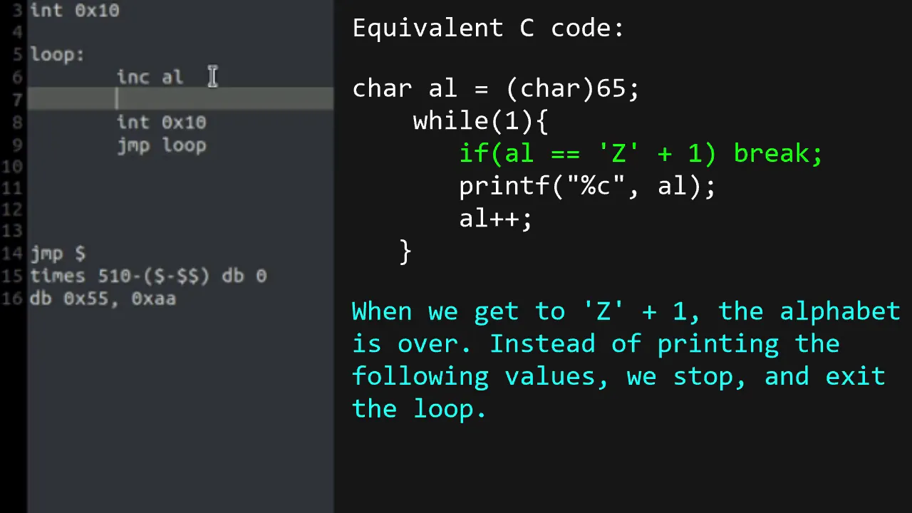
Building an OS: BIOS Interrupts and Conditional Jumps
@DaedalusCommunity
181.5K views•2020-08-30

87:26
Introduction to Secure Multiparty Computation with Yehuda Lindell
@fhe_org
7.7K views•2021-02-04

45:08
Building an IDT for x86 Operating Systems: Interrupt Setup
@olivestemlearning
7.6K views•2023-10-27
19:25
Enigma Machine Mechanics: WWII Encryption Explained
@JaredOwen
13.2M views•2021-12-11
Related Study Plans & Knowledge Roadmaps
Structured learning paths in Computer Science
computer-science
Container Runtimes: Namespaces, Cgroups & Go
01Linux Systems & Go Programming Foundations
02The Core of Isolation: Chroot and Filesystems
03Linux Namespaces: Process Isolation
+ 3 more learning modules
32h6 modules
Explore Roadmap
computer-science
Building a CHIP-8 Emulator: Rust & CPU Basics
01Computer Architecture Foundations (Bits & Bytes)
02Rust Programming for Systems Development
03CHIP-8 Virtual Hardware Specifications
+ 2 more learning modules
32h5 modules
Explore Roadmap
computer-science
Building BitTorrent: Go, P2P & Concurrency
01Go Fundamentals & Concurrency
02Networking Foundations & P2P Architecture
03Bencode Parsing & Torrent Metadata
+ 3 more learning modules
26h6 modules
Explore Roadmap
computer-science
Actor Models (C++ Concurrency & Lock-Free)
01C++ Multi-Threading Foundations
02Thread Pools and Task Scheduling
03Atomics and Lock-Free Queue Design
+ 3 more learning modules
45h6 modules
Explore Roadmap