















![Kłopotliwe ciepło [RS Elektronika] # 25](https://i.ytimg.com/vi_webp/ko9xLmW0yn4/maxresdefault.webp)







This video demonstrates how to build a USB charger that can convert 6V-24V power sources (like car batteries or moped batteries) into the 5V required for charging smartphones. The project compares two voltage regulator approaches: a simple linear regulator (LM7805) which is easy to build but inefficient (around 42.5% efficiency at 12V input) and generates significant heat, versus a switching regulator (LM2576) which achieves approximately 83% efficiency by rapidly switching the input voltage on and off. The switching regulator design requires only four external components (Schottky diode, coil, and two electrolytic capacitors) and can deliver 600mA output current, making it suitable for charging phones, tablets, and other USB devices from various voltage sources.
Build a USB Phone Charger for Any 6-24V Battery: DIY Regulator Tutorial
Added:[Music] You're on a trip with your buddies in the middle of nowhere. Using your smartphone to find the right way would be the best idea, but as always, that god damn batteries empty again. Talking about progressive technology. Your fellows can't help you either. With no USB socket inside, you're pretty much screwed. The only thing that comes to their minds are two power sources. A 6V DC battery of a moat and the always available 12vt DC battery of a car.
But you are prepared for such situations. In this video, I'm going to show you how to use those batteries to charge your phone with a simple and easy to build USB charger.
[Music] First of all, we're going to need a USB port. I desoldered one from this old USB hub I had laying around. Just desolder the four pins on the front and afterwards the two pins on the back which hold the port in place. You have to use some force to get it out, but eventually you'll make it.
For testing purposes, I soldered one wire to the ground pin on the right and another wire to the 5V pin on the left.
Afterwards, we have to short the data pins in the middle using solder or short piece of wire. The phone is going to charge the fastest with the pins shorted out.
The solution for stepping down voltages is a simple and easy to use linear voltage regulator, the LM7805.
You can get those for around a buck. The circuit only needs two external components and those are two one microfarad capacitor.
But be careful. I used electrolytic capacitors. Those are polarized components. That means it has a positive and a negative side. The negative side is always marked in this case with a line. And the negative side goes obviously to ground.
The IC has three pins input, ground, and output. Ground connects to the negative side of the caps and one positive side to input and the other to output. Should be pretty easy. After constructing the circuit on a breadboard, I hooked up the 6 volts of our battery and measured around 5 volts on the USB port. And in case you didn't know, USB works with 5 volts.
So, let's measure the current which is flowing. The phone does charge, but we are only getting around 100 milliamps, which isn't much. The problem is the IC operating voltage starts with 7 volts.
So this scenario isn't unusual, but at least it charges a bit and it would be enough for an emergency call.
Another huge problem appeared when I tried hooking up to 12 VTs. It charges much faster, but the IC got really hot and I thought it might blow up. I tried using heavier loads to show you one blowing up, but then I realized it has a thermal overload protection. Good thinking producer. The problem is the efficiency. Our input power is 12 V multiplied by 0.33 amps which is around 4 W. Our output power is 5 V multiplied by 0.33 amps which is around 1.7 W. The efficiency is output power divided by input power multiplied by 100%. So around 42.5%.
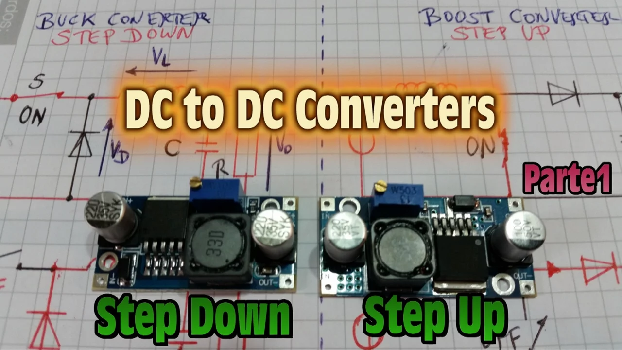
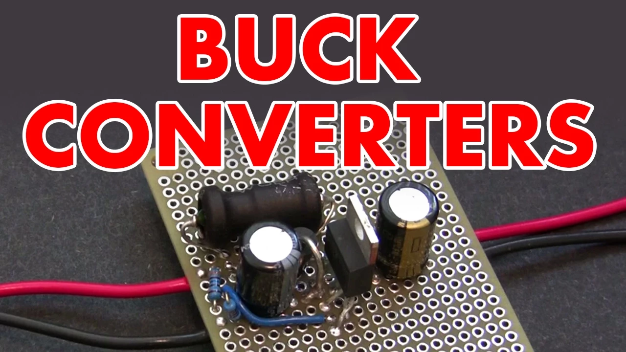
The higher the input wtage, the lower the efficiency will be and more heat will be produced. Remember, when you want much power from your regulator, the linear kind is The solution, a switching voltage regulator. By switching on and off the input voltage really fast, it creates a somewhat stable adjustable output voltage. In our case, 5 volts. Complicated to explain in only one video. It only requires four external ports. one shotkey diode, a coil and two electrolytic capacitors.
The diode let current flow in only one way. The other way around the resistance is ideally infinite. So look out during connecting. The LM2576 has five pins and must be connected as shown in the schematic. And of course you can download all schematics and the part list link is in description.
After wiring up the breadboard and hooking it up to 6 volts, it produces 5 volts as well. I also had the low current flowing with 6 volts because operating voltage starts again at 7 volts. But it charged with 600 milliamps using 12 Vts and it only took 300 milliamps as an input current which means we have reached an efficiency of 83% and that's definitely good enough.
You can use this barebone version, but I decided to put everything together in a case. This little plastic case comes with a PCB which fits inside and can be secured with screws. Perfect for the project.
I also used two binding posts, one small main DC switch, one green status LED, one stepping switch, and a knob for this switch. I drilled holes and cut the plastic to fit all my components inside.
After mounting the binary poles and the stepping switch, I heated up the hot glue gun, maker's best friend. I used hot glue to secure the status LED and the little main switch. But be careful.
Don't cover your leads in hot glue. We have to solder wires to them later. The coil is so big, it won't fit on the PCB.
So, I solder two wires to its leads and use shrinking tube to protect the connections. Afterwards, it got glued in the case.
Now, we have to connect those components with wires. The negative binary pole goes directly to ground on the PCB. The positive binary pole connects to the main DC switch. From there, we go to the middle of the stepping switch. We have three different switch modes. One is going to be the LM2576 and two, the LM7805.
Position three will be exposed in our video. solder wires to the switch position one and two which will be later connected to the inputs of the regulator on the PCB. The USB port's positive pin will be connected to the resistor of the LED and from the resistor to the positive lead of the LED. The ground pin of the USB port will also be connected to the negative lead of the LED. The plastic case of the LED is not completely round on the negative side for your help. Lastly, the USB ports positive and negative pins will get a wire for later connecting to the PCB. We are almost done. Now, we have to solder our components onto the PCB. Always look carefully at the schematic and check your connections twice when you think you're finished.
[Music] The last step would be to connect the ports in the case with the correct component leads on the PCB. And if the gadget is not working the first time, don't give up. Check your connections and look for shorts on the PCB.
And it's done. Your new gadget can not only charge your phone with your car battery, it can also charge your tablet or any USB device. It does also work with a variety of voltages from 6V to 24 volts. Don't forget to check out my last video about synchronizing sound to light. If you have ideas for the next electronics project, please leave a comment. And please like and share this video and subscribe to my new channel.
See you next time.
Up Next

AC to DC Rectification: Half-Wave vs Full-Wave Explained
@EugeneKhutoryansky
386.9K views•2015-08-24

Ultrasonic Transducers: Resonant Frequency Measurement and Horn Design
@imajeenyus42
229.9K views•2017-02-22
Understanding Servo Motors: How They Work & How to Use Them
@greatscottlab
977K views•2016-10-23

How a Student's Question Saved a NYC Skyscraper from Collapse
@veritasium
22.8M views•2025-04-26
Related Study Plans & Knowledge Roadmaps
Structured learning paths in Engineering