




















![[Sensores Arduino] Sensor Detector de Sonido/ Sensor Ultrasónico/ Sensor PIR ~ Moshiko](https://i.ytimg.com/vi/pCdM55saJlM/maxresdefault.jpg)




![[RELAY] 7 FORMAS de ARRUINAR tus DISEÑOS](https://i.ytimg.com/vi/IlfEYTcdfHE/maxresdefault.jpg)
![Clase Día 8 Programación de llaves e Inmovilizadores [Maratón Virtual]](https://i.ytimg.com/vi/nDbrhgu7g4o/maxresdefault.jpg)






This video demonstrates how to control electronic peripherals like LEDs, motors, and servos through GPIO pins of microcontrollers (Arduino Uno) and single-board computers (Raspberry Pi), covering essential concepts including voltage levels (5V for Arduino, 3.3V for Raspberry Pi), current limits (40mA for Arduino, 2mA for Raspberry Pi), current sinking and sourcing, pulse-width modulation for brightness control, signal amplification using transistors and operational amplifiers, and inter-computer communication through voltage dividers.
Physical Computing: Controlling LEDs, Motors, and Servos via GPIOs
Added:Basic electrical concepts including Voltage, Current, Resistance, and Ohm's Law to prevent damaging components.
Familiarity with foundational programming logic (loops, conditionals, and variables) in C++ (Arduino) or Python (Raspberry Pi).
Understanding the difference between analog and digital signals, and how GPIO pins function as inputs or outputs.
How to read basic circuit schematics and use a solderless breadboard for prototyping physical circuits.
Advanced Pulse Width Modulation (PWM) techniques for precise speed control of DC motors and dimming of LEDs.
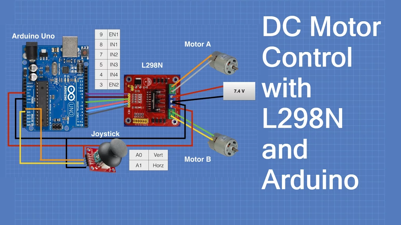
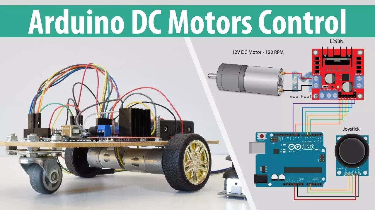
Utilizing H-Bridge integrated circuits (like the L298N) to safely control both the direction and speed of DC motors.
Integrating sensors (e.g., ultrasonic, temperature, motion) to create closed-loop, reactive systems where inputs directly trigger outputs.
Designing isolated, external power delivery systems to separate high-current inductive loads (motors/relays) from sensitive logic circuits.
Applying these control mechanisms to build complex systems like autonomous wheeled robotics, CNC machines, or IoT home automation actuators.
64.6K views740likes53:24Original Release: 2014-09-14
In this video I would like to explain how to amplify digital signals, so that you can control homebuilt peripherals by computers or microcontrollers.
Furthermore simple input functionalities are treated.
The control units I am using are an Arduino Uno microcontroller and a Raspberry Pi single board computer.
Both computing machines have digital input/output pins that can be used to control peripherals.
Before connecting a device to a pin you must consider the electrical properties of the ports!
The Arduino Uno operates with a pin voltage of 5V, while the voltage at the pins of the Raspberry Pi must be kept below 3.3V.
First let's have a look at the output mode of the pins.
In this mode, a single pin can be turned "on" or "off".
When turned "off", the voltage at the Raspberry Pi is 0V......while a low voltage of 0.1V can be detected at the pin of the Arduino.
The voltage is detected between pin and ground, which is the negative terminal of the supply voltage.
If the pin is turned "on" by software, we can detect 4.97 thus almost 5V at the Arduino......and 3.32V at the Raspberry Pi.
Besides the output voltage, the maximum current provided by a single pin is important!
It must be kept below 40mA at the Arduino and below 2mA at the Raspberry Pi.
Accordingly no device drawing a higher current should be connected to a pin, because the microcontroller or the computer will be destroyed immediately!
Using Ohm's law we can calculate the minimal resistance of a device drawing that maximum current.
For the Arduino we get 125 Ohms and for the Raspberry Pi 1650 Ohms for the minimal resistance of a load.
To avoid going to the physical limits, the resistance should never drop below 150 Ohms respectively 2 Kiloohms.
For the maximum electric power we get 200mW respectively 6.6mW.
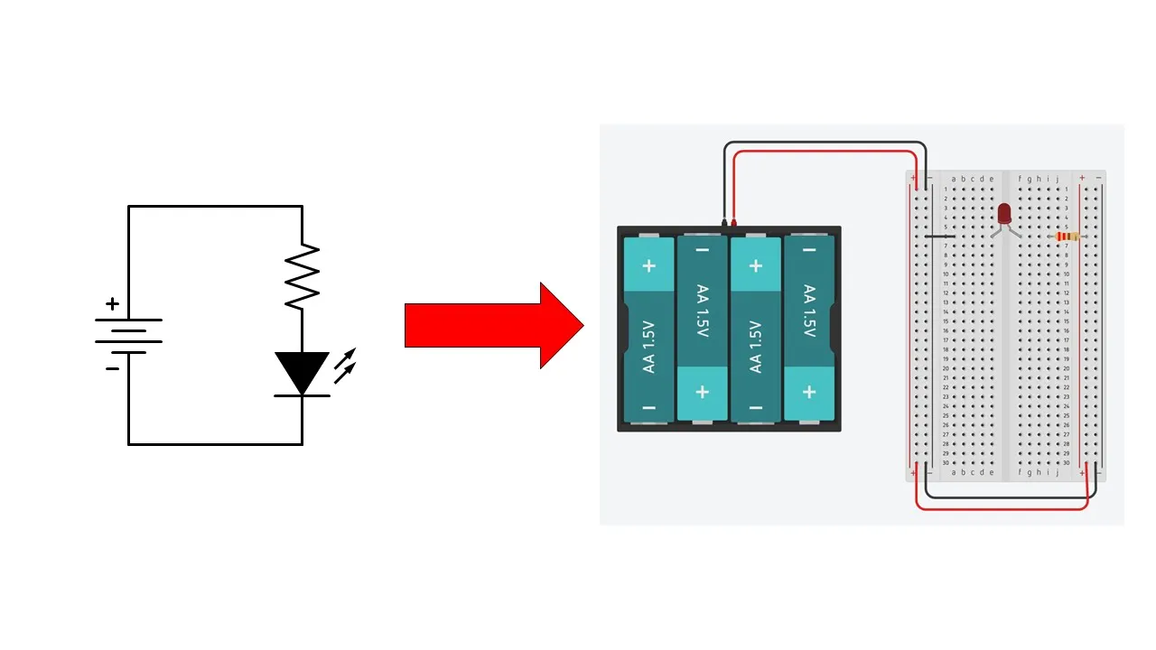
An LED is a simple load for our experiments.
You should never connect such a device directly to a pin, because the resistance of an LED is very low in operation mode.
In order to limit the current we need a series resistor with a value of 180 Ohms for the Arduino and 2 Kiloohms for the Raspberry Pi.
Furthermore the polarity of an LED has to be considered: To get an LED lighted up, it must be connected with correct polarity to the supply voltage.
The negative terminal of these LEDs is marked by a flat area at their sockets.
The LED-resistor combination is used as load in our first experiments.
That load can be connected either between the output pin and the positive terminal of the supply voltage or between the pin and the negative terminal.
Both, Arduino and Raspberry Pi have special pins providing +5V or +3.3V.
Those pins should be used as positive terminals for our first experiments.
As mentioned before, the voltage attached to a pin should never exceed the specified maximum!
Because of the importance of the voltage, the cables are usually marked by color codes.
At computer power supplies, orange colored cables are used for +3.3V, red cables for +5V and yellow cables for +12V.
The negative terminal, also named ground, is the reference potential and so the most important cable.
It is always marked as black cable.
All pins are initially turned off, thus there are (almost) zero volts between ground and each of the pins.
As you can see, the LED connected between the positive terminal and pin number 4 is lighted up.
We can detect a potential of 4.66V, thus almost 5V across the load.
At the Raspberry Pi we get a reading of 3.29V between the positive terminal and the pin being turned "off" - this load is also turned on.
The light emitted by the LED is weaker than that at the Arduino, remember that the current running through the device is below 2mA compared to 40mA at the Arduino.
The positive current is running from the positive terminal through the load into the digital pin - it is called "sink current", the pin operates as current sink.
The voltage across the loads connected between the negative terminal and one of the pins is 0V......by what those LEDs are turned off.
When turning all pins "on" by software, the situation changes: Now, there is a potential of 0V across a load connected between a pin and the positive terminal - the LED is turned off.
In contrast, we can detect a potential of 4.61V......respectively 3.29V across the loads connected between an output pin and ground.
The positive current is running out of the pins through the loads and into the negative terminal.
The output pin operates as current source, thus a "source current" is coming out of the pin.
As mentioned before, an LED is lighted up only when operated with correct polarity.
This circuit is composed of two LEDs with different polarity and a series resistor.
That special load is attached between two output pins.
None of the LEDs is lighted up while both pins are turned off - the potential across the load is 0V.
The situation doesn't change when turning both pins "on" - the potential across the load is still 0V.
Now, pin number 10 is turned "off", while pin number 0 is still turned "on".
A positive current runs out of pin 0 through the load into pin number 10 - the green LED is lighted up.
If pin 0 is turned "off" while number 10 is turned "on", a "source current" is coming out of pin number 10 running through the load and finally as "sink current" into pin number 0.
Now, the red LED is lighted up.
The current running from one pin to another has also to be kept below the limit of 40mA at the Arduino respectively 2mA at the Raspberry Pi!
Avoid shorting two pins as this will destroy your tiny computer inevitably!
The type of wiring used in this video is clear, but caused by the many blank cables there is a high danger of shorting a circuit.
In practice you should solder all devices on a board or use a breadboard for experimental circuits!
Use kink protections for cabling running to your board......and ribbon cable connectors instead of single cables.
Whenever detachable connections are needed, use jacks with a reverse polarity protection.
The pins will now be used as current source, thus loads are connected between pin and ground.
If multiple pins are used to control multiple LEDs, all circuits originate from one of the output pins, running through an LED and a resistor and finally they converge at the ground cable.
Each LED can be turned "on" or "off" by software.
When turning an LED on and of at a fast pace, your eye can't catch each switching procedure.
The LED is glowing weaker than the device to the left which is turned on permanently.
When reducing the turn on time in relation to the turn off time, the luminance is decreasing.
That method is called pulse-width modulation treated in one of my previous videos.
By doing some coding you can create light patterns.
The low luminosity of the LEDs connected to the Raspberry Pi is caused by the low electric power of just 6.6mW provided by the Pi in comparison to 200mW at the Arduino.
So next we will learn how to amplify the electric power using transistors.
Basically there are two types of transistors: Bipolar Junction Transistors and Field-effect transistors.
I would like to demonstrate the use of field-effect types, since there is no current needed to control those devices which simplifies the calculation of an amplifying stage.
A field-effect transistor has three pins, named source, gate and drain.
Have a look at the datasheet of your transistor to find out what pin belongs to what functionality since your circuit won't operate correctly if you swap the pins!
For the first circuits I am using an n-channel MOSFET type 2N7000.
The source pin of the transistor is connected directly to ground while the drain pin is connected to the positive terminal through the LED and the series resistor.
The Arduino as well as the Raspberry Pi have two different positive terminals: One with a potential of 3.3V and one with a potential of 5V between plus and ground.
For safety reasons I am using the lower potential of just 3.3V.
The third pin of the transistor is connected to the output pin.
In principle the gate could be connected directly to the output of your computer, but when creating circuits, failures happen - I know what I am talking about... For safety reasons I am using a 16 kiloohms resistor between gate and output pin to limit the current in case something goes wrong.
Another device used for safety is the pull-down resistor with a value ranging from 200 kiloohms to one megaohm between gate and source of the transistor.
That pulldown resistor turns the field-effect transistor "off" whenever the circuit gets disconnected from the output pin of your computer.
There are two circuits, named input and output circuit: The input circuit starts at the output pin running through the two resistors to ground; the output circuit starts at the 3.3V terminal running through the resistor, the LED and the transistor to ground.
The current running through the input circuit is limited by the two resistors switched in series and it is totally independent from the current running through the output circuit.
We get 3.3 respectively 5µA for the input circuit and so for the source current coming out of the pins.
Now, the current running through the output circuit is no longer limited by the electric properties of the output pins but only by those of the transistor respectively the LED.
According to the datasheets the maximum current of the LED should not exceed 60mA while that of the transistor is 200mA.
Thus the LED sets the limit.
The series resistor can be reduced to 100 Ohms, by what the LED is driven by higher electric power.
If the pin is turned off, there is a voltage drop of 0V between ground and gate of the transistor by what that device is turned "off", too.
The resistance of the source drain line is some megaohms, thus no current is running through the LED.
When turning the pins "on", we get 3.21V at the Raspberry Pi......and 4.80V at the pin of the Arduino.
Both transistors are turned "on" by the gate voltage so that the resistance of the source-drain line drops to just some ohms, thus almost the maximum current runs through the LEDs.
Transistors can also be switched at a fast pace, thus the luminosity can be controlled by pulse-width modulation.
So an n-channel field-effect transistor is turned on by a positive voltage between source and gate.
But what potential is needed to turn on the device reliably?
Well, that depends on the used type of transistor.
In the data sheet the potential is denoted as "Gate Threshold Voltage" and we get typically 2.1V for the 2N7000.
Caused by production issues, the threshold voltage can vary between a minimum of 0.8V and a maximum of 3.0V.
The 3.3V provided by the Raspberry Pi as well as the 5V of the Arduino are are indeed sufficient to turn the transistor fully "on".
Further parameters to be considered are the maximum drain current, listed as 200mA and the maximum drain-source voltage, listed as 60V.
Now that we know that our circuits work properly, we can connect the positive terminals to the 5V pins.
Caused by the higher voltage, we get a higher current through the output circuit, thus the series resistor has to be considered: We need a minimal resistance of 84 Ohms to avoid damaging the LED, thus the 100 Ohms resistor is sufficiently high.
The LEDs are shining brighter.
The tiny fan from an old computer draws a current of less than 65mA at a DC voltage of 5V, by what the LED/resistor combination can be replaced by this electric motor.
Now, approximately 65mA are running through the drain-source line of the transistor, but still only 3.3 respectively 5µA through the pins.
Note, that there is also a current limit for the 5V pins - it should not exceed 200mA at the Raspberry Pi......and 400mA at the Arduino Uno!
The fan can be operated with 12V, but weather the Arduino nor the Raspberry Pi provide that voltage, thus we need an external power supply like a battery.
When connecting the fan directly to the battery, a current of 125mA is drawn by the load which is below the limit of the 2N7000.
In order to connect the battery to the computer, the negative terminal of the battery has to be attached directly to the negative terminal of the Arduino respectively the Raspberry Pi.
Don't connect the positive terminal of the battery to the positive terminal of the Arduino or the Raspberry Pi or to any other pin of the computers since the high voltage will inevitably destroy your computing machines!
So ensure that it is the negative terminal of the battery that is connected to the ground pin of your board!
Use black cables for this important line.
The drain pin of the transistor is connected indirectly to the positive terminal of the battery through the fan.
When turning the pin "on", the fan is running with 12V, spinning with maximum revolution speed.
You can use pulse-width modulation to lower that speed.
Next I would like to control a really strong electric motor which is a windscreen wiper of a passenger car.
The operating voltage is 12V and we can read a current of 12A when connecting the device directly to the battery.
We need a different type of transistor than the 2N7000 to switch that high current.
I am using an n-type field-effect transistor type IRLZ24N with a maximum continuous drain current of 13A.
According to the datasheet, the source gate threshold voltage is 2V, thus the device can be controlled directly by the Arduino as well as the Raspberry Pi.
Because of the fact that we are near the maximum current of the transistor, a higher gate voltage is better!
The maximum continuous current of 13A is listed at a source-gate voltage of 10V.
How can we get that voltage at the gate of the power transistor?
Let's go back to the circuit composed of the small signal transistor with the LED-resistor combination used as load and let's detect the voltage between source and drain - in the state "on" as well as in the state "off".
If the pin is turned "on", there are almost 3.3V at the gate and between source and drain of the transistor the reading is almost 0V.
If the pin is turned "off", the gate voltage is 0V and the reading between source and drain is 10.81V.
With a 12 kiloohms resistor in parallel to the LED we get 12.48V which is very close to the output voltage of the battery.
The voltage across the small signal transistor is either 0 or 12V.
The gate of the power transistor hast to be connected to the drain of the small signal transistor.
The wiper motor is connected between drain of the power transistor and the positive terminal of the battery.
Drain of the small signal transistor is also connected to the positive terminal of the battery through the LED and the 1 kiloohm resistor.
The negative terminal of the battery is joined with the ground pin of the computer directly using a black cable.
Whenever the potential at the output pin is 0V, there are 12V at the gate of the power transistor by what this device is turned "on" and the motor is spinning with maximum power.
If the output pin is turned "on" we get 3.3V at the gate of the small signal transistor, turning this device "on".
The potential at the gate of the power transistor is 0V by what this device is turned "off" - the motor stops spinning.
The Raspberry Pi can control the motor, but the pin has to be turned off in order to turn the motor on and vice versa - the switching behavior is "inverted".
That issue can be fixed by software but there is one problem left: During boot process, this pin is turned "off", thus the motor is spinning until the software used to control the pins is loaded and the pin is turned "on" in order to turn the motor off.
With another small signal transistor in that chain, the switching behavior is inverted for a second time: Whenever the pin of the Raspberry Pi is turned "off", the first small signal transistor is turned "off", too.
For this reason there is a voltage drop of 12V at the gate of the second small signal transistor turning this device "on".
Thereby the potential at the gate of the power transistor is 0V by what this device is turned "off" same as the pin of the Raspberry Pi.
When the pin is turned "on", the power transistor is also turned on through the second small signal transistor, thus the motor starts spinning which is the normal switching behavior.
As you might have noticed, the power transistor fused during operation.
13A are the limit for the IRLZ24N and a heatsink is needed to avoid the destruction of the device by the dissipated electric power.
The small signal transistor can be replaced by an operational amplifier: Those devices have an inverting and a non-inverting input as well as an output - additionally there are two terminals for the supply voltage.
The output voltage is 0V whenever the potential at the inverting input is higher than that of the non-inverting input.
Vice versa, if the potential at the non-inverting input exceeds that of the inverting input, the output signal equals the positive supply voltage which is 12V.
A fixed potential of approximately 2.5V is applied to the inverting input using a voltage divider composed of a 100 and a 27 kiloohms resistor.
The non-inverting input is attached to the pin of the Raspberry Pi.
Once more a 16 kiloohms resistor is for safety reasons - considering the nearby pins of the chip there is a high chance of creating shortings during soldering work!
The resistor between non-inverting input and ground is a pull-down resistor as used with the small signal transistors before.
If the pin is turned "off", there are 0V at the non-inverting input; in contrast there are 2.45V at the inverting input by what the output of the operational amplifier is on LOW level - we can read 0V.
If the pin is turned "on", we can read 3.12V at the non-inverting input which is higher than the potential at the inverting input.
Consequently we can read 11V at the output.
The output of the operational amplifier follows the non-inverting input - only the voltage level in the state "on" is 11V instead of just 3.1V at the input.
Using another type of operational amplifier, we get an output voltage of 12.28V which is closer to the supply voltage of 12.98V.
The voltage level is shifted from 3.3V at the output pin of the Raspberry Pi to 12V - from 5V to 12V at the pins of an Arduino.
The operational amplifier is used as "level shifter".
The output current of an operational amplifier is also limited: The maximum source current for the types used in this video is approximately 20mA.
The gate pin of the power field-effect transistor can be connected directly to the output of the operational amplifier, by what the motor is switched synchronously to the output pin of the computer.
The motor is spinning whenever the pin is turned "on" and it stops spinning if the output pin is turned "off".
The supply voltage of the operational amplifier is 12V by what the gate of the power transistor is driven by (nearly) those 12V.
You can use pulse-width modulation to reduce the revolution speed.
The operational amplifier can also be used to invert the signal of the output pin: In order to do this, the fixed voltage of approximately 2.5V is attached to the non-inverting input of the operational amplifier while the computer pin is connected to the inverting input.
If the computer pin is turned "off", the potential at the inverting input is lower than that of the non-inverting input, thus the output of the operational amplifier is on HIGH level which is almost 12V.
Vice versa the potential at the inverting input exceeds that of the non-inverting input if the computer pin is turned "on" - the output of the operational amplifier is on LOW-level, which is 0V.
The motor is spinning if the pin is turned "off".
The power transistor can be replaced by a relay.
Same as a transistor a relay has an input and an output circuit.
While both circuits are joined at the source pin of a transistor, there is no conductive connection between input and output in a relay.
The input circuit is made of an inductor.
If a voltage is applied to the coil, the armature is attracted by the electromagnet making contact between the middle and left metal plate of the output circuit at this type of relay.
The nominal voltage of the electromagnet has to be considered.
The coil voltage of this relay is 12V and a current of 32mA is drawn by the device.
Thus the input circuit of the relay circuit can't be driven directly by an output pin - a small signal transistor is needed to shift the voltage level to 12V and to provide a current of at least 32mA.
The coil of the relay is switched between the drain pin of the small signal transistor and the positive terminal of the battery.
If the pin is turned "on", the small signal transistor is also turned "on", thus a current is running through the coil.
The contacts of the output circuit approach and the motor connected to the relay starts turning.
When using two 12V batteries, there is no conductive path running from the motor to the computer.
The negative terminal of the second battery, driving the output circuit, is not connected to the negative terminal of the first battery or the computer.
The current running through the coil of the relay is drawn from the first battery and the negative terminal of that power source is still connected to the ground line of the computer.
As demonstrated in a previous video, you can cascade relays by what a current of more than 100A can be switched with a computer pin.
Here, the Raspberry Pi controls the transistor, the transistor the relay, the relay the magnet switch - which is a large relay - and finally the magnet switch turns on the strong electric motor.
Less than 6.6mW control more than 400W of electric power.
With two relays, each with a changeover switch, the polarity of an electric motor can be swapped.
If both pins are turned "on" or both are turned "off", the motor stops spinning.
If pin 1 is turned "on" while pin 2 is turned "off", the motor is spinning counterclockwise.
If pin 1 is turned "off" while pin 2 is turned "on", the motor is spinning clockwise.
The relays operate as an electromechanical h-bridge.
Swapping the polarity of a motor can also be done with transistors.
We need four power transistors: Two N-channel and two P-channel type field-effect transistors.
Two small signal transistors are needed to shift the voltage level from 3.3V to 5V - as demonstrated before.
The working principle of h-bridges has been treated in a previous video.
This motor of the tray of an old CD-drive is drawing a current of less than 100mA, thus the 5V power pin of the Raspberry Pi can be used as power supply.
Two pins are needed to control the h-bridge: If both pins are turned "off", the motor is also turned off.
If output pin 1 is turned "on" while pin 2 is turned "off", the motor is spinning clockwise.
In contrast the motor spins counterclockwise if output pin 1 is turned "off" and pin 2 is turned "on".
If both pins are turned "on", the motor stops spinning - the transistor h-bridge is operating identically to the previous circuit composed of relays.
In contrast to relays, transistors can be controlled by pulse-width modulation, thus the power delivered to the motor can be varied continuously.
But be careful!
At this very simple h-bridge, a high cross current is running through the legs of the circuit whenever a transistor pair is switched!
When using a high base frequency for the pulse-width signal, the power transistors might get destroyed!
In the video about servos I have demonstrated that a special pulse-width signal is used to control those devices.
There are thee cables coming out of a servo: Plus, ground and the cable for the control signal.
The ground cable, usually marked brown or black is connected to ground of the computer Plus is usually marked as red cable and it is connected to a voltage of 5 to 6V.
In theory, the 5V pin of the Raspberry Pi or the Arduino can be used to power a servo, but keep in mind that the current drawn by a standard servo exceeds 500mA under load, which is above the maximum current of those pins.
A single micro servo can indeed be powered by the 5V pin of the Arduino since the microcontroller allows currents up to 400mA.
The black or brown cable is connected to a ground pin of the Arduino, the red cable to the 5V pin.
The orange or white cable for the control signal runs to one of the pulse-width pins of the Arduino.
Since servos are very common devices, the Arduino as well as the Raspberry Pi provide software routines generating that special pulse-width signal.
An external supply voltage is needed to power the standard servo connected to the Raspberry Pi.
The negative terminal of the battery with a nominal voltage of 6V has to be connected to the ground pin of the computer and that of the servo as explained before.
The red cable of the servo is connected to the positive terminal of the battery.
Eventually a small signal transistor is needed as "level shifter" since some servos need 5V pulses at the signal cable - other types can indeed be controlled by 3.3V pulses.
As demonstrated before, the pulse-width signal is inverted by the level shifter, which must be compensated by software.
The angle of rotation is set by software.
Hacked servos can be used as compact geared motors - the HowTo is available in the video about servos.
The compact drive can rotate in either direction with different speeds.
In contrast to the h-bridge treated before, a single output pin is sufficient to set the rotational direction and the speed of the motor.
A GPIO can be set as output or input pin, which is why they are called "General Purpose Input Output".
As demonstrated, an output pin is suitable to control peripherals, but what are input pins good for?
An input pin hands a "0" to the software code whenever the potential is below a given threshold.
If the potential exceeds that threshold, a logic "1" is handed to the software.
Here, the state of the input pin is indicated by an LED connected to a second pin switched to output mode.
Whenever a logic "0" is indicated by software, the LED is turned off - otherwise it is turned "on".
When raising the input voltage slowly the Raspberry Pi indicates a logic "1" at a potential of 1.34V - the LED is turned on.
If the input voltage is lowered, a logic "0" is indicated as soon as the potential falls below 1.17V.
The threshold triggering a logic "1" with rising input voltage is higher......than the threshold needed be underrun for a logic "0" at falling input voltage.
That principle is called "hysteresis".
We get 2.49V at rising input voltage and 2.23V at falling input voltage for the Arduino Uno.
A DC voltage is never ideally constant - there has always ripple to be considered.
Without hysteresis, thus if both thresholds are identically and the input voltage is close to that threshold, the input state changes between "0" and "1" even with a tiny interference.
Thats demonstrated with a special input pin of the Arduino.
The threshold is set to 2.5V and the LED is permanently turned "on" and "off" even if the sliding contact of the potentiometer is not moved.
As said multiple times before, the voltage at a GPIO should not exceed 3.3V at the Raspberry Pi respectively 5V at the Arduino board!
A simple way of attaching the correct voltage to an input pin is using a switch or push button connected to two 16 kiloohms resistors.
One terminal of the switch is connected directly to ground of the computer, while the second terminal is connected to both resistors.
The second terminal of the first 16 kiloohms resistor is connected to +3.3V of the Raspberry Pi respectively to +5V of the Arduino.
The second terminal of the second resistor is connected to the GPIO.
If the switch is "open" there is a potential of (almost) 5V across the push button and so at the input pin, thus a logic "1" is detected.
If the pushbutton is closed, the reading at the input pin is 0V, thus a logic "0" is detected.
The state of the switch can be read by software.
We can read 3.2V at the opened switch connected to the input of the Raspberry Pi and 0V if the switch is closed.
The second 16 kiloohms resistor is for safety reasons: If the pin is accidentally switched to output mode and turned "on" while the switch is closed, a high current would run through the pin without that resistor, thus the computer would get destroyed immediately.
The resistor limits that current and saves your Raspberry or Arduino.
Error free software doesn't exist - so never forget to implement protective resistors!
An input pin of one computer can be used to detect the state of the output pi of a second computer: Here, an output pin of the Arduino is connected to an input pin of the Raspberry Pi.
There is no straight forward wiring, since the output voltage of the Arduino is 5V which would destroy the Raspberry Pi!
There is a voltage divider composed of two 200 kiloohms resistors between output pin of the Arduino and ground.
With the voltage divider the potential at the input pin of the Raspberry is reduced to just 2.5V which is sufficient to detect a HIGH signal.
Ground of Raspberry Pi and Arduino are joined directly through the black cable - make sure you choose the CORRECT pins before turning on the tiny computers!
If the pin of the Arduino is switched to output mode and the pin is turned "on", we can read 4.92V at that pin.
The voltage is halved by the voltage divider to just 2.46V which is sufficient to detect a HIGH signal at the Raspberry, whose pin is switched to input mode - the LED at the Pi is turned on.
That communication line can also be used in the opposite direction: Now, the pin of the Raspberry Pi is switched to output mode and that of the Arduino to input mode.
As demonstrated before, a potential above 2.5V is sufficient for the Arduino to detect a HIGH signal, by what the software reads a logic "1" turning the LED on.
Both computers can communicate using that wire.
If the Arduino receives 3 HIGH pulses, the servo is turned clockwise.
As soon as 5 pulses are received, the servo turns counterclockwise.
Communication can be established in both directions: Now the Arduino sends pulses to the Raspberry Pi, thus the fan is turned on.
6 pulses are stopping the motor.
Communication between computers is fascinating which is why there will be a subsequent video about this subject.
The Arduino has 6 analog input pins.
Those pins can be used to read the exact value of a potential instead of merely returning a "0" or "1" if the voltage is above or below a threshold.
The potential is returned as an integer value between 0 and 1023 - here the value is indicated as an LED bar.
Note that the voltage at an analog input must also be kept below 5V!
Simply connect a potentiometer between ground and the +5V pin.
The middle pin of the potentiometer is connected to the analog input pin of the Adruino - through a 16 kiloohms resistor for safety reasons.
Now, the position of the potentiometers sliding contact can be detected.
That position is converted into a pulse-width signal controlling a servo.
Now, the servo arm follows the movement of the potentiometer lever.
The reading of the analog input can be transmitted to the Raspberry Pi trough an USB interface - thus the servo is controlled indirectly.
The Arduino with the potentiometer operates as controller.
Now that you know how to handle one servo, you can use multiple devices: This robot arm is made of 6 servos.
The tiny robot arm connected to the Arduino is made of 5 potentiometers - that needed for opening or closing the hand is not implemented.
The movement of the tiny robot arm at the Arduino can be transmitted to a Raspberry Pi controlling the larger version through any distance.
Or you can use the Arduino to record motion sequences which can be recalled multiple times - a helpful thing in mass production.
As you can see, the precision of this robot arm and the mechanical power is really low, so it is not suitable for commercial use.
How to build really strong servos using a wiper motor and an Arduino Uno was demonstrated in the previous video.
So you can move something, literally.
This tiny robot is driven by a hacked servo while the steering is done by a normal servo.
the third servo turns the camera......and LEDs can be turned on when driving during night times.
You can control that tiny robot on my attic using a browser - try it out.
This rover is larger and the power comes from a 6V battery.
Inside the robot, an Arduino - without the Uno board - and a Raspberry Pi are working in team play.
Through an analog input, the battery voltage is recorded by the Arduino and the value is transmitted to the Raspberry Pi using three communication lines at the GPIOs.
The robot can disable itself if the battery voltage drops below a given threshold, preventing the battery from deep discharge.
There will be an extra video about this robot, demonstrating how to recharge the battery with photovoltaic cells.
Besides energy management, the analog inputs of the Arduino will be used to record sensor data of the environment - this rover will transmit more but only camera pictures to your browser.
As you can see, the vehicle has good off-road capabilities, thus the RoboSpatium can be extended to outdoor space.
Now that you know how to control powerful peripherals through your computer and how to read sensor data, the size of your robot depends only on your mechanical skills: This vehicle is 1.4 meters wide......4 meters long and has a weight of approximately 400kg.
The robot is driven by a 20000W combustion engine.
It can move remote controlled trough WLAN or autonomously - assuming there is sufficient sensor data available and you are an excellent coder.
...but never forget to implement an emergency-off functionality...
Up Next

29:25
DIY Analog Solar Tracker Circuit Without Microcontroller (LM324 Op-Amp Guide)
@LariFariYoutube
3.4K views•2024-01-14

30:32
Ultrasonic Transducers: Resonant Frequency Measurement and Horn Design
@imajeenyus42
229.9K views•2017-02-22
37:11
Stepper Motor Working Principles: Bipolar, Unipolar & More
@HomoFaciens
156.6K views•2015-07-29

33:39
How a Student's Question Saved a NYC Skyscraper from Collapse
@veritasium
22.8M views•2025-04-26
Related Study Plans & Knowledge Roadmaps
Structured learning paths in Engineering
engineering
Building Acoustic Levitators: Physics & Arduino
01The Physics of Sound and Standing Waves
02Piezoelectric Transducers and H-Bridge Drivers
03Arduino Programming: Generating 40 kHz Signals
+ 2 more learning modules
14h5 modules
Explore Roadmap
engineering
Building Peltier Cloud Chambers: Particle Tracks
01Cosmic Rays & Cloud Chamber Physics
02Thermoelectric Cooling (TEC) Fundamentals
03Custom Liquid-Cooling Loop Design
+ 2 more learning modules
18h5 modules
Explore Roadmap
engineering
Yagi-Uda Antennas: Modeling, Build & VNA Test
01Introduction to RF and Antenna Fundamentals
02Yagi-Uda Antenna Design Principles
03Antenna Modeling and Simulation in 4NEC2
+ 2 more learning modules
18h5 modules
Explore Roadmap
engineering
ECG Monitor Design: Op-Amps, Filters & Noise
01Electronics & Breadboard Basics
02Op-Amps and Instrumentation Amplifiers
03Bioelectricity and ECG Fundamentals
+ 2 more learning modules
18h5 modules
Explore Roadmap