

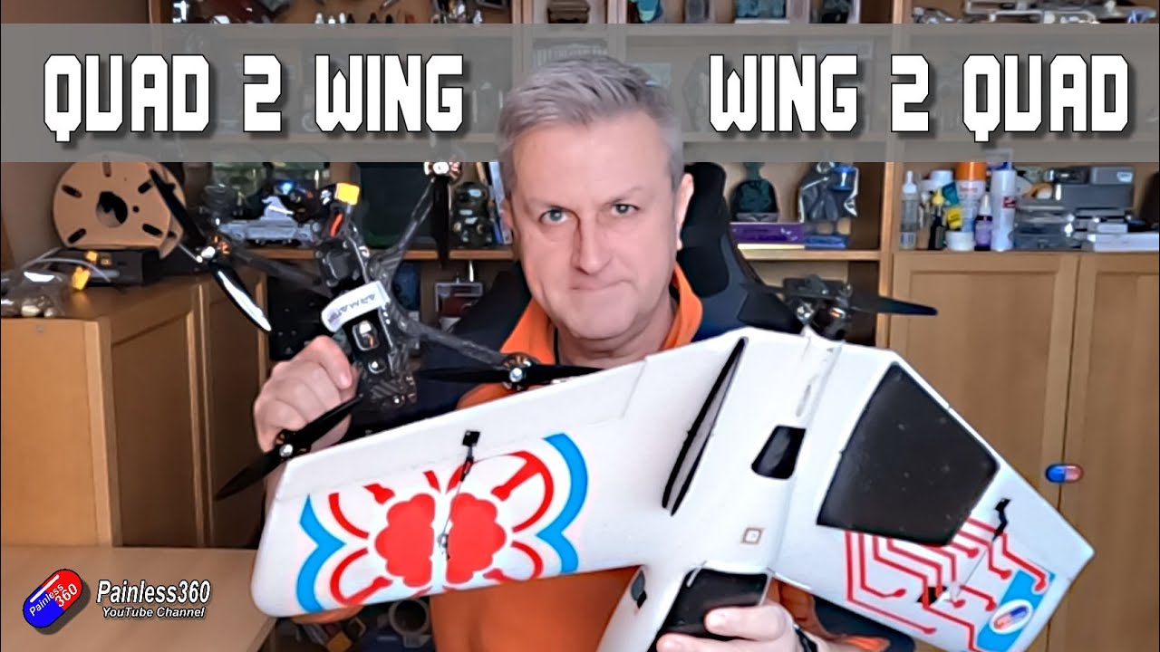











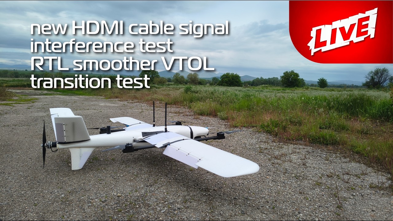


This tutorial demonstrates how to configure Arduplane for a T1 Ranger tiltrotor VTOL, covering essential steps including accelerometer and compass calibration, radio and servo output configuration, motor pin assignment, enabling quadplane and tiltrotor features (Q_ENABLED=1, Q_TILT_ENABLED=1, Q_TILT_TYPE=2, Q_TILT_MASK=3), adjusting tilt angles and endpoints, configuring power systems (ESC type, battery voltage limits), and setting transition parameters (tilt rates, transition speed, minimum altitude). The guide emphasizes testing control surfaces and tilt servos before first flight, and recommends using FBWA mode during transitions instead of ACRO or MANUAL modes to maintain motor stabilization.
ArduPilot Tiltrotor VTOL Setup Guide | T1 Ranger Configuration
Added:Basic navigation of ArduPilot ground control software (Mission Planner or QGroundControl), including firmware flashing and parameter modification.
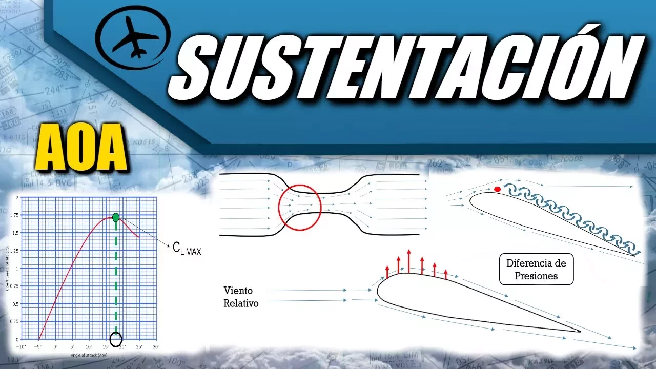
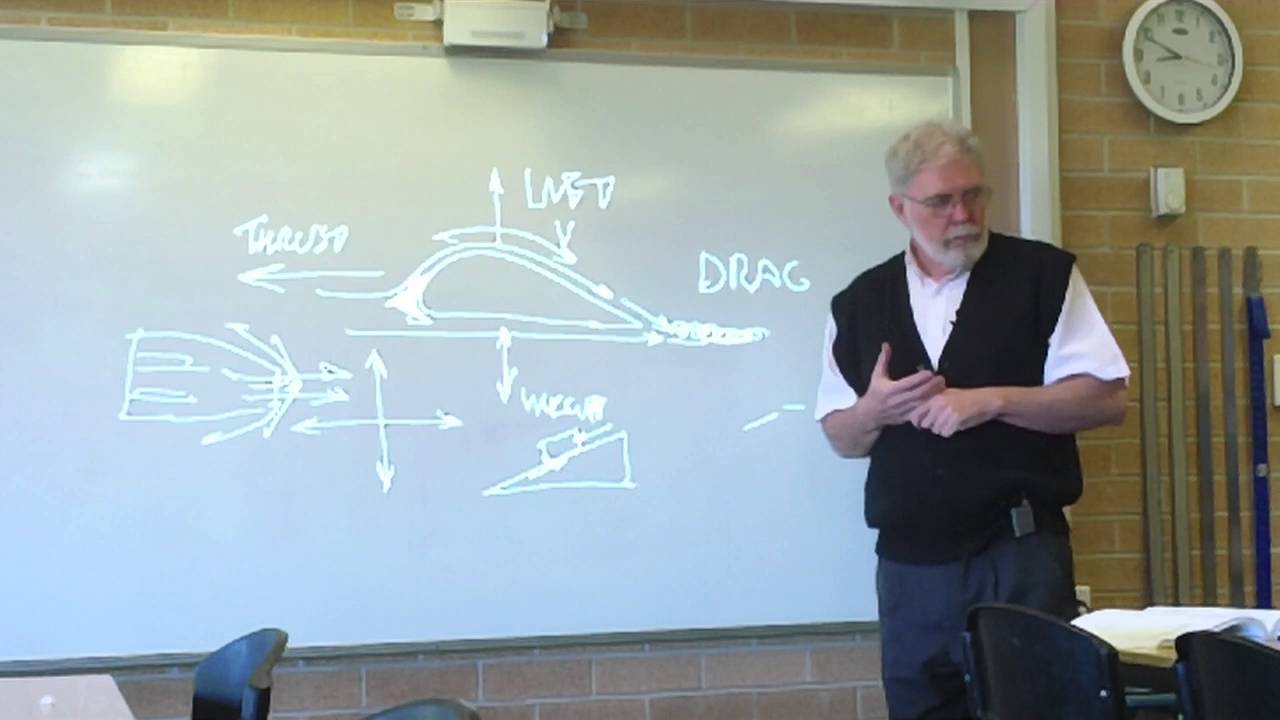
Fundamental aerodynamic concepts of both fixed-wing aircraft (lift, drag, thrust, gravity) and multirotor flight mechanics.
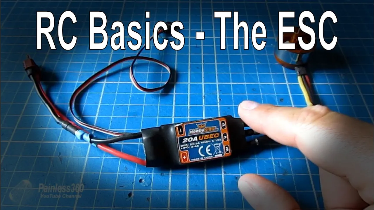
Working principles of RC electronics, specifically how ESCs, brushless motors, and servo motors operate and interface with a flight controller.
Standard ArduPilot sensor calibration procedures, including accelerometer, compass, and radio control (RC) calibration.
PID tuning and Autotune processes for both the multirotor (hover) and fixed-wing flight regimes in ArduPilot.
Conducting maiden flight tests and managing transition phases safely (front-transition and back-transition) in manual flight modes.
Advanced autonomous mission planning using VTOL-specific commands such as VTOL_TAKEOFF, VTOL_LAND, and transition waypoints.
Configuring advanced failsafes, geofencing, and emergency return-to-land (RTL) behaviors specific to tiltrotor airframes.
43.1K views738likes17:42Original Release: 2022-06-25
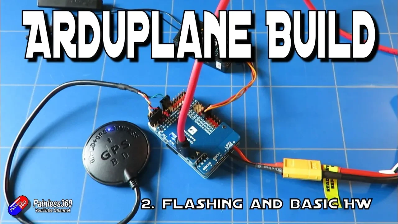
[music] Greetings again. I have made this AR the plane betal build guide for those who want to explore the belel capabilities of the plane. I won't discuss here how to flash the flight controller. So I'm assuming that you have already got that sorted.
Just like how other autopilot builds are configured, you begin with the accelerometer calibration.
This is a mandatory step in setting up an autopilot build. It starts by getting the data while the plane is level. Then you perform it again on all other axis.
It is important that you hold the plane still while calibrating on each axis.
After performing the 3D axle calibration, place the plane such that it will be level as if it is flying level in air. Then hit the calibrate level button. This will yield the trims for the flight controller.
Next is to calibrate the compass or magnetometer. It is important that when you do the compass calibration, you need to get the plane away from any other metallic objects.
Click on the start button and rotate the plane on all axis. You can find some information on the compass dancing and other videos uploaded online.
Following is the radio calibration which will set the mean and max PWM from your radio. It's recommended not to set any mix on your radio, but instead just need to set up at least eight channels and assign them to switches or pots.
Going to the servo output tab, you will see here the functions assigned to the corresponding output pins on your flight controller. By default, aeron, elevator, throttle, and rudder are assigned for the S1, S2, S3, and S4 pins, respectively.
Depending on how you connected the components, you may have to reassign the output functions. And in my case, I don't have anything connected to S1.
Thus, it has to be disabled.
However, the three motors are connected to the S2, S3, and S4 pins.
Furthermore, I have my aeron servos connected to S7, elevator on S8, left tilt servo on S9, and right tilt sero on S10.
Thus, I have to change these functions to match what I have physically wired to the flight controller.
Regarding the motor configuration, I follow the layout indicated in the Arduilot web page, you can notice that the front left motor is motor two, front right is motor one, and tail rotor is motor 4. Regardless of the configuration, whether you opted for the one on the left or on the right, the motor layout remains the same. In my build, I opted for the configuration on the right so I can have counter rotating props while on fixed wing mode.
Back on the sero output tab, I need to assign these motor numbers to the output pins to match what is physically connected to my setup.
So for S2 I need to assign motor two.
For S3 I need to assign motor one. And lastly for S4 I need to assign motor 4.
Once you're done with the output assignments, click on the server output tab to refresh. What's next is to check if the control surfaces are responding correctly to avoid mishaps on fixing mode. You may need to reverse the output functions to get control surface react accordingly.
Note that you need to check this while the plane is not on manual mode.
With the battery connected, roll the plane to both sides. Then pitch it up and down to see if the reactions of the control surfaces are correct. Then reverse the output if necessary.
As for the tilt servos, you may need to reverse one of them to make the servos move in the same direction. Still, it will depend on how you mount the tilt servos on your build. However, you can verify it later when we have enabled the tilt feature on the parameters.
Now, we can move to the next step which is setting the parameters for the quad plane. Go to the config tab, then select full parameters list. In the search box on the right, type Q_.
It will give you a narrowed down version of the list related to the keyword.
And if you type Q_E, this will give a much narrower list. What we are looking for is the Q enabled parameter.
To enable the feature, we need to set this to one. Click on the right params, then on the refresh params button to update the list.
Now we can see more parameters under the Q keyword.
Next step is to set the frame class for our quad frame. Look for the Q frame class parameter on the list by using the search box for the T1 beetle. You would want to set this to seven since we have a tririccopter quad mode. You can opt to write the parameters at this point.
After which we need to enable the tilt router functionality of our AR plane setup. Look for the parameter Q tilt enabled from the list. Then set its value to one. This will allow the Ardoplane to use the tilt serus for controlling the position of the two front motors during hover and during transitions.
Write the parameters and refresh the list afterwards.
Now we can see a bunch of Q tilt parameters right after we set the Q tilt enable. Next is to look for the Q tilt type parameter from the list. Set its value to two which is for the vector GIO setting. Since what we have is a tilt rotor quad plane. Write the parameters and refresh the list to update.
Next, we have to enable the tilt servos.
This can be done by setting the Q tilt mask parameter. If you recall the tririccopter config has two motors in front motors two and one as tilt rotors.
We have to set the t mask to the bits equivalent to the motor numbers which is one and two which if added is equal to three. So we write here three for the value. Write the parameters to save the new configuration.
Up next is to test the functionality of the tilt servos. To do that, we have to set the flight modes. First, go to the setup tab and select the flight modes.
Change the following flight modes to Q stabilized, Q loiter, QRTL, Q land, fly by wire A, and lastly manual. Although this is only my preference.
Click on the save modes to write the changes.
Next is to confirm whether the tilt servos are moving in the same direction by switching flight modes from Qstabiliz to manual or FBWA or vice versa. You should observe if the servos are moving in the same direction.
Otherwise, toggle the reverse checkbox if needed.
If the servos are not moving towards the same direction, go back to the servo output tab and take the check box for reversing the servo and test again if the servos are now moving correctly.
Now we have to set the right end points for the tilt servos. If left unchanged, you may notice that the servos are not giving enough travel to cover the range we need for the tilt.
On Qstab mode, you can see that the motor is not going to the vertical.
And also on the fly by wire A or manual mode, the tilt motor does not even reach the horizontal which is supposed to be parallel to the direction of flight.
Before fixing the issue, plug the lipo to the flight controller. Click on the data tab and set the mode to manual RQ tab to tilt the servos.
Depending on how your servos are mounted, you may need to adjust the min and max values for the front left servo first.
Keep on adjusting the value until the motor is at the mechanical limit of the control linkage. This will be the maximum tilt, which will go beyond the vertical to provide an effective vectoring.
Note that you will need to check if the propeller should still clear the N cells. To confirm, install a propeller and manually spin it.
In case your current setup does not allow the motor to tilt past beyond the vertical, you may need to adjust the control linkage mechanically.
Next, we have to adjust the endpoint value to have the motor move parallel to the longitudinal axis of the plane. Go back to the servo output tab and adjust the end point on the left tilt servo.
Keep on adjusting the end point until the motor is horizontal or parallel to the ground.
Now that we know that the propeller center rotor does not hit the necessels, we have to adjust the angle of the tilt rotor such that it will be vertical when the plane is switched to quad mode. To achieve this, we need to set the correct tilt your angle.
Change the flight mode to Q stabilize to make the tilt router go beyond the vertical. After which go to the full parameters list under the config tab.
Look for the parameter Q tilt your angle.
Gradually increase the value such that the tilt motor would be vertical or perpendicular to the direction of the flight.
Click on write params to save the changes.
If the tilt router overshoots the vertical plane, reduce the value as needed.
You can do a tilt test by switching flight modes through the data tab.
Next step is to adjust the end points for the right tilt motor servo. You just need to repeat the process done on the right tilt servo to set the mean and max values for the end points.
Similarly, you may also need to adjust the control linkage if necessary to go beyond the vertical.
For some reason, Ardane automatically set a function for the tail servo. But since we don't have a tail servo on the tail rotor, you can disable this or ignore it if you don't have anything connected physically.
Now that we're done setting the tilt angles, we can now go back to the full parameters and change the remaining entries that we need. Type Q underscore in the search box. Then look for the Q assist speed parameter.
We need to set the value to negative one to disable it.
Click on write params to save the changes.
Next, scroll down until you see the parameter QM but volt max.
You need to set the value according to the battery that you're using. In my case, it is 16.8.
You also need to set the QM volt mean according to the lower limit of your battery.
For the ESC, you need to set a QMPWM type. For my case, I'm using a Dshot 600. Thus, I need to set the value to six. Since I'm using a BLHLE ESC, you will skip the ESC calibration part. If you're using other kind of ESC, you may need to perform the alternative ESC calibration procedure as described in the Ardopilot web page. The next item to set is the Q options. I recommend that you enable the level transition for stability. the throttle land control for adjusting the descent rate on landing and the lander position for nudging the landing sequence.
Click on the right params to save the changes.
You can also opt to set the QRT altitude to the desired height that you want by changing the value of QRT alt to make sure it will clear the trees and other obstructions during the RTL.
Also, I would recommend to set the QRT mode to one to enable the plane to approach in fixed swing mode, then automatically transition to QRT once it reaches the RTL radius. [clears throat] Optionally, you may also adjust the tilt rate down and tilt rate up to 20 and 80 respectively to have a smoother transition from quad mode to fixed wing mode and vice versa.
You can also adjust the transition speed to alter the time for transition.
The minimum height where weather veining will be active can be set somewhere around 15 m.
Write the parameters and refresh the list. Afterwards, at this point, I highly recommend that you reboot the flight controller and establish connection back again.
After reboot, ensure that the plane is in quad mode before we test the motors.
Go back to the setup tab. Then open the optional hardware sub menu. Then select the motor test from the list.
Plug the battery to the flight controller to power the motors. To test the motors, increase the throttle to 10%. Then click on each of the test motor buttons to see if the motors are spinning in the correct direction.
Make sure that you don't have the propellers installed for safety during the conduct of this test.
Now that we have the tilt servos and motors working, we need to set the lagging parameters.
If you have an SD card on your flight controller, look for the lag disarm parameter. You have to set this value to one. [clears throat] In case you don't have an SD card on the flight controller, you need to disable the logging check under the arming check parameter.
Instead of selecting all, you can just select the peripherals that you have.
Click on the right params to save the changes. Before we set out to fly the plane, we have to ensure that we have the correct voltage and current sensing.
Go to the setup tab. Then under the optional hardware, select battery monitor.
Set the values for the voltage divider and the amper volt as prescribed by the manufacturer. Also, we can set up the OSD for FPV overlay. In the config tab, select the onboard OSD submen. Then you can change the layout as desired. For setup that doesn't have Python tube, I recommend that you enable the airspeed estimate overlay. You can also set up multiple OSD and switch it via channel.
Finally, after a long process of setting things up, we are ready to fly our veto.
On your maiden flight, make sure to perform a hover test initially either in Q stabilized or Q lighter. gain some altitude before you switch to fixed wing mode.
Once you're confident with the altitude, switch to fly by wire a or stabilized flight mode. This concludes my video tutorial. Thank you for taking time to watch this guide. I will post some updated test results in the next video.
Thank you for watching.
[music] [music] Heat [music] up here.
Up Next

17:39
Enterprise Software Sales Guide: Segmentation, Roles, Inbound vs Outbound
@scalevp
87.9K views•2017-01-07

12:54
Triumph of Orthodoxy Icon: Byzantine Art & History Explained
@BenCallan
2.1K views•2024-08-06

9:49
FastAPI vs Flask vs Django: Choosing the Right Python Web Framework
@TechWithTim
302.5K views•2024-05-26

1:42
Game of Thrones Opening Credits: A Cinematic Analysis
@gameofthrones
46.3M views•2011-04-18
Related Study Plans & Knowledge Roadmaps
Structured learning paths in General & Interdisciplinary Studies
general-studies
Elevator Engineering: History, Physics & Cities
01From Hoists to Safety Brakes: The Dawn of Vertical Lift
02Hydraulic vs. Traction: The Engineering Physics of Elevators
03Modern Speed, Safety, and Algorithms
+ 2 more learning modules
12h5 modules
Explore Roadmap
general-studies
Rubber: Material Science, History & Geopolitics
01Origins of Natural Rubber & Mesoamerican History
02The Chemistry of Natural Rubber & Vulcanization
03The Geopolitics of the Rubber Boom & Colonization
+ 2 more learning modules
12h5 modules
Explore Roadmap
general-studies
Containerization: Evolution, Logistics & Trade
01Ancient Trade & Bulk Cargo: Amphorae to Barrels
02The Industrial Revolution & Cardboard Packaging
03The Containerization Revolution: Malcom McLean
+ 2 more learning modules
12h5 modules
Explore Roadmap
general-studies
Textile Tech: Evolution, Labor & Global Impact
01Pre-Industrial Textiles: Handloom & Cottage Industry
02Mechanization: The Spinning Jenny to the Power Loom
03The Factory System & Global Labor Transformation
+ 2 more learning modules
10h5 modules
Explore Roadmap