











This video demonstrates how to build a precision camera slider system using stepper motors, lead screws, and linear guide rails to achieve smooth, stable camera movements for macro and close-up shots, offering an affordable alternative to expensive robotic arms or professional gimbals by utilizing accessible 3D printing and mechatronic components.
How to Build an Open-Source Camera Slider with 3D Printing and Stepper Motors
Added:Basic electronics and microcontroller programming (e.g., Arduino) to interface with hardware components.
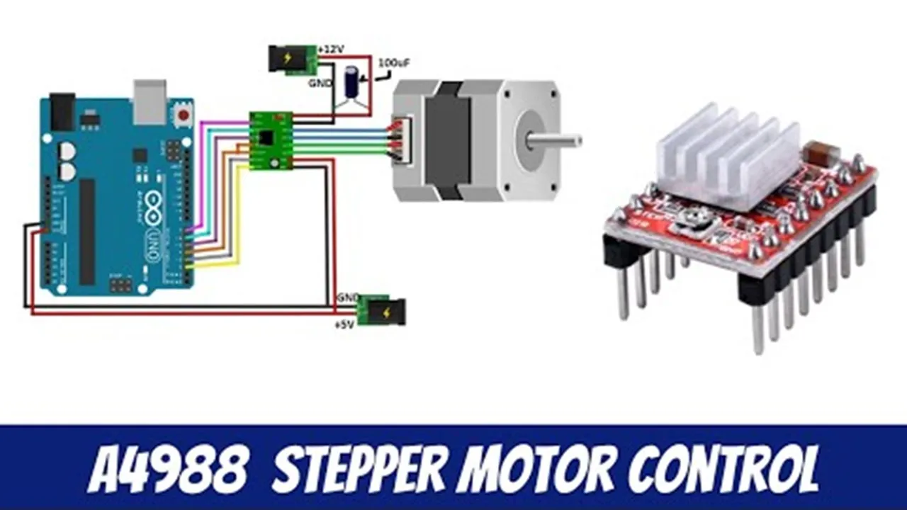
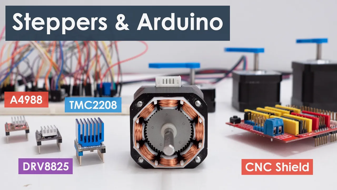
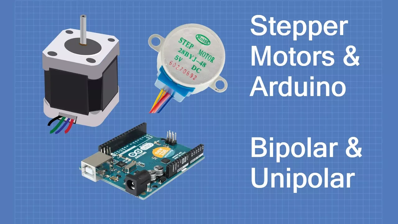
Fundamentals of stepper motor operation and motor driver boards (such as A4988 or TMC series).
Introduction to FDM 3D printing, including slicing software, filament selection, and tolerance design.
Basic mechanical principles of linear motion, including the use of timing belts, pulleys, and linear guide rails.
Advanced motion control programming, focusing on acceleration profiles (S-curves) to eliminate mechanical jerk.
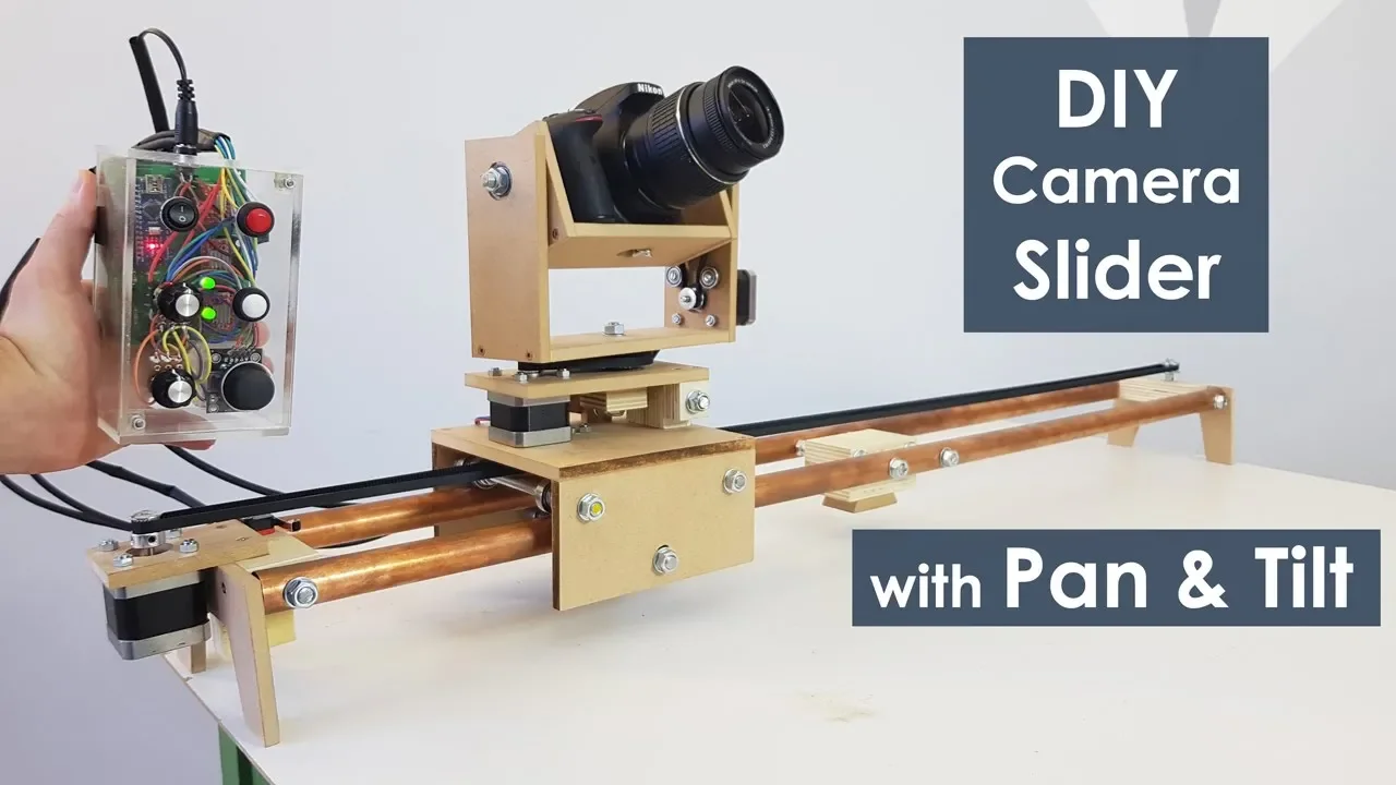
Expanding to multi-axis motion control systems, such as adding automated pan and tilt mechanisms to the slider.
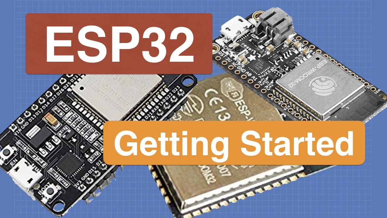
Wireless integration and remote control using ESP32, Bluetooth, or custom mobile applications.
Advanced cinematography techniques utilizing automated sliders, such as focus stacking, precise time-lapses, and parallax shots.
49.9K views2.2Klikes12:21Original Release: 2025-10-02
Close-up shots. Sound easy, right? Just hold your camera, bring it up near something. The gold standard for showcases. Let's try it. Hopefully, we won't get any shake.
[Music] Close-up shots like this are used in all genres from movies, shows, and product commercials, especially product commercials. These shots like this seem almost inhuman because they are thousand robotic arms swing the camera in smooth paths and arcs, but that is out of the scope of this video. Typically, amateur videographers have a choice of two options, a tripod for stability or handheld for freedom of movement. The tripod has very limited range of motion with high-end fluid heads being able to smoothly record tilts and pans. And that's pretty much it. If you decide to not use a tripod and opt for handheld shooting, you can say goodbye to stability entirely. Macro and telephoto recordings are certainly out of a question. There's just way too much shake and optical image stabilization does not help pretty much at all. In the middle, you can find gimbals, but most of these do not stabilize up and down motion, and they're nowhere near stable enough to record macro shots. My goal is to shift away from a tripod side slightly and introduce another axis of movement, linear translation, which would put it about here on the scale. My goal for this system is to have a super smooth and reliable physical zoom. Also, you can move the camera left and right, which is a huge bonus, too. Other camera sliders use belts, pulleys, and roller wheels, which makes the sliders cheap, but also very shaky and imprecise. I'm trying to make this as cheap as possible without sacrificing quality, and also just for a bit of fun. Seems like an interesting project. As a huge fan of 3D printers and CNC machines, I will be using stepper motors, a lead screw, and most importantly to provide stability, linear guide rails with several blocks.
None of this roller wheel rubbish. First of all, I'd like to thank JLCMC for sponsoring the video. JLCMC provides cheap and highly customizable mechatronic parts for you to use in your projects. I ordered these parts right here and they arrived in under a week.
The aluminium extrusion, bolts, T-nuts were all extremely cheap, beating most Asian suppliers in price. Also, JLCMC is more reliable and has a reputation, so most of the time you will get quality parts. These linear rails have been cut to a custom size and shipped with three blocks each. These cuts are almost perfectly flat and are exactly dimensionally accurate. I also have long M3x60 screws which are really difficult to find elsewhere. So I suggest using JLCMC. To place an order, go to jlcmc.com, find whatever parts you need, click on the product, select dimensions and specifications, and add to your basket. It's as easy as that. A list of parts is provided on compatibles page, and a link for JLCMC is in the description, too. Unfortunately, JLCMC's catalog does not have all the hardware required for this project, but ordering what you can saves you a lot of money. I will most likely be using the service from now on. I have ordered this PCB here from JLC2. Anyways, back to the video.
[Music] You won't believe what I tell you.
White coats and clever minds will choose.
You get a lot from this time and arrogance.
It's not appropriate.
Don't think that this is it.
[Music] [Applause] [Music] I have printed all these parts from PLA with four walls and 50% infill. PLA is fine, but if you expect a lot of wear and tear, use a stronger material like ASA, ABS, or something like nylon. Make sure these linear guide rails are aligned. I had to loosen all these screws later and adjust the rails as one of them was not quite parallel to the other. You can use similar spaces to the ones used on Voron 3D printers. You do not need to screw in all of the screws.
I have only used one screw per three holes. This large part in the middle had a problem printing in the corner here.
Uh the motors also couldn't fit as they needed to be rotated and inserting and that meant I had to redesign and reprint this part. While I was at it, I also reprinted the lid as the holes for alignment were slightly too small and the fit was really tight. I ordered these T12 lead screws from AliExpress, but they're 12.05 05 mm in diameter, which made them not fit through the bearings.
I dreme bearings, increasing the 12 mm hole to a little bit more than 12.05, and I was probably using the wrong bits, but it doesn't matter. It did the job.
Anyways, the rods fit perfectly. Since my vice is 3D printed, I used scrap plywood as an interface to prevent the TPU from melting. This project was designed to work with my bayonet mount tripod. I think that's what it's called.
It's sort of like Arca-Swiss, but a lot bigger. There's also a heat insert for a quarterin screw here at the base. This uses 8 mm heat head insert which you can get from a Bamboo Lab maker website thing. This slider is split up into two opposite sides, one for the camera and the other for the counterwe. You need this counterweight so that heavy cameras and rigs do not flip the slider. There are also feet so the slider can be used without a tripod entirely. These feet have their own heat set inserts if you want to design something to go there as well. Maybe if you want to use two tripods on both sides. And the feet also have notches for resting a slider at an angle, maybe against a desk on the floor or just some rope. I don't know. Use these for whatever you'd like. These knobs here on both ends allow for manual rotation of the lead screw to adjust the counterwe and set the position of the stylers themselves. I would personally cut these down a little bit more just to reduce this gap here. This screw point can be attached to a camera directly or to another tripod head which can be attached here as long as it uses a/4in mounting hole as well. You can really use any tripod head. An AliExpress one will be just fine. Otherwise, a fluid head that can pan is ideal. The mounting area is also flat, so pretty much anything can be attached here, even a phone holder. Oh, and ignore this little bit of damage here. I tried to glue on rubber bands to make the hole a bit more secure and um they got ripped off when I was moving the camera. On the opposite side here, an anodized metal box is screwed onto a mount. This side only uses one slider per rail as it's not really important to keep a counterweight rigid. Ideally, use a keyboard of steel or aluminium milling stock, but this box can be filled with pretty much anything heavy as just maybe some metal scraps, nuts, and filling the rest of concrete.
I was originally going to drill holes through here, but the position of a holes in the box would make a screw head or the nuts not quite fit in the inside.
So, I just glued it myself. I suggest you use a slightly bigger box, drill holes, and screw it in place. So, what did I use to counterweight it?
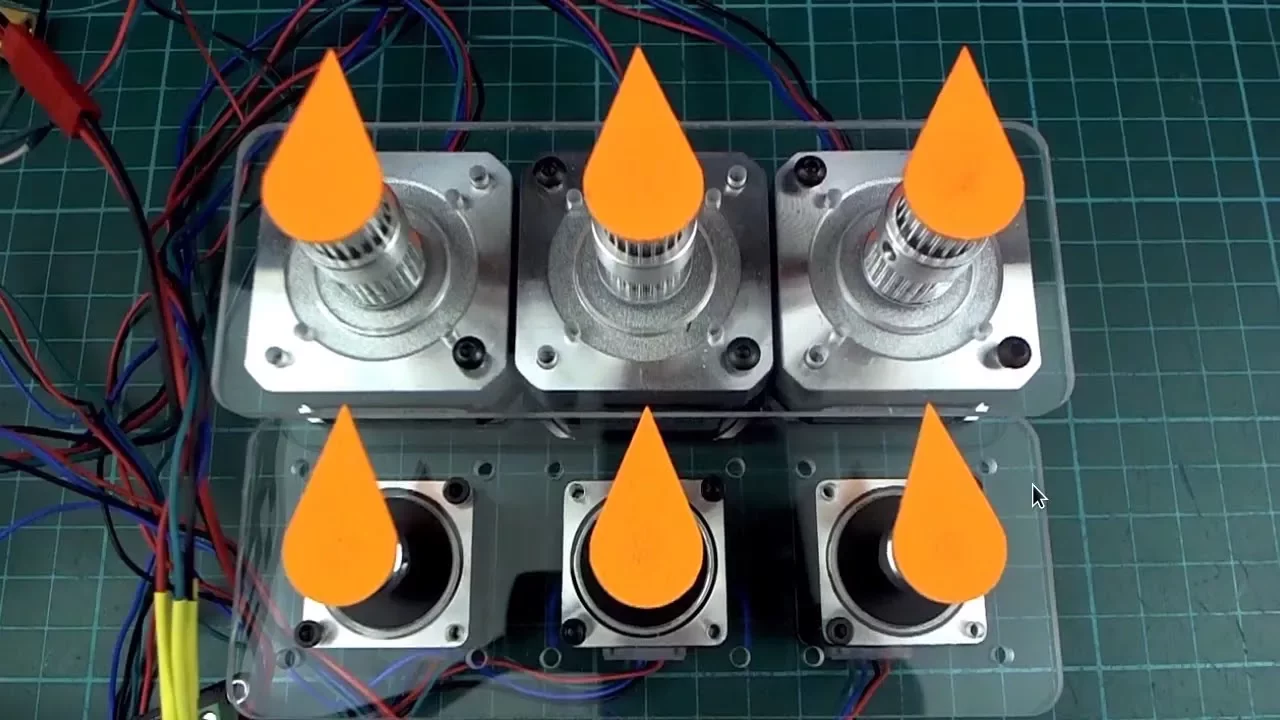
[Music] Well, I had to cut down some steel, which was not very fun. Anyways, try to match the weight of your camera. It doesn't need to be too perfect, but aim to have it as balanced as possible. Make sure your tripod can support the doubling of a way, too. My small rig tripod barely manages to hold everything up. The middle here is where the magic happens. Two Nema 17 motors are placed back to back and are connected to the lead screws with a shaft coupling. I use some lithium grease to stop it rattling.
The outputs are connected to this PCB above and this board only has three holes, making soldering really easy.
There's a slot for an Arduino Nano, a buck converter, and two stepper motor drivers, allowing you to individually control the motors and change their speeds. Most motor cables are about a meter long, so I suggest cutting it down. You can solder the cutwise directly to the three holes here. And the headers that I've put on aren't really needed and are a bit of a burden.
Also, they look kind of bad. Check if the wiring is correct and if the motors spin in red direction. If they don't, it's not a big deal as rotation direction can always be fixed in software. And it's not a huge deal.
There's a dedicated direction pin on these stepper motor drivers, so you can pull it up or down and they will change direction. Really, really easy to implement. The most important thing when soldering this motor is getting your coil windings correct. I suggest looking at this diagram here. Also, make sure to break this pin off from a potentiometer.
The metal on this is made from the cheapest Chineseium metal they could find on the factory floor, so some pliers or old damaged side cutters should work. work just fine. Make sure not to use new side cutters as they'll probably get damaged. So, this PCB has been designed to be as simple as possible to make. There are no SMD components and you don't need a pick and place machine or even a hot plate for manual SMD soldering. Everything could be assembled with just a soldering iron.
Make sure to set the buck converter voltage before soldering in the Arduino and stepper motor drivers. If the voltage is set too high and you turn it on, a lot of this stuff will probably break. Also, make sure to cut the pins off on everything on the bottom side, too, as they're a little bit too long.
The capacitors I've used are a bit too small. I suggest using 50 to 100 microfarad capacitors which are short and wide. And also make sure that they're rated for about double the operating voltage about maybe 50 volts.
There's only one input, a potentiometer.
In the middle, the slider doesn't move.
When rotated right, the camera moves forward, and when rotated to the left, the camera moves back to the middle.
There will most likely be a sweet spot where there is very little noise and almost no vibration. Try to aim for that. There also micro stepping pins which allow for coarser speed control. I will discuss these later. The top half of this is rotationally symmetric. So the switch on the bottom can be placed on either side of a slider. I prefer to keep it on this side. Also, this control method with one potentiometer is very bare bones, but the Aduna Nano can be programmed however you'd like, making movements really easy. Also, you can make your own circuit board. You can connect the stepper motors to another thing entirely. It's all up to you.
Also, speaking of modification, the frame is made of 2020 aluminum extrusion. So, adding anything requires some T- slot nuts, and that's pretty much about it. These often come in M3 to M5 sizes. An upgrade that I'd make is to add a power delivery battery bank and a 20 volt decoy board. This decoy board tricks the power supply into delivering 20 volts through USBC and allows the slider to be used pretty much anywhere and you don't need to plug it into a DC power supply. Oh, by the way, when assembling this, the switch should be soldered on last when everything else is already installed. Speaking of power, there should be a slot at the back for 24vt input. This can be supplied however you'd like. Uh, I'm using my benchtop power supply here, but I plan to get a dedicated power supply for this thing as well, too. and I'll most likely bolt it to a bottom somewhere. After assembling everything, I gave the linear guide rails a light coating of lubricant. Now, let's go and try this thing out. And every day the paper boy brings more.
[Music] [Music] Heat. Heat. Heat.
I see you on the dark side.
[Music] >> Now, I'd like to thank all of you for being supporters of the channel. My last video has gotten over 50K views, which is pretty insane, and my subscribers jumped to about 5 to 6K at the time of filming. If you've enjoyed this video and are interested in 3D printing electronics, consider hitting that sub button. And I've got a project in the works which you might enjoy. Anyways, as mentioned before, motor speed can be controlled with this potentiometer here which is connected to an analog pin of Arduino. Your sensitivity of this dial can be adjusted in code. But you also have an option of changing the speed on the PCB itself. By placing jumper connectors on these pins here, you can control micro stepping as shown in this image here. By adding on these jumper connectors, you exchange speed for smoothness. When there are no jumpers, this thing moves fast. But when all three are installed, the movement is very slow but also very smooth. This is perfect for macro shots and possibly time-lapses. Just make sure to keep an eye on the slider so it doesn't run out of room as there are no limit switches on either sides, but that could be an upgrade for a version two. Putting limit switches at the end could also let you do auto homing, which I think is quite nice. As another thing, I suggest you add heat sinks to these stepper motor drivers here. After a while of use, they do get quite hot. And careful not to set the speed too high. This can cause the motor to skip steps or act jittery. To get more speed, again, reduce micro stepping. Now, if you want to go the extra mile and make your video even more smooth, software stabilization helps you make your video just that little bit smoother. Step files are also included in the project description, so you can modify it however you'd like to. You can also choose to have no electronics at all, moving the slider by hand. It won't be as smooth or repeatable, but it saves a lot of cost. The middle part here can be removed entirely, as well as this counterwe. This frees up space for the entire 1 m rail for the slider. Also, keep in mind that there's no limit for how long the slide can be. I was originally planning on this thing to be 2 m long, but I decided against it as that will be too big to practically use in my area. Anyways, that pretty much concludes the video. Check out the project on the printables and the JLCMC.
Anyways, also subscribe and I hope you enjoy the video and I will see you in the next project.
[Music]
Up Next

2:10
Scotch Yoke Mechanism: 3D Motion Analysis
@SkylineTutorials
730.5K views•2016-01-06

30:21
Damped Free Vibration of Structures: Viscous Damping Theory
@IITKanpurNPTEL
23.4K views•2019-08-26

54:16
Polymer Environmental Degradation: Mechanisms & Stabilization
@iit
1.8K views•2012-07-10
33:39
How a Student's Question Saved a NYC Skyscraper from Collapse
@veritasium
22.8M views•2025-04-26
Related Study Plans & Knowledge Roadmaps
Structured learning paths in Engineering
engineering
Structural Dynamics (DIY TMDs & Shake Tables)
01Foundations of Structural Dynamics & Resonance
02Designing and Building a Motorized Shake Table
03Constructing the Scale Building & Tuned Mass Damper
+ 2 more learning modules
35h5 modules
Explore Roadmap
engineering
Building Acoustic Levitators: Physics & Arduino
01The Physics of Sound and Standing Waves
02Piezoelectric Transducers and H-Bridge Drivers
03Arduino Programming: Generating 40 kHz Signals
+ 2 more learning modules
14h5 modules
Explore Roadmap
engineering
Building Peltier Cloud Chambers: Particle Tracks
01Cosmic Rays & Cloud Chamber Physics
02Thermoelectric Cooling (TEC) Fundamentals
03Custom Liquid-Cooling Loop Design
+ 2 more learning modules
18h5 modules
Explore Roadmap
engineering
Yagi-Uda Antennas: Modeling, Build & VNA Test
01Introduction to RF and Antenna Fundamentals
02Yagi-Uda Antenna Design Principles
03Antenna Modeling and Simulation in 4NEC2
+ 2 more learning modules
18h5 modules
Explore Roadmap