









![ZIEGLER NICHOLS ✅ SEGUNDO Método [Control PID] Parte 2](https://i.ytimg.com/vi_webp/AAaWNNuqpuY/maxresdefault.webp)








This tutorial demonstrates how to manually tune a PID controller to stabilize an inverted pendulum using the STEVAL-EDUKIT01 kit from STMicroelectronics. The process involves setting Ki and Kd to zero first, then gradually increasing Kp until the system approaches the setpoint with minimal oscillation, followed by tuning Ki to eliminate steady-state error, and optionally adjusting Kd to reduce overshoot. The Arduino reads encoder values and drives the stepper motor, while Python code running on a computer implements the PID controller algorithm and generates graphs for visualization. Properly tuned PID controllers can achieve critically damped behavior where the system reaches the desired upright position (180°) quickly without excessive oscillation or overshoot.
Manual PID Controller Tuning for an Inverted Pendulum | DigiKey
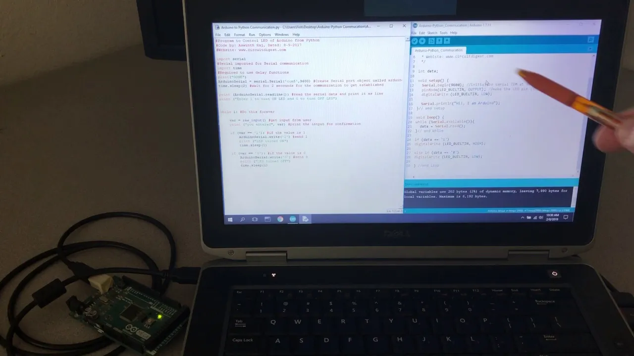
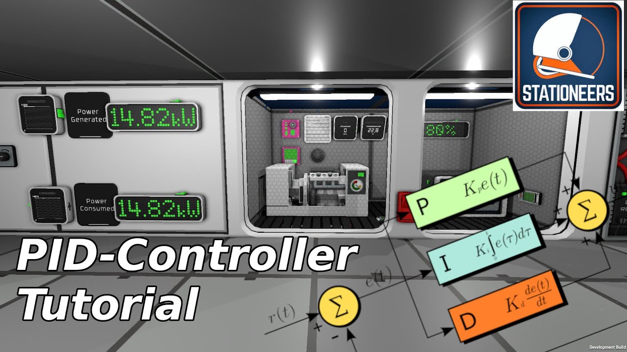
Added:ah the inverted pendulum getting one of these to work is a little bit of a WR of Passage if you're studying engineering or more specifically control theory the concept is fairly straightforward we have a weight or in this case a simple metal rod that can move freely about an axis and as you can see here once the program stopped it just freely fell over because it's in an unstable position when it's upright but our job is to create a controller that takes in encoder values that is the angle in which this Rod is pointing and then controls the stepper motor so that it stays upright we won't try to do the swing up where it gets it into that position we'll just assume that it starts in the upright position and our controller will need to keep it there the Arduino in this case is just going to act as an interface for us it's going to readin values from the encoder and then send Commands to control the stepper motor all of our coding will be done in Python for the controller so that we can make pretty graphs and it will help us tune the controller more easily so with that in mind let's get [Music] started a PID controller is an instrument device or code that uses feedback from a sensor to regulate a process or system PID stands for proportional integral derivative which describes how the feedback information is used to create a control signal for the process if you would like like to dive more into the theory behind PID controllers I highly recommend checking out my previous video in our system we want our pendulum to sit upright which we're going to call 180° and we'll use a PID controller to make that happen the input to the controller is the error term which is the difference between our desired set point and the actual sensor value or feedback the output of the controller is used as the input signal to our process or plant in this case it will be how many degrees we want to move our stepper motor by the process gives us some kind of value to measure in this case it is an encoder angle which is used in the feedback loop to compute the error term in some cases we can mathematically model the process many inverted pendulums can be modeled if you know the weight size and so on however in many real world situations it is very difficult or impossible to model the system we want to control so we turn to manual tuning methods for our controller while there are several tuning methods we'll stick with the most basic first we'll set the integral and derivative constants to zero and guess at some value for the proportional constant with a KP too low we won't get anywhere near our set point we then adjust it so that our output gets close to the set point with maybe some oscillations from there we tune Ki so that we oscillate around the set point without causing the system to become unstable in many cases a pi controller is enough however we can often tune the KD term to remove some of that overshoot with KP Ki and KD set we have a fully tuned system here the output quickly approaches the set point without over shooting we'll run some code on the Arduino remember that the Arduino is simply acting as an interface for us it's not doing any of the actual control code for us it's going to read in values from the encoder and send out information necessary to control the stepper motor if we scroll down to the top here of our code we are using the L 6474 that's an st microelectronics code that's a library for our Arduino that allows us to control the stepper motor we're also using a library called rotary encoder that just gives us angle information from that coder if we click over to the control comms interface file scroll down a little bit you can see we have an object here control comms and there should be two basic functions well we have our Constructor and our anit we also have send observation which sends information back to the PC in our case it's just the angle of the encoder as well as the angle of the stepper motor in addition we have receive action this just waits for an action to come from the PC that says what to do we're going to put in this our angle that we want to move the stepper motor by say for example move by 3° or -3° in the opposite direction so if we go to our main interface program here scroll down to where we see setup we configure everything and then in Loop we simply wait for those actions to show up for us from the PC side we move the stepper as requested Say by a certain number of degrees we get the incoder and stepper angles we put those into an array and then we send that observation back to the PC and that is our entire Loop and how we're going to control our inverted pendulum on the python or the PC side of things we have our control commoms interface this is the PC version of that control commoms HPP file that we looked at in this case we have a similar object called control comms we can get a list of Serial ports which helps us figure out what we need to connect to we can connect to our serial Port which opens up a connection to the Arduino board we can close that connection and then the important thing here is this step function for us we give it an action and some sort of command say move by or move to or reset which says to make whatever position the steper motor is in home that information gets sent to the Arduino the Arduino performs that action and then returns an observation to us which is a status in this case it's just some userdefined code that we're not going to use very much a timestamp which is useful to see how long it takes to compute some things whether it's terminated once again we're not really using that here and an observation in this case it's going to be the angle of the encoder and the angle of the stepper motor you can see that code here where we send out the command along with the action we wait for a response we decode that in Json format and then we return with those results here's the status timestamp terminated and our observation array and this is just for testing down here now let's look at the actual PID controller code this is the part we care about I'm going to execute these cells but I won't get into the code very much because I want to spend more time on tuning the controller where we fiddle with the constants in order to make make the inverted pendulum work so from the top here we're just going to import some libraries we're going to set our constants in this case my Arduino is connected to Comm 6 I'm using a ba rate of 500k and I've assigned a timeout of 1 second in case something doesn't work where I can't communicate with that Arduino board I also set my debug level here so that I can get some information from my control comms python library that I've created we've got some communication constants that we will be using in this case we're going to be using stepper mode8 which is eight divisions per step and we have some commands we can send out such as setting home move to move by and setting our stepper mode I'm going to close that connection to the uino that's just a safety thing make sure it is actually closed and then I'm going to reopen that connection so now I can talk to the Arduino board first I'm going to test the control to make sure that it actually moves the idea here is that the stepper motor should be able to move fast enough such that it can recover from a say plus or minus 10° offset from being vertical if we go back to our Arduino code here you can see the configuration that I set up for the stepper motor I'm using the St microelectronics L6 474 library and I've set the acceleration to to very high it should get up to Max Speed very quickly I've set the maximum speed to 5,000 which is about half of their maximum that seems to be a good compromise between giving me a very high speed that it can correct for a 10° offset from vertical while not being very jittery in its motion so you want to find that balance so I played with these parameters to find a good balance note that this can take some time and I was just doing this by field before moving on and tuning the PID controller once we verified that this control works it's time to tune the controller here I've set up my K constants here's PID sometimes you will need a bias which we just add to our output of the controller in many cases a p controller is fine and you just need a simple bias and this will do it sometimes you'll find that even with P ID there's a little bit of an offset so you add up bias term we may not need that for this particular project but just keep that in mind there are other constants that you should keep in mind our set point is 180 that's 180° that's the rod facing up we're going to run this for let's say 5,000 steps that's a good indication of whether this is working or not we have guard degrees here so we want the rod at 180° at 160° or 200° we assume that the rod has fell over far enough and it's a lost cause and the program or in this case this particular cell will just stop we're going to do eight divisions per step that seems to be once again a good balance between having the stepper motor move quickly while still giving us enough control without having a lot of Jitter we're going to store the metrics so that we can plot them later the first thing we're going to do is set the stepper mode to those eight divisions per step and then we're going to set home wherever the stepper motor is facing we're going to call that 0° we're going to send that out and get our first time step then we'll try to keep the pendulum in the upright position this is the actual P controller we'll first take a step and get that observation so we take a step by telling the stepper motor to move by some amount this move degree starts off as zero and that's what gets updated as the output of our controller when we get our response response we're going to unpack that response to get status time step terminated and our observation which is an array we unpack that array here the first element of that array is the encoder degrees and that's what we really care about the second is our stepper degrees note that you could create a dual PID controller here whether that's an inner and outer or side by-side controllers where you can then try to keep your stepper motor in the same spot rather than rotating but instead of doing two controllers we're going to keep it very simple and just do our One controller consider that a challenge for you if you want to take this further try to keep the stepper motor in more or less one position rather than having it spin around that axis we're going to calculate the time between this step and the previous to get our interval which we need in some of our calculations and then we're going to record the previous time step so that we can use it on the next iteration of this Loop then we're going to calculate our PID terms well first find the error which is the difference between our set point and the current encoded degrees which we got from the observation this error term is going to be used in our proportional calculations where we just multiply it by KP next up we get the integral term which takes the integral term from last time this starts at zero and we accumulate that value with the error times our interval from there we get our derivative term which is the previous error subtracted from the current error and divided by our time interval we then sum all of these terms up after we've multiplied them individually by their K constant so integral gets multiplied by Ki derivative gets multiplied by KD and as we saw earlier error gets multiplied by KP or the proportional term we also add this bias term I would leave this at zero unless you absolutely need it try to solve everything else and get that working if you still still need that bias term go ahead and add it finally we save the error term for the next iteration so we have that previous ready to go for our derivative calculation next we're going to store these metrics in Array so that we can plot them and we're going to check if the encoder goes past one of our set guard angles so if it's less than 160 or greater than what was it 200 I think yeah 200 it's just going to stop the whole episode and break out of this Loop finally we're going to use matplot lib to plot a whole bunch of stuff for us and we will take a look at that when we tune our controller before we tune I'd like to show you where you can go to get this code head to github.com shanil pendulum dpid all of the code that I'm showing you is in here if you would like to try out your own version of this PID controller to control the inverted pendulum kit from St micro Electronics now let's get to tuning our actual controller as I mentioned earlier the first thing we want to do is make sure that our stepper motor can recover from about plus or minus 10° so when I run this cell here I'm going to offset this uh by about five or 6 deges see oops wrong way let's try that again so it's moving at 90 so I'm going to hold it about here yes it goes goes the other way so that means the stepper motor is capable of correcting from that amount now let's get to tuning I'm going to start off with one for the proportional and zero for the others I'm just going to guess at one and let's see where that gets us so I'm just going to hold this here and say go okay so it looks like it's jittering a lot and then it's struggling to keep up at the end there let's take a look at our output sure enough there's a lot of oscillations which means that our value for KP is a little too high let's try adjusting it so we're going to go up here let's move it to 0.1 and let's try again ah okay so there weren't as many oscillations there but you could see it struggling to keep up and if we look at our plot sure enough it never quite reaches our set point and it just kind of struggles to keep up that means KP is too low let's try 05 about halfway in between we'll run this again okay not bad there's some oscillations and in fact I want to run this again be prepared to run some of these cells multiple times oh okay still some oscillations it's oscillating around that 180 point so it means it's a little too high still let's bring it down just a notch we're going to take it to3 let's see what happens oh that's really good that keeps it for a while not much on the oscillations and it's just struggling to keep up this is what we want we want the integral term to make up this difference this is that steady state offset between where the set point is and where it's trying to get to or as best as it can get so we're going to keep it at three and see if we can get ki our integral term to make up that difference I'm going to guess at 0 one it usually starts much lower than KP so let's try that and see what happens oh what just happened there let's try that again oh it's oscillating badly and then it whips around let's go take a look at our plot and here we go sure enough it's unstable you can see it bouncing back and forth and getting larger and larger before it loses control that's unstable that means that Ki is definitely too large let's move X exponentially here so rather than say having this let's go to 01 and see what happens oh wow that's really good actually that's almost where we want it still look like it's oscillating some so let's stop that go take a look at our code yeah there's still some oscillations here you can see it hitting up too high in the beginning and then it's oscillating a bit let's see if we can bring that down just a little bit and in fact let's go probably too low and see what happens start it here that's not bad at all oh it's losing it here okay so something between 0.1 excuse me 0.1 and 0.1 looks to be ideal so let's say 0.005 for the sake of argument and try that oh that's yes this is what we're looking for it's barely moving and it's keeping it upright and I can touch it and it corrects and let's see if it recovers from that oh I got to touch the other way before that gets too wound up around that axle and then it goes the other way so there's some larger level oscillations going on in here but this should be okay let's scroll up yeah 05 seems to be really good now we can take some time and really tune these but I think with a KP of3 and a Ki of 05 going to be good enough for now and our demonstration as you can see this Pi controller pretty much does the job for us we probably don't even need a direct derivative term in here but let's just play with it and see what happens we started with zero which is a good place to start I'm going to guess 0.1 just to see what happens once again this is usually lower than the KP term so let's try this this is actually not too bad okay let's take this down and take a look at our graph here it's looking pretty good and just for argument what if we take it to 0. five what happens this thing's still a beast it's still going uh looks like it's a little unstable we're getting some of those oscillations which is probably fine for this okay that's fine and just so you can see what happens when we really crank this up let's take it to five and really try to make this too high yeah there we go we're getting too many of the oscillations and it's pretty unstable it can't control it so that means we are suppressing Ki and KP a little too much and sure enough uh you can see it with this encoder angle it's struggling here okay so we know we got to be less than five and what happens if we take it really low like 001 once again it's pretty good we can't really go too low with this I'm going to stop it there we can't really go too low all we're trying to do is suppress this peak here or any of the Peaks where it overshoots our set point and in this particular system an inverted pendulum we don't mind a little bit of overshoot sometimes you can't have this overshoot so you need KD to suppress that but for our system it looks like anything between like zero and one is probably fine for your KD so I'm going to maybe make it a little higher as we saw with one is not too bad five was too high let's see what happens with one yeah that's pretty good there's still a little bit of Jitter happening here but once again I don't think that's because of the KD term yeah this is really good it's moving back and forth It's accomplishing its purpose of keeping the pendulum upright and from that I think we can safely assume we have a fully tuned P controller for our inverted pendulum if we go and look at our plots you can see the encoder angle stayed pretty static the whole time there's a little bit of an overshoot by about 2 and 1 12 deg on that first one but it's really not bad and then you can see the stepper slowly oscillating back and forth that's something that can be corrected with a dual or nested PB controller but not something we're going to get into right now just so you see what happens we're going to leave bias at zero it actually works very well let's try 10 for the bias term and see what happens so I'm going to yeah exactly nothing it's trying to overcorrect for something that's not even a problem we might be able to bring this down let's say five okay it's still working it's not particularly great as you saw there's no real need for this bias term in this system so I'm just going to leave this at zero let's put this bias term back at zero and we're going to call this pretty tuned for our needs as you can see it works pretty much most of the time it will move back and forth a little bit and that's something that could be corrected with additional control schemes but for now I'm going to call this good enough I think we can say we have a fully tuned system there's obviously some other tweaks but let's go with that for now I hope this helps you get started creating your own PID controllers and then tuning them for things like inverted pendulums or self-balancing robots obviously there are more complex control schemes out there such as linear quadratic regulators and model predictive control but PID controllers are a great introduction into control theory if this is something you would like to Tinker with good luck and happy [Music] [Applause] [Music] hacking
Up Next

GATE BT Bioprocess Engineering Revision: Key Formulas Part 2
@InstantBiologybyDrNeelabh
1.4K views•2022-02-08

Ultrasonic Transducers: Resonant Frequency Measurement and Horn Design
@imajeenyus42
229.9K views•2017-02-22

Polymer Environmental Degradation: Mechanisms & Stabilization
@iit
1.8K views•2012-07-10

How a Student's Question Saved a NYC Skyscraper from Collapse
@veritasium
22.8M views•2025-04-26
Related Study Plans & Knowledge Roadmaps
Structured learning paths in Engineering