






![[LIVE] Image of Sagittarius A * [Milky Way Black Hole] | Event Horizon Telescope ⚡🔭🌎✨📡](https://i.ytimg.com/vi/4Ws0iPDSqI4/sddefault.jpg?v=627da2f5)








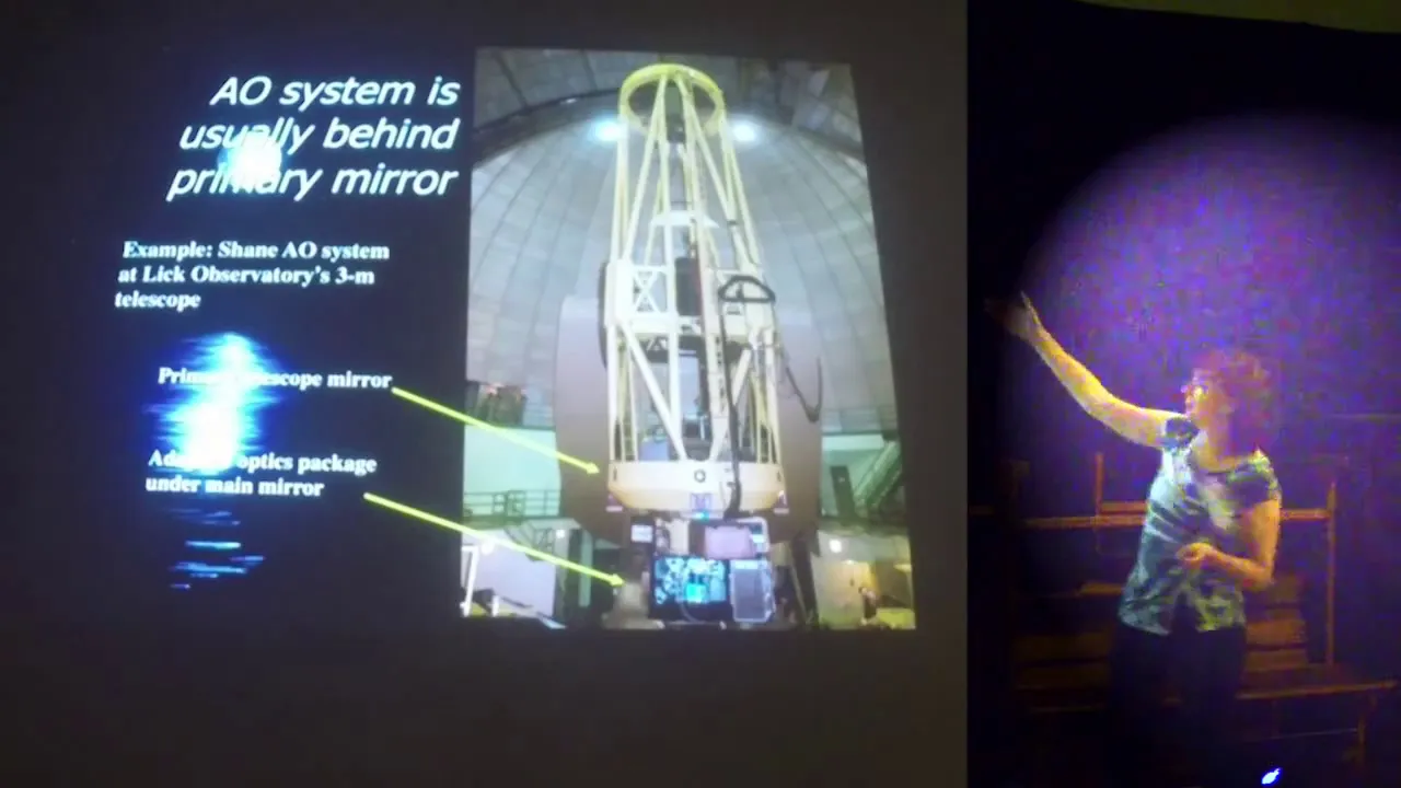






Wavefront sensing and control is essential for correcting optical aberrations in both ground-based and space-based telescopes; wavefronts are surfaces of constant phase in light waves, and atmospheric turbulence causes these wavefronts to become distorted, creating speckles and image blur that deformable mirrors can correct in real-time using wavefront sensors like Shack-Hartmann, pyramid, or Zernike sensors, which transform phase variations into measurable intensity patterns to enable high-resolution astronomical imaging.
Wavefront Sensing and Control Basics for Telescopes
Added:Understanding of wave optics, specifically the concepts of light waves, phases, and the definition of a wavefront.
Knowledge of atmospheric turbulence and optical 'seeing', including how temperature and density fluctuations in the atmosphere distort incoming light.
Familiarity with basic telescope optics and the diffraction limit, which defines the theoretical maximum resolution of an imaging system.
Basic principles of control theory, particularly closed-loop feedback systems involving sensors, processors, and actuators.
In-depth analysis of specific wavefront sensors, such as the Shack-Hartmann, Pyramid, and Curvature sensors.
Study of deformable mirror technologies (e.g., piezoelectric and MEMS) and the mathematical algorithms used for real-time wavefront reconstruction.
Exploration of Laser Guide Star (LGS) systems and how they bypass the limitations of Natural Guide Star (NGS) adaptive optics.
Investigation of advanced frameworks like Multi-Conjugate Adaptive Optics (MCAO) and Extreme Adaptive Optics (ExAO) for exoplanet imaging.
272 views3likes43:42Original Release: 2024-07-24
okay hi everybody um thank you so much for having me here uh even though it's remote I know that it can be a little bit challenging to stay engaged through a remote talk so I'll try to make this as entertaining as possible as we go um how's my sound good we're working on getting you a little bit louder okay I will I'll keep talking as you do that yes okay um so I'm an associate professor at UC Santa Cruz um I have very fond memories of attending the seen summer school as a graduate student and so um I hope you're all getting a lot out of this week uh there at keltech um okay so I'm gonna go ahead and get started um if someone comes up to the podium and gives a thumbs up or thumbs down I'll try to respond to that um but I'll just I think you're good to go I think you're good to go now okay wonderful um okay so this talk is about wfront sensing and control so first I just wanted to make sure that we're all on the same page of about what a wavefront is so if we think of uh light's electromagnetic field um and we consider a star who is emitting light uh uniformly in all directions then the surfaces of constant phase in the Starlight electric field are what we refer to as a wavefront so a good analogy to consider is if you dropped a pebble into a pond as you see in this figure and you see the waves Rippling outward you could draw circles along for example the crests of those waves those would be the surfaces of constant phase those would be your wavefronts okay so now if we're imagining um a star that's um has the circular or if we were in three dimensions um spherical wavefronts um that it's emitting uniformly in all directions then by the time that star Light reaches us on the earth those um spherical or circular wavefronts are so stretched out that we can pretty much think of those as being um plain waves as being flat so those Starlight wavefronts are traveling to our telescope um if we had an idealized Space Telescope then uh we would bring that light to a focus and we would have our idealized Airy dis and in some of the Optics lectures that you had yesterday um you were probably acquainted with the point spread function U the classic a dis whose full with half maximum is approximately Lambda over D so with no turbulence or no other Optical aberration um that is the characteristic size of your point spread function um with atmospheric turbulence that image size is going to be much larger typically on the order of something like half an arcc to even two or several arccs um in very poor seeing um even space telescopes um have to contend with the effects of optical abberations so the Hubble Space Telescope famously was accidentally launched with the wrong prescription um and that led to poor image quality until that was corrected with upgrades later um telescopes that are segmented like the James Webb Space Telescope and like the future um plans for the habitable worlds Observatory um are going to have segmented primary mirrors and those um primary segments need to be very precisely co- phased so the positions or the Pistons of those segments have to be aligned the tip and tilt of each of those segments also has to be uh just right and if they're not just that also leads to uh Optical aberration similarly as the staright passes through the Optics in a Space Telescope it's going to encounter different imperfections in those Optics that are going to lead to aberration those um it's the lights path through those objects is not going to be exactly uniform over time um for example due to pointing Jitter um due to Thermal variations in that Observatory so some way of dynamically correcting for optical aberration is very much needed in space-based telescopes especially in a high contrast Imaging context as well as groundbased telescopes okay but of course groundbased telescopes have very particular challenges so as The Starlights or astrophysical objects wavefronts propagate through the atmosphere it encounters different pockets of air and those pockets of air are going to have some slight temperature variations between them and those temperature variations give rise to index of refraction fluctuations and so some parts of the wfront are going to be delayed relative to other parts of the wfront so this is how the atmosphere gives rise to uh wfront aberration so instead of that perfect Airy disc what we might see on the ground if we were taking millisecond exposures might look something like this animation so what we're seeing with our telescope are images that are representative of a combination of many Airy discs at different locations and these are called Speckles um so each of these area discs is still defined by the defraction limit of the telescope um but now you have many realizations and of course the centroid of this entire um psf is moving around um so that's where we get image motion as well as the image blur so this is what we have to deal with in a groundbased telescope now where does turbulence arise so turbulence can arise in a large variety of locations so starting with inside the Dome of your Observatory it may be that the telescope's mirror um is hotter and takes longer to cool down than the air in the dome surrounding the mirror um as the night goes on and so the mirror is giving off heat and that can lead to turbulence uh just next to the surface of the mirror um similarly you can have what's known as Dome seeeing as air is blowing through the Dome you can set up turbulence even inside the Dome um that's why you'll see observatories are designed with specialized um openings and Lubes to try to um influence how the wind flows through the telescope to minimize um this kind of Dome seeeing um and the Wake um behind the um Observatory um we also have turbulence at what we call the boundary layer um the boundary layer is the lowest part of the troposphere the part of the atmosphere that we live in that's directly influenced by the Earth's surface um so it's responding to forcing um from surface on say hourong time scales now above the boundary layer so above a kilometer or so we have what's known as the free atmosphere where you might have turbulent wind layers uh with some fairly constant velocity and then as we continue upward through the atmosphere at about 10 kilomet uh we have the tropopause um this is the transition between the troposphere and the stratosphere and so often times we'll see turbulence peaking near the tropopause due to a strong wind shear so wind of different velocities that's kind of colliding at the tropo pause okay so an Adaptive Optics system or any kind of wfront sensing and control system is designed to correct for optical aberration in real time so if we imagine our aberrated Starlight here at the top that's been collected by our telescope and directed to our Adaptive Optics instrument um coming in on the upper left hand side the first thing it typically Encounters in your AO system is going to be the deformable mirror okay so a deformable mirror um in an idealized scenario Works something like this so on the left hand side you see an incoming wave uh with some kind of Step function uh wavefront aberration you see there so some part of the wfront here is sort of aead of the rest of the wfront now that wave is going to encounter the deformable mirror and The deformable Mirror Has a shape that's designed for the part of the wfront that's ahead of the rest to now be appropriately behind the rest of that wavefront so that after the light has bounced off of the DM that wavefront has become flat again now uh there are different designs of deformable mirrors um there are what's known as continuous face sheets um so you can have one single mirror surface and then behind uh that mirror you might have some kind of actuator that's pushing and pulling that continuous mirror surface uh we also have segmented deformable mirrors um so you might have say hexagonal segments kind of like a miniature version of a segmented Space Telescope mirror um and those might be pistoned and and tipped and tilted um but all of these um in an Adaptive Optics context are designed to do the same thing which is correcting for the wfront aberration so I'd like to talk a little bit more about the key requirements for a deformable mirror okay so one of the most important requirements has to do with the number of deforming elements or the number of degrees of freedom that you have on your DM so um a good way to think about this has to do with the spatial scale of atmospheric turbulence so the spatial scale of turbulence is described by what's known as the freed parameter or are not um some of you may have yourself or have seen uh we have these mugs um from spie a couple of years ago that says we are not seeing limited so that was in honor of the late um freed who passed away a couple years ago so we could spend an hour two hours deriving the free parameter are not uh but instead of doing that today I'm just going to quote um the definition of rot to you now so rot has to do with the wave number K the Zenith angle Z and then the integral of What's called the CN squar profile which is really just a measure of the strength of the tribulant at different heights in the atmosphere um and then this um definition of the free parameter is based on kagra statistics and that's where the minus 35ths power LW comes from so if we imagine mention as in this figure that we have our primary mirror we have the wavefront that's been affected by atmospheric turbulence arriving at our primary mirror we can think of the characteristic length um of these wfront variations due to turbulence as being about R not so we need to have um about our not uh degrees of freedom on our deformable mirror across the DM so in other words the total number of subapertures on the DM should be about D over r squared um and R is of course a wavelength sensitive quantity so you'd want to make sure to evaluate that at the wavelength that you plan to do you're observing so that tells you something about how many degrees of freedom that you're going to need on your deformable mirror another key requirement has to do with the dynamic range so how much do you have to be able to deform the DM um so again from turbulence Theory we can derive that the variance across the wfront scale as the diameter of your telescope divided by that all important R not parameter to the 5/3 power so for kek this is going to be something like a few microns but for elts it's going to be tens of microns because it depends on the diameter of your telescope as well as R not so this is partly why uh designing DMS for Next Generation large telescopes can be a technical challenge um this is also the reason why um systems such as the Gemini Planet imager will use two different deformable mirrors to do their correction they act like a woofer Tweeter speaker system where one has a larger number of actuators um but with a smaller um amount of stroke or smaller amount of change that they can create and then they will also have a low order deformable mirror that will have fewer actuators um but which have a larger dynamic range or larger stroke um now the second one I wanted to highlight is the temporal response of the DM so the DM should be able to respond much faster than the characteristic um time scale of atmospheric turbulence now the characteristic time scale or coherence length of atmospheric turbulence is given by that freed parameter um divided by the wind velocity where we can weight the velocity based on the CN squ profile that tells you about the strength of turbulence as a function of height in the atmosphere so A good rule of thumb is that the DM um should be able to respond you know at about the 01 times the coherence length um time scale which is you know maybe a millisecond or so in the near U and then finally the influence functions on a DM um need to be a good match between how thick the deforming surface is and how widely spaced your actuators are so for example if your mirror is too thin um then when you poke one actuator you might get a an overly isolated bump however if it's too thick then you might have some large section of the mirror that's displaced when you poke only one actuator and then finally there are other considerations such as the surface quality you don't want it to be too rough because you're not going to be able to correct that given that this is the optical element that you're using to do the correction um hysteresis and power dissipation U Etc so here are a few images of different DMS um you have continuous phase sheets um you have devices that are more on the scale of a centimeter um the ztics ones that I showed are on the scale of tens of centimeters and then you also have adaptive secondary mirrors where the secondary mirror of your Observatory becomes the DM and those can be on meter scales um there's a lot of interesting technology development going on in the field of adaptive secondary mirrors right now um so far met most uh deformable secondaries have been based on voice coil actuators and it's pretty amazing because the um mirror itself is actually being magnetically levitated um off the rest of the structure um and there's recently been a lot of work uh led by my colleague Phil hins here at UC Santa Cruz and working with a company in the Netherlands called tno on an alternative technology for adaptive secondary mirrors where you don't have that air gap um and where you might have some different opportunities for um Power dissipation and other things so DMS are still very much an active area of development okay so the next thing that we want to go to in our diagram of the AO system after the light has bounced off of the deformable mirror is the wavefront sensor so oftentimes you'll split the light by wavelength for example you might send the red light to your science instrument and the Bluer light to your wfront sensor okay so a wfront sensor is just an optical device um that's designed to transform the phase um or the wfront variations and into some intensity that's easy for us to measure so some of the requirements on a wfront sensor is the spatial resolution so you need to be able to you know reconstruct the wave uh wave front at about the same or better space resolution as the DM can correct it um it also has to have the right balance of dynamic range and sensitivity for your application usually these two things uh need to be traded against one another so for a dynamic range you need to be able to measure um the scale of the aberration that the atmosphere is giving you for example and then for sensitivity you also need to be able to measure um sufficiently small amplitude aberration to meet your final um wfront sensing requirements like the DMS it has to be able to run fast enough U to keep up with atmospheric turbulence um and another a point that we'll go into more later is uh we have to have some understanding of the linear range so the range over which you have a linear relationship between the input phase variation and then the output intensity variation that you can measure we also want an efficient use of photons and then for more generalized um astrophysics purposes it's convenient if your wfront sensor can work for extended sources as well as Point sources and work over a large range of wavelengths okay there are um many ways that you can classify wavefront sensors but one convenient way to put them into two categories are to think of them in terms of pupil plane and focal plane wavefront sensors so in a pupil plane wavefront sensor um you're measuring the shape of the wavefront um by looking at the light in the pupil plane um and maybe splitting it up into different um sub aperatures and measuring the intensity in each one so I'll talk about the shack Hartman and the pyramid wavefront sensor which are two examples of pupil Point wavefront sensors now we also have focal plane wavefront sensors um that are measuring the shape of the wavefront from the focal plane um and we'll talk a little bit more about those as well so one of the most commonly used wfront sensors on sky is the Shak Harman wavefront sensor um so the the Hartman part of the Shak Harman wavefront sensor um was originally a test for measuring the quality of an optic by putting a grid of holes in front of that optic and then observing um the effect um in the far field This was um Modified by Roland Shack in the 19 70s where instead of having that that sort of screen with holes um now we have an array of lenslets and this is a lot better when it comes to light efficiency so the way to think about a shack Harman wfront sensor is you have your light coming in um in columnated space it Encounters this array of lenses and then you have a detector one focal length behind the lenses so if you had no wfront aberration you would just see a grid of equally baced spots behind that grid of lenslets but if you have some wfront aberration um each one of those lenslets is going to see a slightly tilted wavefront and so that means that the spot associated with that lenslet will be correspondingly offset and we can use the offset of that spot to reconstruct the local slope of the wavefront at that lenslet so here is an example of how um real time Shak Harman wfront sensor data would look so you see all of these different spots whose centroids are varying over time with atmospheric turbulence so let's talk in a little bit more detail um about how we would actually reconstruct the shape of the wavefront using a sha Hartman wavefront sensor so in this figure you see the primary mirror um the light is columnated um and then we image the pupil on the lenslet array and then we have our camera focal length behind that lensel array so we can calculate our um demagnification here just with the ratio of the telescope's focal length um to the cating lens focal length and then the relationship between the displacement of the spot um that's Delta X here and the slope of the wavefront that's Pi here um is just based on the wave number k um that magnification that we just discussed the focal length of the lenslets and that's really it that's how you can translate one from the other so let's look at a specific example here so now what we're looking at um is just one spot so behind one of the lenslets of a Shak Cartman wavefront sensor let's imagine that we're sampling that spot with four pixels so this is called a quad cell so here's the spot it has some diameter B we can now use um a pretty standard um sort of center of mass um equation um to say okay how are we're going to calculate um the displacement in terms of X on this diagram and then y on this diagram um and we can then say okay our signal in X is just going to be this uh weighted um intensity difference here and if we call that value our signal um we can then plot that signal versus the spot displacement in the x or in the horizontal Direction here um and that's what we're seeing in this figure um we would see that our signal has some slope here uh given by 2 over B the size of the spot okay now you could think to yourself for a moment what would happen if the displacement of the spot is greater than the radius of the spot I'll just give you a second to think about that for just one moment so one way to think about that is what would happen if this spot moved in X so that the spot was entirely on I2 and i1 and none of the light was on I3 and I4 so this is a case where you have what we could think of as a rollover in the signal so if the spot was entirely on just two out of the four pixels then you would no longer be reconstructing um the correct slope of the wfront um so this is something we refer to as saturation um in our reconstructed wfront signal so this is one example of an error in your wfront reconstruction um we can talk about several different kinds of errors and how we can address them for the shack Harman so for one um if you're designing a new Shack Harman wfront sensor you can decide how many lenslets you want to have so in the previous example that I gave gave you might say okay well if my um wfront is going to be saturated maybe what I can do is just increase the number of lenslets I can have more and smaller lenslets so if you increase the number of lenslets you are in fact increasing the sampling of the wavefront slopes which increases your the spatial resolution of your wfront sensor um but you're still dealing with the same number of photons as you were before and so that decreases the signal to noise on the wfront Reconstruction and it therefore decreases your sensitivity okay now we could also think well I could have dealt with that saturation by defocusing these spots so just make the spots bigger um so if you increase the spot size then sure enough you are increasing the dynamic range of this wfront sensor but your computation of the centroid is going to be less accurate and so that leads to a decrease in the sensitivity of your wfront sensor so this this is highlighting over and over again the fundamental trade-off in wfront sensing between dynamic range and sensitivity okay now we can also consider the effect of the number of pixels um I could say Okay instead of having four pixels per wfront sensor spot um now I'm going to have um uh you know a 4x4 pixel grid so if I increase my number of pixels then I also increase the centrating accuracy but again my photons are more spread out and so that's going to hurt my signal to noise okay so next I want to talk about a class of wfront sensors called forier filtering um this is when you place some kind of amplitude or phase mask at the focal plane and you see what happens in the pupil plane um so the most U famous example of a 4A filtering um wavefront sensor right now um is called the pyramid wavefront sensor which um those of you who are involved in Adaptive Optics um might have heard about so the way a pyramid wfront sensor works is you put um a pyramid shaped piece of glass or it could it may not literally be a pyramid shaped piece of glass it could be something that produces the equivalent effect you put that right at your focal plane so you're focusing the light right onto the tip of that pyramid so then your psf gets divided into four quadrants based on which face of that pyramid it's falling onto okay so now we have some intermediate Optics to form an image of the pupil and so now we have these four images of the pupil that were affected by these four quadrants of the Mask so a good way to think about how to reconstruct the wfront using a pyramid wfront sensor is to draw an analogy to the Sha Harman so in the Sha Hartman we had these four pixels uh to sample um each spot now we can imagine that we're using the pyramid wfront sensor to say well now I have four Images so I'm going to translate those four pixels into the four equivalent locations on each of these images and then we Could reconstruct the wavefront accordingly okay so in the interest of time I'm going to then go to the xeri wavefront sensor um this is another wavefront sensor that involves putting some kind of mask at the focal plane and looking at the effect in the pupil plane um so here uh this was originally developed actually for microscopy um so it's a very old technique um but that has only recently been adopted more and more by astronomers so the way that this works is you put a mask at the focal plane that has some little dimple in it we call this the phase dimple so the psf of the star is sort centered on this dimple so now you're uh creating interference um between the light that was delayed by The dimple and the light that was not delayed by that dimple and then you're observing the effects um the pupil plane um the advantage of the zour one of the advantages is that it's very sensitive but as before it has a very small dynamic range now one of the useful things about the xern wfront sensor is that it is very effective at measuring these um segmented mirror um Pistons so um this is something that um taking advantage of the zinki phas mask inside the CAPIC instrument that's LED um out of keltech uh that my group got to do um so we were able to push uh three different um segments on kek primary mirror and then this is the resulting image slightly reduced from our ziki wfront sensor where we could see those effects and then just recently U my post Mya Salama showed that by closing the loop on the primary mirror using that xeri wfront sensor inside the kpic instrument that she was able to improve the image quality consistently by doing so so each vertical pair of images here is before and after Clos the loop on the primary mirror um okay so then lastly I'm going to touch only very briefly on focal plane wfront sensing this is a huge topic that's extremely relevant to exoplanet Imaging um because we're often in a regime where non-common path aberration or aberration that arise um after the main um AO systems wfront sensor start to play an increasing role in our sensitivity um and Yan who hopefully some of you have a chance to meet while you're visiting Caltech has a really nice overview of focal plane wfront sensing techniques in his 2018 paper but what I'll just emphasize right now um is that if you recall that the um focal plane intensity um is related to the electric field times this complex conjugate that's a reason why you're losing the sign information of the phase so another way of saying the same thing is that if I am observing my psf in the focal plane and I I see that it's out of focus I don't know whether it's inside of the correct Focus position or outside of the correct Focus position I have no way of knowing that sign um information so that's why if you're trying to do focal plan u based wfront sensing you need to introduce or otherwise find some kind of naturally occurring variation or diversity to help you break that sign degeneracy so some of the pros of focal point wfront sensing are that um if you're using your science detector itself as a focal plane wfront sensor um you can measure those non-common path aberration and then go on to detect them with your DM you also have minimal aliasing if you're doing your wfront sensing at the focal plane um and you also can make very efficient use of your photons um some of the cons are that um most vocalo wfront sensors in fact all that I know of don't have sufficient dynamic range to contend with atmospheric turbulence so often times these have to work as a second stage wfront sensor after you've already cleaned up the wfront with some first stage AO system um also they tend to be inherently chromatic U because the focal point image is going to be magnified or demagnified based on the wavelength um one uh famous example of focal point wavefront sensing is a technique called speckle ning um so I'm giving an example here from Mike Bottom's 2019 p paper um and here what he did is he looked at a specific region around the psf um and he computed okay based on the location of this speckle um and how bright that speckle was can I put a corresponding sinusoid on my DM to cancel out or null out that speckle um and so that's one way that you can um do focal plane weprint sensing now just by measuring the location and the ampl to that speckle you don't have sufficient information um to know uh sort of the the directionality of that sinusoid that needs to be on the or the sign of that sinusite that needs to be on your DM so you have to use your deformable mirror to probe sort of introduce diversity with the DM itself in order to do um that speckle Milling now this is just one out of a huge range of techniques for speckle Milling so I encourage you to explore this topic further if this interests you okay um now one more topic that I wanted to touch on is laser guide star AO um so this is a great video showing um I think there actually Four total lasers but here there are three lasers U being used on Mona at the Subaru telescope and then the two kek telescopes over the course of the night so we use a laser guide star if there's no uh sufficiently bright natural guide star um for us to use so so an example of in an exoplanet science context of when you might want to use a laser guide star is for example if you want to try to do exoplanet Imaging um in a very obscured region or otherwise if you wanted to look for companions around stars that are so dim um that you don't have enough photons to do your wfront sensing with them so that's a situation in our field where you might want to use uh laser guar AO um to extend um the sort of range of Stellar brightnesses that you could use in your search for companions there are two types of laser guide stars that are currently in use uh they're raay and sodium so the sodium guide stars um all three of the ones that I just showed in the previous U video are examples of sodium guide stars um these work by exciting atoms in a thin layer of sodium um that's exists at 95 kilm in our atmosphere it's mostly deposited there by meteorites um so by excit these atoms um they then fall back down to their ground state emitting light um at the same wavelength and it's that light that you use on your wfront sensor as artificial Starlight uh ra guide stars um instead of exciting atoms um they scatter off of air molecules typically at around 10 kilometers so um the higher altitude of the sodium layer um means that you'll you'll get a better correction using a sodium guide star because the light traveling bacterior wavefront sensor has experienced more turbulence corresponding to most a greater amount of the heights through the atmosphere uh whereas the raay guide stars have only experienced the turbulence up to 10 kilometers um the railay guide Stars however they tend to be lower cost um and they also tend to be um closer to eye safe so they don't require as much coordination with for example the FAA to use okay excuse me so I'll just end um by giving a quick summary here so we need wfront sensing control both for ground and for space-based telescopes although the challenges of these two regimes are very different and a wfront sensor is a very broad term that just refers to any Optical device that you can use to transform Fades into intensity and there are a lot of different ways that we can classify wavefront sensors I introduced you to a few um all of the ones that I mentioned are examples of um using classical Optics what I haven't mentioned so far are wfront sensors based on photonic devices so uh some of you might have heard the term for example um photonic Lantern this is a fiber based focal plane wfront sensor that has been uh starting to be used more and more over the last couple years so I'm happy to take questions about that um another thought that I wanted to leave you with is that we can really think of wfront sensors and coronagraphs as two sides of the same coin both wfront sensors and coronagraphs involve placing mass at focal planes and pupil planes designed to affect the amplitude and the phase of the Starlight um and I think as time goes on um in our field we're going to start to merge those two devices more and more um if these topics peque your interest um I hope you'll consider joining us for the AO summer school which we hold each August at UC s Cruz um and I want to invite all of you to register at the URL that I've given here um so with that I'm happy to take any questions awesome we have um a good amount of time for questions actually how about people actually come physically down here if you want to ask questions so we can actually so Becky can possibly see you so if you would like to ask a question come come to the microphones and we'll right where would you like me to be um if you're at the podium I'll be able to see you okay hi Becky it's Eva Eva Paris Observatory I actually wanted to ask a question because you put one specific point on your summary slide which is the W Front sensors and chronographs being two sides of the same coin uh incidentally both you and David dulman who talked about chronography yesterday showed one particular concept which is about making a focal plane optic that acts on the phase in your focal plane except you showed the zernik wont sensor and David dulman showed the rier and Rodier chronograph and I wanted to ask you um are those literally the same implementation of the same thing is this uh we know that the rod and Ria chronograph has some limitations in terms of its Chron chronographic performance but how do those two concepts go together considering that physically they're doing the same thing with the electric field except that the chronograph reimages the the pupil in which we have the phase information as intensity yeah so really I'll go back to the um zeru slide here so the r Rod chronograph and xeri phase mask are just two ways of creating um interference of the star light with itself if you want to make chronograph a chronograph then you want to have the phase offset um be to be such that that Starlight is null and if you want to make a wavefront sensor uh then you don't want it to be n and it's really just uh what kind of phase offset are you introducing into the Starlight I think that's really the only key difference here and so I think a a question for us as a field going forward is how can we merge these two things thanks a lot great um if you can just go over yeah hi um I'm L it's so much scarier to ask a question from the front of the room um but I was wondering uh since presumably you have to run the AO system at the same time as you're doing you're observing in order to keep up with everything how much flux do you have to redirect and how does that affect your um the sensitivity of your actual science observations yeah so that's that's a good question so typically um ground Bas AO systems have worked by using uh light for the wavefront sensing that's at a different wavelength than the light that you're using for science so if you take that approach you're not necessarily sacrificing any of your science light you're just using uh light that would otherwise have been unused that has some cons um so for example there will be uh parts of the wfront aberration that are just chromatic and so you will not be effectively correcting those with your wfront sensor and that might ultimately uh limit your contrast or be a factor that limits your contrast ratio in the final um science plane um then the other part of your question had to do with sort of the speed element um so this has long been a huge challenge for groundbased high contrast Imaging systems the fact that they are oftentimes limited to very bright guy stars because you need to have sufficient signal to noise on your wfront sensor to be uh running your AO loop at a kilohertz or even two or three kilohertz with state-of-the-art systems and there just aren't that many stars that are bright enough um so systems like gpy and sphere were limited respectively to uh something like I magnitudes of nine and 10 for gpie and then R magnitudes of I want to say 13 uh 13 14 uh for sphere someone can correct me if I if I have those slightly wrong um but this is a huge Challenge and so I think understanding how to make the most effective use of the photons that we have is something that's very important and so wfront sensors like the xeri that are very Photon efficient are one way to start addressing that um we are getting better and better um detectors to use for our wfront sensing so for example that have lower read noise and that can read out more quickly um the other component is we can choose uh we can optimize the wavelength that we're doing our wfront sensing at based on our specific science St so for example if you're on a groundbased telescope and you want to do high contrust Imaging around very red M DFS for example at l or mband you might want to do your wfront sensing not in the visible but maybe in the hband so this is something that uh LBT and kek and I think now Subaru are all doing to address that thanks great oh um I can just go over there s hi uh I just had a quick question about when you were talking about laser guide Stars obviously turbulence directly toward the target of whatever you're observing is going to be a little bit different from turbulence slightly to the sides a little bit away from wherever that is wherever you're pointing your guide Star right so how do you find the trade-off between how far you how far away your gu star is from your point of observation so that your guide star isn't too close to uh contaminate your data but it's also far not too far to get bad information about your uh the wavelengths that are coming in the turbulence that's coming in yeah yeah so okay there a couple of different parts of that question so um the first part has to do with can your laser guide star be too close um to your science star and fortunately the answer to that is no um you can point your laser right at your science Target and because you're typically observing um you're doing your science and wavefront sensing at different wavelengths and because the focus of that laser light is going to be different than the focus of the Starlight you can get away with having um them be collocated so then the question becomes how far away can you have your um science object something that I didn't mention here is that when you're using a laser guide star that doesn't completely eliminate the need for a natural guide star laser guide Stars cannot measure atmospheric tip tilt or the bulk motion of the psf so you still need uh a real star to use for your tip tilt and so because you can point your laser right at your science object uh the question becomes at what angular separation can you get away with uh identifying a tip tilt star um and this has to do with the isoplanatic angle um and this is the critical angle um over which you can still um sufficiently measure your tip tilt or or any kind of wfront aberration and that is um again a quantity that you can use these parameters from turbulence Theory um to quantify um so I a good resource for deriving the isoplanatic angle um is the Adaptive optic textbook by Hardy um or also if you go to um cf.
science. ucsc.edu we have a resources page to learn more about that right do you have a super super quick question okay yeah uh hi my question is about the ve lens dependency so if we use integral field spectral graph um how can we deal with the wavelength dependency because we take image in different wence simultaneously yeah that's right um so oftentimes when we're talking about chromaticity as an error term in our um AO a budget we're talking about the difference between the wfront sensors wavelengths maybe that's in the rband and the science wavelength um and maybe that's in the jhk band um and so that the distance between those two wavelengths is usually much greater than the wavelength coverage of your ifs so usually that's not a component that that dominates this okay thank you
Up Next
17:45
Wavefront Sensor Tutorial: Zernike Polynomials & Software
@kwiatlab7974
7.7K views•2018-09-04

12:53
21cm Hyperfine Transition in Neutral Hydrogen: Radio Astronomy Basics
@AaronRobertParsons
12.4K views•2011-10-13

32:32
NMR Spin Physics I: Zeeman Effect, Resonance Condition & Larmor Frequency
@nptel-indianinstituteofsci8064
2.3K views•2024-01-17

27:14
Entropy and the Second Law of Thermodynamics Explained
@veritasium
27.5M views•2023-07-01
Related Study Plans & Knowledge Roadmaps
Structured learning paths in Physics
physics
Nuclear Physics (Decay, Fission & Reactors)
01Atomic Structure and the Binding Force
02Radioactive Decay and Half-Life
03Nuclear Fission Mechanics and Chain Reactions
+ 2 more learning modules
12h5 modules
Explore Roadmap
physics
Soft Matter (Polymers, Colloids & Rheology)
01Foundations of Soft Matter & Thermal Forces
02Polymer Physics and Macromolecules
03Colloids, Surfactants, and Self-Assembly
+ 2 more learning modules
38h5 modules
Explore Roadmap
physics
Analytical Mechanics: Lagrangian & Hamiltonian
01Mathematical Foundations: Calculus of Variations
02From Newtonian Mechanics to Constraint Dynamics
03The Principle of Least Action & Lagrangian Mechanics
+ 3 more learning modules
28h6 modules
Explore Roadmap
physics
General Relativity (Spacetime & Cosmology)
01Foundations of Relativity: Special Relativity
02The Geometry of Spacetime: Equivalence Principle & Curvature
03Einstein's Field Equations: The Mathematics of Gravity
+ 2 more learning modules
55h5 modules
Explore Roadmap